Abstract
In this paper, low-pass corrugated filters based on half-mode groove gap waveguide (HMGGW) technology are proposed for the first time. The design process starts from the equivalent classical low-pass implementation in corrugated rectangular waveguide. Then, the final response is achieved after a slight re-optimization of groove widths and lengths. As a proof of concept, two corrugated low-pass filters with upper cutoff frequencies at 27 and 29.5 GHz, and maximum attenuation rejection at 34.5 and 39 GHz, respectively, have been designed and manufactured. In spite of the frequency range of operation, the return losses are better than 19.5 dB for both tuning-less filter prototypes, while measured insertion losses are lower than 0.25 dB and 0.3 dB, respectively, in almost the entire passband. The very good agreement between simulations and measurements fully validates the use of this new emerging technology for the implementation of low-pass filters at high frequency bands.
1. Introduction
Low-pass filters are key elements in the transmission stage of satellite communications, typically integrated into the radio frequency (RF) chain prior to the antenna [1,2]. Their main function is the suppression of unwanted signals generated outside the transmitted band, such as the harmonics produced by microwave power amplifiers, in order to prevent these spurious terms from interfering with other satellite services or adjacent systems [3,4].
One of the simplest ways to implement low-pass filters is by consecutively cascading low- and high-impedance sections [5,6,7]. For rectangular waveguide technology, this leads to a corrugated structure with waveguide sections of different heights [2]. Corrugated low-pass filters have proven to be particularly attractive due to their simple topology, low in-band insertion losses, and large rejections. Furthermore, because of their high mechanical robustness and excellent thermal behavior, corrugated filters are especially suitable for withstanding the extreme conditions of space environment, where temperature variations and mass restrictions are critical design factors [1].
For low frequency bands, compact solutions (in terms of wavelength) are indeed required. This has led to high-performance planar implementations, such as low-pass filters based on composite right/left handed transmission lines (CRLH-TL) [8,9], on Hilbert-shaped complementary single split ring resonator (H-CSSRR) [10], or using fractal ultrawideband geometries based on CRLH transmission lines [11].
In high-frequency bands, insertion losses and manufacturability are major concerns. In these bands, groove gap waveguides (GGW) can be considered one of the most relevant and innovative alternatives to rectangular waveguides [12,13,14,15,16]. Unlike classic rectangular technology, GGWs do not require perfect electrical contact between parts and provide improved mechanical tolerances, as well as reduced radiation losses, due to the high surface impedance condition produced by the periodic pin structure, which inhibits signal propagation over a large stopband frequency range [17]. Unfortunately, corrugated low-pass filters cannot be directly implemented in GGW technology, as a drastic change in the height of the pins would break the high impedance condition provided by the bed of nails. A solution to achieve a low-pass filtering response in this technology has been implemented in [18], through the inclusion of circular metallic posts in the metallic top cover of a GGW filter. Another complex implementation, based on ridge gap waveguide, has also been recently presented in [19].
The half-mode groove gap waveguide (HMGGW) technology, first proposed in [20], only considers a half-width waveguide thanks to the use of a bed of nails for implementing a magnetic wall condition. So far, HMGGW has been applied to the implementation of several passive devices, including bandpass filters, as well as diplexers, triplexers, and antennas [21,22]. Furthermore, due to its particular geometry, the HMGGW is well-suited for the direct implementation of corrugated low-pass filters, because it allows the cascade connection of groove waveguides with different widths (see Figure 1). In this context, HMGGW brings a natural way to implement low-pass corrugated filters in gap waveguide technology. The results reported in Section 3 show that corrugated low-pass HMGGW filters have better loss performance than low-pass filters implemented in other technologies, such as ridge gap waveguide or rectangular waveguide. Moreover, the component machining is considerably simplified, and the same pin cover can be reused for all the designed filters, facilitating the implementation of these devices.
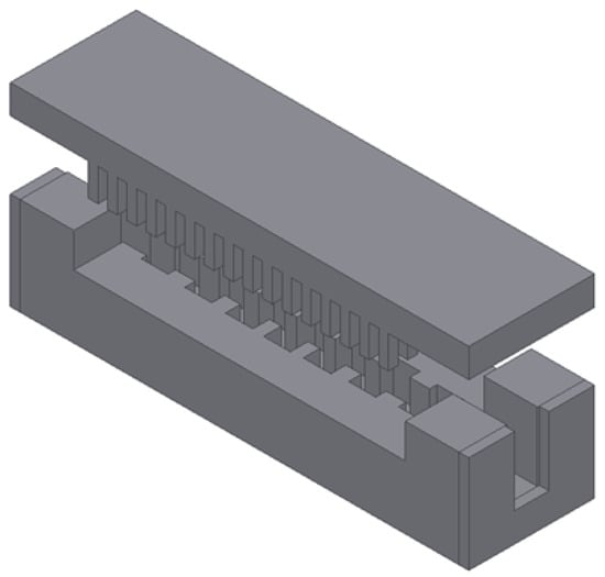
Figure 1.
Structure of a corrugated low-pass filter in HMGGW technology.
In this work, low-pass corrugated HMGGW filters operating at K- and Ka-bands are discussed. This manuscript is organized as follows. In Section 2, the HMGGW corrugated topology is presented and the filter design procedure is explained. Several corrugated low-pass filter examples in HMGGW technology are then reported in Section 3, where a comparison between the simulated and measured responses of two manufactured prototypes are also included. Finally, the main conclusions are summarized in Section 4. To the authors’ knowledge, this is the first time corrugated low-pass filters are proposed and successfully fabricated in this novel technology.
2. Theory
2.1. Half-Mode Groove Gap Waveguide (HMGGW)
The cross-section of a generic half-mode groove gap waveguide (HMGGW) is shown in Figure 2. The waveguide structure is composed of two parallel metallic pieces separated by an air gap , which is lower than to prevent radiation leaks. This new arrangement has the benefit of enabling the manufacture in two all-metal parts: the body and the lid. The lid is a bed of metallic pins with period p, yielding a high impedance surface. The bottom piece only holds the groove, with width w and height a, where a is half the equivalent waveguide width for a classical rectangular or GGW topology. The machining process is therefore simpler because there is no groove cavity or transition housed next to the metal pins. Note also how the same pin cover can be used again to implement other filters or components.
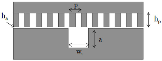
Figure 2.
Generic HMGGW cross-section.
To cover both the K- and Ka-bands, a lid with a bed of nails of period mm (square pins of 1 × 1 mm), air gap mm, and height mm has been conceived. The irreducible Brillouin dispersion diagram, obtained using the eigenmode solver of the commercial Ansys Electronics Desktop Software (HFSS, Copyright © 2023 ANSYS, Inc., Canonsburg, PA, USA. All rights reserved. [Online]. Available: https://www.ansys.com/products/electronics/ansys-hfss, accessed on 3 November 2025), is shown in Figure 3. This dispersion diagram has been obtained by applying Bloch’s theorem to the unit cell, after imposing periodic boundary conditions and then sweeping wavevectors along high-symmetry paths (e.g., for this square lattice, see Figure 3). As can be observed, the bandgap extends from 18 to 40 GHz. This large stopband can be used to implement high-bandwidth corrugated low-pass filters.
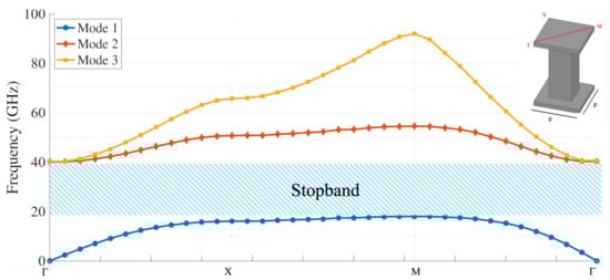
Figure 3.
Irreducible Brillouin dispersion diagram of the pin cover used for the designed filters.
2.2. Low-Pass Corrugated HMGGW Filters
For the filter design, the classical synthesis procedure for low-pass corrugated rectangular waveguide filters, developed by Levy in the 1960–1970s, can be initially used [7,23,24]. Once appropriate dimensions for the input/output waveguide have been chosen, and based on the specified passband and the required stopband performance (maximum attenuation and maximum stopband frequency or maximum attenuation frequency), this method provides the impedances and the electric length , at the passband cutoff frequency , for all the N waveguides which implement the low-pass filter (excluded input and output waveguides, so in total, there are N + 2 waveguides). These parameters are then directly transferred to the heights and commensurate length l, using the following relationships:
As soon as the height of the input waveguide is set, all the waveguide heights can be derived from (1). A commensurate structure is thus obtained, with all the waveguides of the same length l, since the distributed classical prototype is used as reference. This procedure, however, does not take into account the reactive effect produced by the higher-order modes that are excited around each waveguide discontinuity. To improve the technique, the correction proposed in [25] is applied to the waveguide lengths, taking into account that the capacitive fringing effects lead to a phase shift in the reflection coefficient of the discontinuity. Then, the offset at the i-th discontinuity of the structure is compensated by adding to each side the correction lengths given by
where is the phase of the reflection parameter of the isolated i-th discontinuity (with zero-length access ports), and is the wavelength at the passband upper cutoff frequency . As a result, the new length of the i-th waveguide is as follows:
These corrected lengths significantly improve the dimensions of the extracted structure and its electrical response. However, this correction, which is valid even for filters of very high orders, is a first order readjustment of the real structure based on a fundamental mode characterization of the steps to compensate for the effects that the classic distributed prototype is unable to account for. In fact, as proposed in [3,26], once the structure has been deduced using (1)–(4), the desired response can be recovered by performing an optimization of the lengths between discontinuities based on a multimodal full-wave model of the steps, which takes into account higher-order mode effects and the dependence with the frequency of the real elements of the structure. For the waveguide steps, a multimodal characterization using the first 30 accessible modes (and also 300 modal basis functions and 700 kernel modes), excited in a constant-width E-plane structure, has been performed. This synthesis procedure is currently integrated into the full-wave electromagnetic (EM) FEST3D software tool (FEST3D, Copyright © 2023 Dassault Systèmes. Available on: https://www.3ds.com/es/products/simulia/fest3d, accessed on 3 November 2025). It is worth pointing out that the parameters that primarily control the maximum attenuation are the type of response, the passband return loss level, and the order N of the filter.
Once the equivalent rectangular corrugated low-pass filter has been synthesized, the lengths and the heights of the waveguides (now referred to as groove widths ) obtained are used as initial values for the design of the low-pass HMGGW filter. Since the impedances and discontinuities in the HMGGW structure are not exactly the same as those in the rectangular waveguide filter, the electrical response needs a final optimization process. In this last step, the lengths and widths of the HMGGW sections are slightly tuned with Ansys HFSS full-wave electromagnetic simulator (included in Ansys Electronics Desktop Software 2023) to compensate for the different electrical length and impedance ratios with respect to rectangular waveguide technology. This process does not usually require too many iterations (around 50 optimizer iterations), although their final number mainly depends on the filter order N. Furthermore, at this stage, the interconnection with the ports must also be addressed. In case the input/output groove does not fit with a standard dimension, a transition section must also be included. For experimental verification, all the filters designed in this paper are terminated in WR28 standard rectangular ports with square flange UG-599/U of 19.05 mm.
3. Results
Several low-pass corrugated HMGGW filters in the K-band, with the groove height a set to 3.55 mm and input/output groove width mm, have been designed. All the filters detailed in this section are terminated in WR28 standard waveguide ports ( mm), using a rectangular waveguide section with length and width of mm and mm, respectively, for the transition between the HMGGW structure and the ports. Ansys HFSS has been used for the analysis and design of these filters in HMGGW technology. Waveports at input and output filter sections, as well as radiation conditions in open lateral parts, have been included.
Figure 4 shows the simulated responses ( in continuous lines and in dashed lines) of three HMGGW corrugated filters, of orders N = 11, 13, and 15, synthesized with an upper passband cutoff frequency of GHz, and different maximum attenuation levels fixed at GHz.
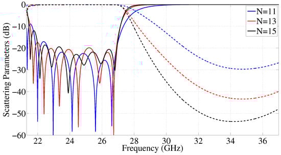
Figure 4.
Simulated responses of three corrugated HMGGW low-pass filters with cutoff frequency at 27 GHz and different orders (N = 11, 13, and 15).
The filters have been simulated assuming the material is bare aluminum, obtaining insertion losses lower than 0.14 dB in the whole passband. Return losses are better than 19.5 dB from 22.6 GHz up to 27 GHz, which corresponds to a fractional bandwidth of 16.3% (normalized with respect to ). Note how the selectivity increases with the filter order, as expected, and also the (N − 1)/2 maximum values (peaks) of the return loss in the passband. Furthermore, it is important to highlight that these structures provide a low-pass response starting from the cutoff frequency of the fundamental mode in the waveguide, thus being commonly referred to as a quasi-low-pass response.
To demonstrate the flexibility and potential of this technology, the same pin cover already defined at the end of Section 2.1 (and used for the previous examples) has been used to design a set of low-pass HMGGW filters for Ka-band operation. On the one hand, Figure 5a represents the electrical response of two corrugated filters (of orders N = 13 and N = 15), with cutoff frequency at 29.5 GHz and maximum attenuation level set at 38 GHz. On the other hand, Figure 5b plots the scattering parameters of a 15th-order low-pass filter with a cutoff frequency of 31 GHz and a maximum attenuation level at 39 GHz. For all these filters, the simulated insertion losses are less than 0.18 dB (assuming bare aluminum), and the return losses are better than 19.5 dB in a fractional bandwidth of 26.3% and 30%, respectively.
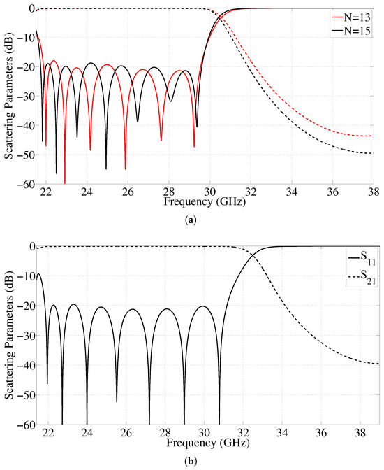
Figure 5.
Simulated responses of corrugated HMGGW low-pass filters at Ka-Band. (a) Low-pass filter with cutoff frequency at 29.5 GHz and two different orders (N = 13 and 15). (b) Low-pass filter with cutoff frequency at 31 GHz and order 15.
For experimental verification, two low-pass corrugated HMGGW filters have been manufactured and tested in the Antennas and Propagation Laboratory of Technical University of Valencia. Figure 6 shows a photograph of both prototypes, which were manufactured in-house from an aluminum alloy using a computer numerical control (CNC) Datron M25 milling machine, with tolerances of around 20 microns. The nominal dimensions of both filters are included in Table 1 and Table 2, respectively.
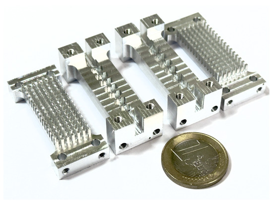
Figure 6.
Manufactured prototypes of two corrugated HMGGW low-pass filters. On the left, the lid and body of the low-pass filter with cutoff frequency at 27 GHz; on the right, those of the low-pass filter with cutoff frequency at 29.5 GHz.

Table 1.
Dimensions (in mm) of the 13-th order low-pass HMGGW filter with cutoff frequency at 27 GHz.
Table 2.
Dimensions (in mm) of the 15-th order low-pass HMGGW filter with cutoff frequency at 29.5 GHz.
The simulated and measured responses of the 13-th order low-pass HMGGW filter with cutoff frequency at 27 GHz are compared in Figure 7. An excellent agreement between both responses has been achieved, with only a minor impairment close to the cutoff frequency of the input waveguide. Measured return losses are better than 19.7 dB across the whole filter band (in fact, a 20.3% fractional bandwidth is achieved), while the insertion loss level is better than 0.25 dB inside the passband.
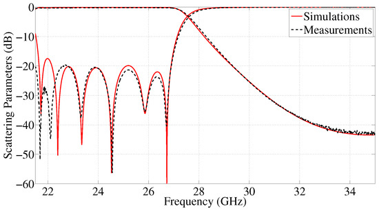
Figure 7.
Simulated and measured responses of the 13-th order low-pass HMGGW filter with cutoff frequency at 27 GHz.
Figure 8 shows the electrical response of a second manufactured filter working at the Ka-band. Again, a good agreement between simulations and measurements can be observed. The differences (close to the cut-off frequencies of the waveguide and the bandpass of the filter) can be directly attributed to the inaccuracies of the in-house manufacturing process (manufacturing tolerances around ±20 microns). In any case, measured return losses are better than 19.5 dB between 21.4 and 29.7 GHz, which corresponds to a fractional bandwidth of 28%, while insertion loss level is lower than 0.3 dB in all the filter passbands. According to the dimensions summarized in Table 1 and Table 2, the first filter prototype has an overall size of 2.08 × 0.73 × 0.73 , while the second one has 2.3 × 0.89 × 0.89 . Both manufactured devices have a weight of only 25 g. The corrugated low-pass filters designed in HMGGW technology are more than 2 mm shorter than the equivalent ones in the rectangular waveguide, leading to more compact structures. Moreover, they also inherit the benefits of the GGW technology in terms of insertion losses, as a perfect metal contact between the cover and the lid is no longer required. This is particularly relevant at high frequencies.
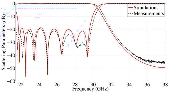
Figure 8.
Simulated and measured responses of the 15-th order low-pass HMGGW filter with cutoff frequency at 29.5 GHz.
A sensitivity analysis of the manufactured filter with cut-off frequency at 29.5 GHz has also been performed to verify the robustness of the proposed topology to fabrication tolerances. The different physical groove dimensions are randomly modified with a deviation of ±20 microns with respect to the nominal value. The results in Figure 9, which include more than three hundred iterations, clearly reveal the good resilience to manufacturing imperfections of low-pass corrugated HMGGW filters. Simulated return losses are always better than 17 dB, and the maximum shift of the upper cut-off frequency of the filter is around 400 MHz. This is a particularly relevant feature for those devices designed to operate in high frequency bands, where the variations in the physical dimensions have a greater impact on the response.
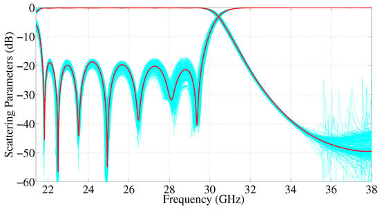
Figure 9.
Sensitivity analysis of the 15-th order low-pass HMGGW filter with cutoff frequency at 29.5 GHz.
Table 3 compares the two low-pass HMGGW filters fabricated with other low-pass filters reported in the technical literature and implemented in groove gap (GGW), ridge gap (RGW), and rectangular waveguide (RW) technologies. In this table, indicates the upper cutoff frequency. Other relevant parameters, such as filter order, insertion and return losses (IL and RL), fractional bandwidth (FBW), ratio (), and maximum out-of-band rejection level, are also shown.
Table 3.
Comparison of the performance of manufactured and referenced low-pass filters.
The manufactured HMGGW prototypes have a clear advantage in terms of losses when compared with low-pass filters implemented in ridge gap technology. The benefits are also evident over conventional low-pass corrugated filters in rectangular waveguide, as the latter has nearly the same insertion losses despite operating at half the frequency. Note that the losses increase with the frequency due to the skin effect, and especially due to the small imperfections in the metal contact between the assembled filter parts (this last degradation is fully avoided in GGW and HMGGW implementations). The GGW structure proposed in [18] has an equivalent loss performance, although it is much bulkier due to the presence of a bed of nails at both sides of the propagating waveguide and the use of a larger waveguide for the same filter order.
On the other hand, the maximum out-of-band rejection level increases with the filter order (see Figure 4) and with a reduction in the fractional bandwidth. As a result, the performance of the HMGGW topology surpasses the one of the GGW implementation, although it can be slightly worse than for ridge waveguide (RGW) and rectangular waveguide (RW) low-pass filters. With respect to the power handling capability of HMGGW filters, the air gap between the cover and the lid can limit the input power threshold due to multipactor (under high-vacuum conditions) or corona. Previous studies in GGW technology reveal that multipactor can be avoided in the bed of nails by using a gap of a few microns (to keep the frequency-gap product below mm × GHz) [29,30], although this would cause larger EM fields that can foster a corona discharge at higher pressures [31]. This relevant issue will be studied and verified in future work for HMGGW technology.
From the previous comparative analysis, the low-pass HMGGW implementation is the best approach for low-pass filters operating at high frequency bands with demanding insertion loss requirements, resulting in a much more compact solution than its GGW counterpart. Furthermore, the excellent agreement between the measured and simulated electrical responses, in spite of the in-house milling process with moderate tolerances, reveals the outstanding manufacturability properties of the proposed low-pass filter topology.
4. Conclusions
In this paper, for the first time, low-pass corrugated filters in half-mode groove gap waveguide (HMGGW) technology have been designed and manufactured. The design starts from the synthesis strategy used for corrugated low-pass filters in standard rectangular waveguide and only requires an additional final refinement of the widths and lengths of the grooved waveguides to achieve the desired electrical response.
In contrast to GGW, the alternation between low and high impedance levels required by a corrugated low-pass filter can be easily implemented by just modifying the width of consecutive groove sections. This leads to a simple and easy to manufacture implementation, which inherits the compactness and low insertion loss of corrugated low-pass filters. Furthermore, it also benefits from the absence of losses in the mating between the filter body and cover. As a result, a high-performance low-pass filter implementation is obtained for operation at high frequency ranges.
Within the bandstop frequency region of the bed of pins integrated in the cover, any low-pass HMGGW filter response can be synthesized regardless of its cut-off frequency, return loss, and out-band performance. The excellent agreement between simulated and measured data of two prototypes, manufactured with a computer numerical control (CNC) machine, fully validates the use of the HMGGW technology for implementing low-pass corrugated filters at K- and Ka-bands.
Author Contributions
Conceptualization, S.M., P.S. and V.E.B.; methodology, S.M., P.S. and V.E.B.; software and data curation, A.S.R. and E.G.N.; validation, P.S. and V.E.B.; writing—original draft preparation S.M. and A.S.R.; writing—review and editing, P.S. and V.E.B.; supervision, S.M. and V.E.B.; funding acquisition, S.M. and V.E.B. All authors have read and agreed to the published version of the manuscript.
Funding
This work was funded by MCIN/AEI/10.13039/501100011033 and by “FEDER, a way of making Europe,” through Subprojects C43, and C41 of the Coordinated Projects PID2022-136590OB.
Data Availability Statement
The original contributions presented in this work are included in the article. Further inquiries can be directed to the corresponding author.
Acknowledgments
The authors would like to thank the Antennas and Propagation Lab (APL–iTEAM UPV) for fabrication of the prototypes.
Conflicts of Interest
The authors declare no conflicts of interest. The funders had no role in the design of the study; in the collection, analyses, or interpretation of data; in the writing of the manuscript; or in the decision to publish the results.
Abbreviations
The following abbreviations are used in this manuscript:
| HMGGW | Half-Mode Groove Gap Waveguide |
| RF | Radio frequency |
| CRLH-TL | Composite Right/Left Handed Transmission Lines |
| H-CSSRR | Hilbert-shaped Complementary Single Split Ring Resonator |
| GGW | Groove Gap Waveguide |
| CNC | Computer Numerical Control |
| RW | Rectangular Waveguide |
| RGW | Ridge Gap Waveguide |
| IL | Insertion Losses |
| RL | Return Losses |
| FBW | Fractional Bandwidth |
References
- Cameron, R.J.; Kudsia, C.M.; Mansour, R. Microwave Filters for Communication Systems: Fundamentals, Design, and Applications; John Wiley & Sons: Hoboken, NJ, USA, 2018. [Google Scholar]
- Uher, J.; Bornemann, J.; Rosemberg, U. Waveguide Components for Antenna Feed Systems: Theory and CAD; Artech House: Norwood, MA, USA, 1993. [Google Scholar]
- Boria, V.E.; Soto, P.; Cogollos, S. Distributed models for filter synthesis. IEEE Microw. Mag. 2011, 12, 87–100. [Google Scholar] [CrossRef]
- Arregui, I.; Teberio, F.; Arnedo, I.; Percaz, J.M.; Martin-Iglesias, P.; Lopetegi, T.; Laso, M.A. High-power filter design in waveguide technology. IEEE Microw. Mag. 2020, 21, 46–57. [Google Scholar] [CrossRef]
- Matthaei, G.L.; Young, L.; Jones, E.M. Microwave Filters, Impedance-Matching Networks, and Coupling Structures; Artech House: Norwood, MA, USA, 1980. [Google Scholar]
- Levy, R.; Rozzi, T. Precise design of coaxial low-pass filters. IEEE Trans. Microw. Theory Tech. 1968, 16, 142–147. [Google Scholar] [CrossRef]
- Levy, R. Tapered corrugated waveguide low-pass filters. IEEE Trans. Microw. Theory Tech. 1973, 21, 526–532. [Google Scholar] [CrossRef]
- Kumar, A.; Upadhyay, D.K. CRLH-TL based compact planar dual band lowpass-wide bandpass filter. In Proceedings of the 2024 International Conference on Signal Processing and Advance Research in Computing (SPARC), Lucknow, India, 12–13 September 2024; pp. 1–5. [Google Scholar]
- Ayaz, M.; Iftikhar, A.; Braaten, B.; Khalil, W.; Ullah, I. A composite right/left-handed phase shifter-based cylindrical phased array with reinforced particles responsive to magneto-static fields. Electronics 2023, 12, 306. [Google Scholar] [CrossRef]
- Xu, H.X.; Wang, G.M.; Zhang, C.X.; Peng, Q. Hilbert-shaped complementary single split ring resonator and low-pass filter with ultra-wide stopband, excellent selectivity and low insertion-loss. AEÜ-Int. J. Electron. Commun. 2011, 65, 901–905. [Google Scholar] [CrossRef]
- Xu, H.X.; Wang, G.M.; Zhang, C.X. Fractal-shaped UWB bandpass filter based on composite right/left-handed transmission line. Electron. Lett. 2010, 46, 285–287. [Google Scholar] [CrossRef]
- Kildal, P.-S.; Alfonso, E.; Valero-Nogueira, A.; Rajo-Iglesias, E. Local metamaterial-based waveguides in gaps between parallel metal plates. IEEE Antennas Wirel. Propag. Lett. 2008, 8, 84–87. [Google Scholar] [CrossRef]
- Rajo-Iglesias, E.; Ferrando-Rocher, M.; Zaman, A.U. Gap waveguide technology for millimeter-wave antenna systems. IEEE Commun. Mag. 2018, 56, 14–20. [Google Scholar] [CrossRef]
- Shen, Y.; Zhang, T.; Luo, L.; Zhu, H.; Chen, L. 4 × 4 Wideband slot antenna array fed by TE440 mode based on groove gap waveguide. Electronics 2025, 14, 813. [Google Scholar] [CrossRef]
- Berenguer, A.; Fusco, V.; Zelenchuk, D.E.; Sánchez-Escuderos, D.; Baquero-Escudero, M.; Boria, V.E. Propagation characteristics of groove gap waveguide below and above cutoff. IEEE Trans. Microw. Theory Tech. 2016, 64, 27–36. [Google Scholar] [CrossRef]
- Maximo-Gutierrez, C.; Hinojosa, J.; Alvarez-Melcon, A. Design of evanescent mode band-pass filters based on groove gap waveguide technology. AEÜ-Int. J. Electron. Commun. 2023, 164, 154628. [Google Scholar] [CrossRef]
- Liu, Z.; Cheng, X.; Yao, Y.; Yu, T.; Yu, J.; Chen, X. Broadband transition from rectangular waveguide to groove gap waveguide for mm-wave contactless connections. Electronics 2020, 9, 1820. [Google Scholar] [CrossRef]
- Santiago, D.; Laso, M.A.; Lopetegi, T.; Arregui, I. Novel design method for millimeter-wave gap waveguide low-pass filters using advanced manufacturing techniques. IEEE Access 2023, 11, 89711–89719. [Google Scholar] [CrossRef]
- Gadelrab, M.; Shams, S.I.; Elsaadany, M.; Sebak, A. Ridge gap waveguide low pass filters: A systematic design approach. IEEE Access 2024, 12, 81992–82001. [Google Scholar] [CrossRef]
- Ferrando-Rocher, M.; Herranz-Herruzo, J.I.; Valero-Nogueira, A.; Baquero-Escudero, M. Half-mode waveguide based on gap waveguide technology for rapid prototyping. IEEE Microw. Wirel. Compon. Lett. 2021, 32, 117–120. [Google Scholar] [CrossRef]
- Marini, S.; Ferrando-Rocher, M.; Morales-Hernández, A.; Gimeno, E.; Jorge López, A.; Boria, V.E. Ka-band diplexer design based on half-mode groove gap waveguide. AEÜ-Int. J. Electron. Commun. 2024, 175, 155062. [Google Scholar] [CrossRef]
- Ferrando-Rocher, M.; Herranz-Herruzo, J.I.; Valero-Nogueira, A.; Baquero-Escudero, M. Half-mode groove gap waveguide for single-layer antennas in the millimeter-wave band. IEEE Antennas Wirel. Propag. Lett. 2022, 21, 2402–2406. [Google Scholar] [CrossRef]
- Levy, R. Tables of element values for the distribuited low-pass prototype filter. IEEE Trans. Microw. Theory Tech. 1965, 13, 519–535. [Google Scholar] [CrossRef]
- Levy, R. A generalized design technique for practical distribuited reciprocal ladder networks. IEEE Trans. Microw. Theory Tech. 1973, 21, 518–526. [Google Scholar] [CrossRef]
- Simeoni, M.; Cacchione, S.; Vanin, F.; Molina-Pérez, J.; Schmitt, D. Automatic dimensional synthesis without optimization for stepped impedance low-pass filters. Microw. Opt. Technol. Lett. 2005, 44, 190–194. [Google Scholar] [CrossRef]
- Monneris, O.; Soto, P.; Cogollos, S.; Boria, V.E.; Gil, J.; Vicente, C.; Gimeno, B. Accurate circuit synthesis of low-pass corrugated waveguide filters. In Proceedings of the 40th European Microwave Conference, Paris, France, 28–30 September 2010; pp. 1237–1240. [Google Scholar]
- Teberio, F.; Gomez-Torrent, A.; Arregui, I.; Percaz, J.M.; Arnedo, I.; Chudzik, M.; Lopetegi, T.; Laso, M.A. Sensitivity analysis of a 3-D printed low-cost compact waveguide low-pass filter. In Proceedings of the 46th European Microwave Conference, London, UK, 4–6 October 2016; pp. 249–252. [Google Scholar]
- Vera, P.; Correas, D.; Quesada, F.; Hinojosa, J.; Álvarez, A. A novel low-pass filter based on rounded posts designed by an alternative full-wave analysis technique. IEEE Trans. Microw. Theory Tech. 2014, 62, 2300–2307. [Google Scholar]
- Vague, J.J.; Asensio, I.; Coves, Á.; San- Blas, Á.A.; Reglero, M.; Vidal-Pantaleoni, A. Study of the multipactor effect in groove gap waveguide technology. IEEE Trans. Microw. Theory Tech. 2022, 70, 2566–2578. [Google Scholar] [CrossRef]
- Jorge-López, A.; Vague, J.J.; Asensio, I.; Coves, Á.; San-Blas, A.A.; Baquero-Escudero, M. Theoretical and experimental results for multipactor effect in groove gap waveguide bandpass filters with inductive coupling irises. IEEE Access 2024, 12, 187844–187856. [Google Scholar] [CrossRef]
- Morales-Hernández, A.; Sánchez-Soriano, M.A.; Ferrando-Rocher, M.; Marini, S.; Boria, V.E. In-depth study of the corona discharge breakdown thresholds in groove gap waveguides and enhancement strategies for inductive bandpass filters. IEEE Access 2022, 12, 129149–129162. [Google Scholar] [CrossRef]
Disclaimer/Publisher’s Note: The statements, opinions and data contained in all publications are solely those of the individual author(s) and contributor(s) and not of MDPI and/or the editor(s). MDPI and/or the editor(s) disclaim responsibility for any injury to people or property resulting from any ideas, methods, instructions or products referred to in the content. |
© 2026 by the authors. Licensee MDPI, Basel, Switzerland. This article is an open access article distributed under the terms and conditions of the Creative Commons Attribution (CC BY) license.