Abstract
Mobile edge computing (MEC) has emerged as a promising paradigm to enhance computational capabilities at the network edge, enabling low-latency services for users while ensuring efficient resource utilization for operators. One of the key challenges in MEC is optimizing offloading decisions and resource allocation to balance user experience and operator profitability. In this paper, we integrate software-defined networking (SDN) and MEC to enhance system utility and propose an SDN-based MEC network framework. Within this framework, we formulate an optimization problem that jointly maximizes the utility of both users and operators by optimizing the offloading decisions, communication and computation resource allocation ratios. To address this challenge, we model the problem as a Markov decision process (MDP) and propose a reinforcement learning (RL)-based algorithm to optimize long-term system utility in a dynamic network environment. However, since RL-based algorithms struggle with large state spaces, we extend the MDP formulation to a continuous state space and develop a deep reinforcement learning (DRL)-based algorithm to improve performance. The DRL approach leverages neural networks to approximate optimal policies, enabling more effective decision-making in complex environments. Experimental results validate the effectiveness of our proposed methods. While the RL-based algorithm enhances the long-term average utility of both users and operators, the DRL-based algorithm further improves performance, increasing operator and user efficiency by approximately 22.4% and 12.2%, respectively. These results highlight the potential of intelligent learning-based approaches for optimizing MEC networks and provide valuable insights into designing adaptive and efficient MEC architectures.
1. Introduction
With the rapid development of vehicular communication, augmented reality, mobile gaming, and internet of things (IoT) applications, traditional cloud computing service can no longer meet the increasingly stringent requirements for computing service. The market urgently demands a new computing paradigm to address users’ needs for low latency, flexibility, virtualization, and context awareness in computing service. Mobile edge computing (MEC) has emerged as a promising solution [1,2,3]. Unlike traditional cloud computing, which centralizes computing, storage, and network management in large-scale data centers, mobile edge computing (MEC) brings IT services and cloud capabilities closer to end users. By operating at the edge of mobile networks—within wireless access networks and near mobile devices—MEC reduces latency, enhances network efficiency, and improves service delivery, ultimately providing a better user experience. Additionally, the MEC framework supports the deployment of applications and services across multi-vendor platforms, enabling seamless access for users across different mobile operators and enhancing the commercial value for operators.
In the process of providing MEC service to users, a key research challenge is how operators can ensure the quality of service (QoS) for users while safeguarding their own interests. Generally, QoS can be evaluated using various metrics, with two of the most commonly considered being the delay for the completion of computational tasks [4,5,6] and the energy consumed to complete these tasks [7,8,9,10]. On one hand, traditional cloud computing often struggles to meet low-latency requirements due to factors such as the geographical remoteness of cloud data centers and data congestion in backbone networks. In contrast, MEC enables task processing at the network’s “edge”, significantly reducing the time spent during data transmission and better satisfying users’ low-latency demands. On the other hand, most mobile devices have limited battery capacity with infrequent opportunities for timely recharging, making energy consumption optimization in MEC another prominent area of research. Recent studies have focused on jointly optimizing latency and energy consumption, treating them as critical aspects of MEC. For instance, researchers often assign weights to latency and energy consumption, combining them into a single metric (commonly referred to as “cost”) to be optimized as a measure of QoS [11,12,13]. In addition to latency and energy consumption, other factors affecting QoS include the size of computational tasks, the probability of task processing failures, and the rate of task processing. Recent studies have incorporated these factors alongside latency and energy consumption to design comprehensive utility functions aimed at enhancing user experience [14,15,16,17,18]. However, these utility functions are predominantly user-oriented. For operators, to safeguard their own interests, it is necessary to design a utility function aligned with their objectives during the provision of MEC services to users, ensuring it remains at an acceptable level.
How to optimize from both user and operator perspectives under a dynamic environment for MEC remains an issue. Recent studies in the field of MEC have proposed several promising directions for optimizing the utility of both users and operators. Key research focuses include task offloading for mobile devices, communication resource allocation at edge nodes, and computational resource allocation at edge servers. Although MEC can provide users with enhanced computational capabilities, the simultaneous offloading of tasks by multiple users to the edge server may overwhelm its computational resources, degrading the user experience. To address this, it is essential to design efficient task offloading schemes that determine where the computational tasks of mobile devices should be processed. One of the most advanced approaches is to use game theory [16,19,20] and deep reinforcement learning [9,10,13,14,21,22,23] to develop online learning algorithms. These algorithms enable network devices to learn and optimize offloading strategies dynamically during operation. In a multi-user MEC system, different access schemes lead to varying communication resource allocation challenges. For example, if OFDMA access technology is used, the channel between edge nodes and users needs to be divided into multiple subchannels with appropriate bandwidths to meet the access requirements of multiple users [24]. If TDMA access technology is used, the TDMA frames between edge nodes and users need to be divided into time slots of varying lengths, allowing multiple users to transmit data in different time periods [25]. A more complex approach involves combining two access technologies. For example, NOMA and TDMA are integrated by grouping multiple users. Within each group, users access the channel using NOMA, while TDMA is employed between groups to share channel resources [26,27]. Similarly, when multiple users offload computational tasks simultaneously to an edge server, the server must allocate its computational resources efficiently to each user to enhance overall network performance. Effective resource allocation schemes in such scenarios are critical for optimizing network utility and ensuring the quality of service for all users [28].
How to deploy MEC infrastructure? The European Telecommunications Standards Institute (ETSI) and recent researchers have proposed an effective solution for deploying MEC infrastructure: MEC is implemented on a virtualization platform that leverages the latest advancements in network function virtualization (NFV) and SDN [29,30]. SDN is an innovative network technology that separates the control logic of the network from the underlying routers, creating an independent control layer. This significantly simplifies the data plane, facilitating easier control programming for administrators [29]. Typically, the structure of SDN is divided into three layers: the application layer, the control layer, and the infrastructure layer [31]. The control layer is responsible for collecting state information from network devices in the infrastructure layer, forming control information that ensures efficient operation of infrastructure devices. Administrators manage the entire network through programming interfaces in the application layer. NFV is another critical technology. Its primary role is to create multiple virtual machines (VMs) that virtualize various network functions of proprietary hardware devices, allowing a single network device to provide multiple information services to various mobile devices [32,33].
In this paper, we investigate the resource allocation and task scheduling problems in multi-user scenarios within MEC, focusing on task offloading decisions, communication bandwidth, and computational resource allocation. First, we propose an MEC network framework that adheres to MEC standards, based on an SDN design and integrating NFV technology. Based on this network framework, we design utility functions from both the user and operator perspectives. To maximize the long-term average utility of both users and operators, we reformulate the problem as an MDP and develop an RL-based learning algorithm. Given the suboptimal performance of RL-based algorithms in more complex network environments, we further propose a DRL-based learning algorithm to improve overall network performance. Subsequent experimental results demonstrate that the RL-based learning algorithm can effectively optimize the long-term average utility of both users and operators in dynamic network environments, while the DRL-based learning algorithm improves operator and user utility by 22.4% and 12.2%, respectively, compared to the RL-based approach. In summary, the main contributions of our work are as follows:
- (1)
- We designed an SDN-based MEC network framework that integrates NFV technology. By utilizing the virtualized functions of NFV, the functionalities of various hardware devices are centralized in the NFV Infrastructure Nodes (NFVI Node), simplifying the network’s hardware components.
- (2)
- Based on the proposed network framework, we designed utility functions from both the user and operator perspectives. We then employed RL and DRL-based algorithms to optimize the long-term average utility of users and operators in dynamic network environments.
- (3)
- Using the proposed MEC framework and RL/DRL-based algorithms, we designed corresponding experiments. The experimental results show that the RL and DRL-based algorithms we proposed effectively improve the long-term average utility of both users and operators in dynamic network environments.
The remainder of this paper is organized as follows: In Section 2, we present the system model, which includes the SDN-based MEC network framework, communication model, latency and energy consumption models, etc. In Section 3, we define the optimization objectives from both the user and operator perspectives, i.e., their respective utility functions. In Section 4, we provide detailed processes for the RL-based and DRL-based learning algorithms. The experimental results are presented in Section 5. Section 5 discusses limitations and future work. Finally, Section 6 concludes the paper.
2. System Model
2.1. SDN-Based MEC Network Framework
Figure 1 illustrates the SDN-based MEC network framework, which is divided into three layers: the application layer, the control layer, and the infrastructure layer.
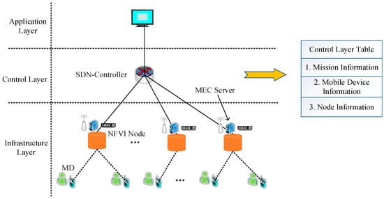
Figure 1.
SDN-based MEC Network Framework.
The application layer is mainly composed of management terminals, which control the lower-layer devices through the northbound programming interfaces provided by the control layer. The control authority of the network is handed over to the MEC operator, who designs network operation rules based on the network environment and develops various services and applications for MDs.
The control layer is mainly composed of the SDN-Controller, which provides interfaces for network control to the application layer devices and manages resource scheduling of the lower-layer devices. The control layer is derived from separating the control plane of network switches or routers from the data plane. The SDN-Controller controls the network primarily through the southbound interface protocol OpenFlow [34]. The protocol rules include link discovery, topology management, table management, and policy formulation. Link discovery, topology management, and table management are mainly monitored, and statistics are gathered through the uplink channel of the interface, which reports information from the underlying switching devices. Policy formulation is achieved by using the downlink channel of the interface to uniformly control the network devices.
The infrastructure layer is composed of the NFVI Node and mobile devices (MDs). The NFVI Node provides an NFV platform that can virtualize the functions of wireless access points and MEC servers for MDs, offering data access and MEC services. It can also virtualize the switch functions for the upper-layer SDN-Controller, providing data forwarding services.
In the SDN-based MEC network, each MD periodically generates its own computational tasks, and these tasks follow a binary offloading strategy [22], meaning that all task data are either offloaded to a virtual MEC Server for processing or remain to be processed on the MD’s computational unit. The SDN-Controller maintains a task information table based on the MD task data reported by the lower-layer devices. This table includes task data size, required computational resources for task completion, and other relevant details. The SDN-Controller controls the completion of edge computing tasks by the MDs based on the network state and the status of the MDs. To do so, it maintains an MD information table, which consists of the computational resources of each MD. Additionally, the SDN-Controller must establish and maintain a node information table for all NFVI Nodes, which includes the channel states between virtual wireless access points and MDs, as well as the computational resources of virtual MEC Servers.
Based on the described edge computing network framework, the task processing flow for MDs can be defined as follows: The MD periodically sends its task and computational resource information to the NFVI Node. The NFVI Node forwards the MD information and its own node information to the SDN-Controller via a virtual switch. Upon receiving this information, the SDN-Controller updates all the information tables. Then, based on the data in these tables, the SDN-Controller formulates the task offloading and resource allocation strategies and generates control information, which is then delivered to the network devices in the infrastructure layer for execution.
2.2. System Model
In the system, let the set represent the NFVI Nodes, and the virtual MEC Servers configured within each NFVI Node provide users with strong edge computing capabilities. Let the set represent the MDs served by each NFVI Node, where the MDs can represent various types of IoT devices, such as smartwatches, smartphones, and wearable devices. To reduce the latency impact caused by control information forwarding, the NFVI Node is associated with the SDN-Controller via wired optical fiber links. The management terminal collects information from the SDN-Controller to manage the entire edge computing network.
Each MD periodically generates compute-intensive and delay-sensitive tasks, which can either be processed by the MD’s own computational unit or offloaded to the virtual MEC Server in the NFVI Node for processing. During the operation of the entire network, time is divided into time slots with a constant duration. The length of each time slot is denoted by , and the index of the time slot is represented by , . In time slot , MD generates computation task , where represents the computational resources required to complete task , i.e., the number of CPU cycles needed to complete the task. represents the size of the data associated with this task. Let denote the computational capability of MD and represent the computational capability of the MEC Server in NFVI Node . In the system, each NFVI Node can serve multiple MDs simultaneously, and each MD can only be associated with one NFVI Node.
2.3. Communication Model
We assume a Rayleigh fading channel model. Let denote the channel power gain between MD and NFVI Node , which remains constant within a single time slot and is an independent and identically distributed (i.i.d.) inter slot. Let represent the transmission power of MD and denote the noise power. According to [35], the spectral efficiency between MD and NFVI Node can be expressed as
where represents the distance between MD and NFVI Node , and denotes the path loss exponent characterizing signal attenuation during propagation.
In time slot , each MD has two options for processing its computation tasks, either process the task locally on its own computation unit or offload it to the NFVI Node for processing. Thus, each MD has two choices, denoted as , where indicates the task is processed locally on the MD’s computation unit, and indicates the task is offloaded to the virtual MEC Server on NFVI Node . At the initial state, each MD associates with a specific NFVI Node to obtain data and MEC services. When an MD chooses to offload its computation task to the NFVI Node, a transmission delay occurs, which can be expressed as follows:
where represents the data transmission rate between MD and NFVI Node , represents the total bandwidth resources of NFVI Node , represents the proportion of bandwidth resources allocated by NFVI Node to MD in time slot , and .
2.4. Delay and Energy Consumption Model
The delay model: When a computational task is processed in the MD’s own computing unit, the processing delay depends on the required computational resources and the computational capability of the MD . Thus, in time slot , the processing delay for the task on the MD can be expressed as
When the computation task is offloaded to the virtual MEC Server on an NFVI Node, the processing delay depends on the computational resources required by the task and the computational resources allocated to the virtual MEC Server. Therefore, in time slot , if the computation task of MD is offloaded to NFVI Node , its processing delay can be expressed as
In the formula, represents the ratio of the computational resources allocated to MD to the total computational resources of the virtual MEC Server in NFVI Node , and .
Based on the analysis of the communication model and the computation model, the total delay generated by MD processing the computation task in time slot can be expressed as
In the above process, since the computation results of the task and the control information in the network are relatively small, the delay caused by returning the computation results from the virtual MEC Server to MD and the delay from forwarding control information in the network are ignored [2,17].
Energy consumption model: The energy consumption of MD can be calculated as follows: If, in time slot , MD processes the computation task in its own computing unit, it will generate a local computational energy consumption. The consumed energy can be expressed as [8]
where represents the energy consumed per unit CPU cycle. If, in time slot , MD offloads its computation task to the NFVI Node for processing, it will generate a communication energy consumption during the data transmission. The consumed energy can be expressed as
Therefore, in time slot , the energy consumption of MD can be expressed as
3. Problem Formulation
Based on the aforementioned SDN-based MEC model, the entire system workflow can be defined as follows: In the initial state , all MDs are associated with the NFVI Node within their signal range, and the SDN-Controller begins to collect information from the entire network. At the beginning of the time slot , the MD generates computation-intensive and delay-sensitive tasks and sends its task information to the associated NFVI Node. The NFVI Node forwards the MD’s task information , its own node information, and channel state information to the SDN-Controller via the virtual switch. The SDN-Controller updates its control plane entries and, based on these entries, makes offloading decisions and resource allocation schemes for each MD in the system associated with the NFVI Node. The control information is then delivered to the NFVI Node and MD in the infrastructure layer for execution. If the computation task is processed by the NFVI Node, the result is sent back to the corresponding MD via the virtual wireless access point after processing. During the task processing, if the total processing time of the chosen method exceeds the length of a time slot, it indicates that the task processing has failed.
3.1. Maximizing the Operator’s Long-Term Average Utility
In the process above, if a user offloads their computation task to an NFVI Node for edge computing, the edge computing operator will charge the user for the computation task. At the same time, since the operator rents communication and computation resources from upstream network service providers, they need to pay the internet service providers. Therefore, the revenue calculation for the operator in a time slot can be expressed as follows:
Communication revenue: The operator’s communication revenue can be defined as the communication fee charged to the user minus the cost paid to the upstream network service provider, as follows:
where represents the price per unit of data transmitted by the MD , and represents the price per unit of communication resource leased from the Internet service provider.
The computation revenue for the edge computing operator can be defined as the computation fee charged to the user minus the cost paid to the upper-level network service provider, as follows:
where represents the unit price of the computing resources required to complete the computation task, and represents the price at which the operator purchases computing resources from the upper-level network service provider.
Therefore, the revenue of the operator when the MD processes the computation task on the MEC server in a time slot , i.e., the utility function, can be represented as
Thus, the total utility of all NFVI Node systems in the edge computing network is represented as
From the perspective of the operator, we aim to maximize the long-term average revenue of the entire network. Therefore, the problem can be formulated as the following constrained optimization problem:
where constraint C1 represents the offloading decision variable. When , it indicates that the MD processes the computational tasks within its own computing unit. When , it indicates that the MD chooses to offload the computational tasks to the NFVI Node for processing. Constraint C2 represents the communication resource allocation variable, where the sum of the communication resources allocated to all MDs associated with each NFVI Node should not exceed the total communication resources available at that NFVI Node. Constraint C3 represents the computing resource allocation variable, where the sum of the computing resources allocated to all MDs associated with each NFVI Node should not exceed the total computing resources available at the virtual MEC Server within that NFVI Node. Constraint C4 indicates that the task processing delay for each MD should not exceed the duration of a single time slot. Constraint C5 stipulates that the number of MDs accessing each NFVI Node should not exceed Ω.
3.2. Maximize the Long-Term Average Utility of Users
In the process of providing edge computing services, edge computing operators need to consider user experience. From the perspective of all users in the network, the larger the data volume of MD computing tasks, the better. The energy consumption and delay of MD should be as small as possible. Therefore, the utility function of all users in the network can be defined as
In the formula, x, y, and z represent the weight coefficients of MD data volume, energy consumption, and delay, respectively. From the user’s perspective, we aim to maximize the long-term average utility of MD under the constraints. Therefore, the problem can be formulated as the following constrained optimization problem:
Since in problem P2 the completion time of the computing task is considered as an optimizable dependent variable, we have eliminated the maximum completion time constraint for the computing task. Instead, we aim to minimize the processing time of the computing task in the optimization objective. The other constraints remain the same as in P1.
4. The Proposed Method
Under different network conditions, the utility of operators and users will keep changing. To maximize the long-term average efficiency of both, we first transform problems P1 and P2 into MDPs and then use RL-based learning algorithms to solve problems P1 and P2. Since RL-based learning algorithms suffer from performance degradation when the network environment is complex, it is difficult to deal with the situation where there are many network environment states and many MD selection actions. Subsequently, we will use DRL-based learning algorithms to expand the network’s discrete state space into a continuous state space to further solve this problem.
4.1. Reinforcement Learning (RL)-Based Learning Algorithm
MDP is a theoretical framework that achieves goals through interactive learning. The object that performs learning and implements decision-making (in this paper, the SDN-Controller) is called the agent. Everything outside the agent that interacts with it (in this paper, MD and NFVI Node) is called the environment. The two continuously interact, the agent selects actions, and the environment responds to these actions and presents new states to the agent. The environment also generates a reward (corresponding to the utility of the operator or user), which is the goal that the agent wants to optimize in the action selection process [36].
In each discrete time slot , the agent and the environment interact. In each time slot , the state of the environment observed by the agent is denoted by , and, based on this, the agent selects an action . In the next time slot, as a result of its action, the agent receives a numerical reward and transitions to the next state . Thus, the environment and the agent together produce a sequence or trajectory . From this trajectory, we can see that the reward differs from the optimization objectives in our problems P1 and P2, so we need to segment such trajectories into episodes. We first define a terminal state T, and whenever the MDP trajectory reaches this state, it indicates the end of the current trajectory, i.e., the end of an episode. Based on this definition, we can formulate the optimization objective as maximizing the long-term average reward, i.e., . At this point, the optimization objective of the algorithm is essentially consistent with the objective functions in problems P1 and P2, and the condition is implicitly contained in each episode during the algorithm optimization process. Since the RL-based learning algorithm belongs to a model-free RL problem, the state transition probabilities are not involved. Therefore, the MDP can be represented as a triplet , where represents the state space, represents the action space, and represents the reward function. Next, we correspond each component of the MDP with the model in the SDN-based MEC network one by one.
State: For MD , the parameter that can change its network state is the square of the channel gain amplitude, i.e., . We divide the square of the channel gain amplitude into equal-probability spaces. Each interval has two upper and lower thresholds, denoted as , where , and satisfies
where denotes the probability density function (PDF) of in the presence of Rayleigh fading, which is given by . For any , we say is in state . Since it is a continuous variable, we let equal the quantized value in state . The expression for is given as follows:
In this way, the state space of MD can be represented as . The state space of an NFVI Node system can be represented as . Therefore, in time slot , the state of an NFVI Node system can be represented as
Action: For MD , its action is composed of the offloading decision variable , the communication resource allocation ratio , and the computation resource allocation ratio , i.e., . For an NFVI Node system, the action space that the SDWN-Controller selects for MD can be represented as . Therefore, the action of the SDWN-Controller agent in time slot can be represented as
Reward: In reinforcement learning, when the agent selects an action in state , it receives a reward and transitions to the next state , denoted as . Here, is a one-step reward. From the operator’s perspective, the reward is the sum of the efficiencies of all MDs in an NFVI Node system. Therefore, the reward obtained by the SDWN-Controller agent when selecting an action in state can be defined as
where is the operator’s utility produced by MD i, determined by Equation (11). Here, we define the operator’s utility as 0 when the MD processes the computing task on its own computing unit. When the MD offloads the computing task to the edge server, if the edge server fails to complete the computing task within the length of a time slot, the operator’s utility is . Finally, our optimization objective is to maximize the operator’s long-term average utility, i.e., P1. From the user’s perspective, the reward is the sum of the efficiencies of all MDs in an NFVI Node system. Therefore, when solving problem P2, the reward obtained by the SDWN-Controller agent when selecting an action in state can be defined as
At this point, our optimization objective becomes maximizing the user’s long-term average utility, i.e., P2.
After defining states, actions, and rewards, how do we measure the value of selecting a particular action in a given state in the algorithm? RL-based learning algorithms typically use a value function to measure the value of state-action pairs, i.e., the value of taking action in state is denoted as . The higher the action value corresponding to the current state, the higher the reward that will be obtained by choosing and executing this action. Generally, in the initial state, the value of all state-action pairs is set to 0, and during the algorithm’s training process, it is updated using
to update the value of each state-action pair. In Formula (19), represents the learning rate, and represents the discount factor. Meanwhile, the algorithm establishes a Q-table to store the values of all state-action pairs and saves this Q-table in memory. We hope that under the condition of time-varying network states, in each time slot , we can find an optimal policy in the Q-table to maximize our objective function, and this optimal policy should satisfy , i.e., in each state, the action that maximizes its value can be chosen. The result is that our algorithm can find the action that maximizes the efficiency of users or operators in each state after sufficient training. Algorithm 1 provides the training process of the RL-based learning algorithm.
| Algorithm 1: Long-Term Average Utility Maximization Based on RL (Training Phase) |
|
In the RL-based learning algorithm, there are two different strategies, namely the behavior policy and the target policy. The behavior policy is mainly used for the algorithm to explore the state space and action space to establish the Q-table. Generally, the -greedy () method is used to balance its exploration and exploitation capabilities, so that the algorithm can converge, i.e., after observing state each time, it randomly selects an action in the state space with a probability of and selects the action that maximizes the current state value from the Q-table with a probability of . This part of the content corresponds to steps 4–6 of the RL-based training algorithm. After selecting action in state , the reward is calculated based on the system model of the SDN-based MEC network, and the next state is entered, and the value of the current state-action pair in the Q-table is updated according to Formula (19) using the obtained reward. This part of the content corresponds to steps 7–9 of the training algorithm. In each episode, the rewards of all time slots are accumulated and finally divided by the length of the episode to obtain the long-term average utility, i.e., steps 10–12. According to the training stage of the RL-based learning algorithm, we can obtain a well-trained Q-table, which includes the true values of all state-action pairs. Next, in the actual operation stage of the algorithm, the target policy will find the optimal policy according to the well-trained Q-table and obtain the best long-term average utility when the algorithm is actually running, which is usually higher than the value converged during the algorithm training process.
The training stage of the RL-based reinforcement learning algorithm is mainly to find the optimal value of each state-action pair and store it in the Q-table. According to [37], we know that can definitely converge to after a sufficiently long training time. In the actual operation stage of the algorithm, the target policy finds actions according to the greedy strategy , so the utility obtained by the algorithm is definitely the best utility that can be obtained in the current state.
4.2. DRL-Based Learning Algorithm
RL-based learning algorithms can use a Q-table to store the value of each state-action pair when the state space and action space are discrete and of low dimension. However, when the state space is continuous, it is clearly impossible to store the values of all state-action pairs in memory using a Q-table due to the limited memory of devices. Moreover, RL-based learning algorithms require excessive computational power from servers to find the optimal solution, and the time consumed is too long. To overcome this challenge, we will use DRL-based learning algorithms to efficiently solve the aforementioned optimization problems. Compared with to on-policy methods like PPO and A3C, our proposed DRL-based learning algorithm is more computationally efficient since it reuses past experiences for training, reducing the need for extensive real-time interactions with the environment.
Since RL-based algorithms need to discretize both the state space and the action space, their optimization results may not be ideal. DRL-based learning algorithms retain the discretization of actions and expand the state space to be continuous (i.e., states are not discretized), which greatly improves the convergence level of the optimization objective. The structure of DRL-based learning algorithms is very similar to that of RL-based learning algorithms, with the difference being that DRL-based learning algorithms eliminate the design of the Q-table and use a neural network to calculate the value of state-action pairs. By inputting a state into the neural network, the network will calculate the values of all actions corresponding to this state and select the action with the highest value. According to the selected action , the reward for the current time slot is calculated, and the next state is obtained. This process also follows the -greedy strategy, where the probability of randomly selecting an action in the action space is , and the probability of selecting an action using the neural network is .
However, an untrained neural network has a large error. To eliminate this error, it is usually necessary to save the obtained state transition sequences and train the neural network with the saved state transition sequences at regular intervals to improve the accuracy of the neural network. The specific approach is to generate multiple state transition sequences as Formula (20) at the beginning of the algorithm by continuously observing the network environment and selecting actions using the -greedy method.
Then, store them in the experience pool . When the experience pool has stored a certain amount of state transition sequences, the neural network begins to take out a small batch of data ( state transition sequences) from the experience pool for training, and the training method is determined by the structure of the neural network.
The neural network of the DRL learning algorithm is composed of two artificial neural networks (ANNs). The first neural network is called the main ANN, which is mainly used to calculate the estimated value of the current state-action pair , where represents the parameters of the main ANN, and these parameters are updated after each calculation of the Q-estimated value for the current state; the second neural network is called the target ANN, which is mainly used to calculate the Q-value of the next state , and the Q-value of the next state is used to calculate the target Q-value , i.e.,
where represents the parameters of the target neural network, which remain unchanged during the calculation of the target Q-value and are updated to the parameters of the main ANN after a certain number of training steps. To train the neural network, the ANN calculates the loss function using the target Q-value and the estimated Q-value of the state-action pair obtained. The smaller the loss function, the higher the calculation accuracy of the ANN. The loss is defined as the difference between the estimated Q-value and the target Q-value of the current state-action pair; so, in the neural network, the loss function is defined as the expected value of the loss of a small batch of training data, i.e.,
After obtaining the loss function, the parameters of the neural network can be updated through the backpropagation mechanism of the loss. Meanwhile, the main ANN will use the RMSprop optimizer to continuously reduce the loss function of the neural network and improve the accuracy of the neural network.
Figure 2 illustrates the structure of the DRL-based learning algorithm. In the initial phase of the algorithm, by continuously observing the environment and utilizing the -greedy strategy, multiple state transition sequences are generated for MDs to select the best actions, and these sequences are stored in the experience pool. Subsequently, during the neural network training phase, a small batch of data is sampled from the experience pool. The states are first fed into the input layer of the main ANN without any processing. Then, the data are processed in the first hidden layer (comprising 10 neurons), and the output is passed through the linear activation function Leaky_ReLU before being used as input for the second hidden layer. The second hidden layer consists of 100 neurons and also has its own linear activation function. After processing through the hidden layers, the final Q-values corresponding to each action for the current state are output through the output layer (with neurons). While the main ANN is calculating, the target ANN simultaneously computes the Q-values for the next state . Once the results from both neural networks are obtained, the value of the loss function can be calculated, and then the parameters of the neural network are updated through the backpropagation mechanism to enhance the accuracy of the neural network.
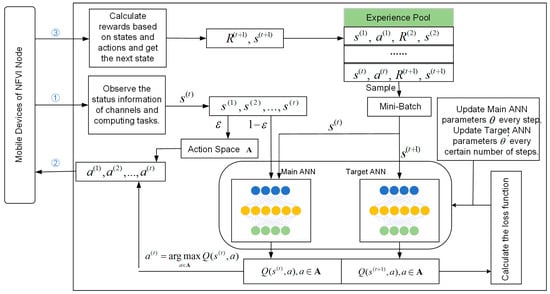
Figure 2.
The structure of the DRL-based learning algorithm.
Algorithm 2 provides the pseudocode for the DRL-based algorithm. Similar to the RL-based learning algorithm, it optimizes the long-term average reward for each episode. Steps 3–8: After observing the channel state in time slot , the -greedy strategy is executed to select an action. Steps 10–13: According to the system model, the reward is calculated, the next state is entered, and a transition sequence is formed, which is then added to the experience pool . Step 14: When the time slot index is greater than the preset size of a small batch of data , the algorithm begins to sample transition sequences from the experience pool every fixed number of steps to input into the neural network for training. Steps 15–19 are the specific training process, which has been mentioned earlier and will not be repeated here. Most of the work in the algorithm is done by the neural network itself, and our focus is on the change in average utility. When the average utility converges, it indicates that the accuracy of the neural network has been trained to a high level.
| Algorithm 2: Long-Term Average Utility Maximization Based on DRL |
|
4.3. Computational Complexity Analysis of DRL-Based Learning Algorithms
During the execution of DRL-based learning algorithms, the computation of the ANN (Artificial Neural Network) occupies the vast majority of the algorithm’s computation time. Sometimes, we need to control the number of layers and the number of neurons in each layer to reduce the computation time of the algorithm. Let represent the number of input data of the neural network, and let represent the number of neurons in the first hidden layer, second hidden layer, and output layer, respectively, where . The following conclusion can be made:
Theorem 1.
The computational complexity of estimating the current state’s Q-function and training the neural network in the training process of DRL-based algorithm is
Proof of Theorem 1.
To determine the computational complexity of the neural network, we must first understand the calculations performed within the network. The neural network parameters and consist of two components: weights and biases . According to [38], for each layer of the neural network, the following calculations are performed: . In addition, an activation function is applied to the hidden layers: . These correspond to the following two calculations:
In the feedforward calculation of the neural network, the input layer performs no computation. The first hidden layer performs matrix computations (Equation (25)) and activation function calculations (Equation (26)), with a computational complexity of , resulting in an times 1 matrix. The second hidden layer performs similar computations, with a complexity of , resulting in an times 1 matrix. The third layer, the output layer, performs matrix calculations (Equation (25)) with a complexity of , resulting in an matrix, with no activation function. In summary, the computational complexity for using the neural network is the sum of the computations of the two hidden layers and the output layer:
During algorithm training, two ANNs are used to calculate the state-action value once, so the computational complexity is . When sampling from the experience pool, each time samples are taken and input into the estimation ANN for training, the complexity is . Therefore, the computational complexity for estimating the current state’s Q-function and training the neural network is . □
5. Performance Evaluation
To demonstrate the performance of the proposed method, we consider an SDN-based MEC network with 1–8 NFVI Nodes, each serving 5 MDs, and with different geographical distributions. The distance between MDs and NFVI Nodes follows a uniform distribution in the range of [10 m, 100 m]. The computation task size is assumed to be 1 MB, requiring between 80 and 150 Megacycles of CPU cycles to complete. For each MD, the CPU frequency is 2 GHz, the transmission power is 100 mW, and the signal attenuation factor is 2. The energy consumption per CPU cycle is 10−10 J/cycle. For NFVI Nodes, similar to the performance gap between MDs and edge servers set in [11], we assume that the computing performance of the virtual MEC Server in the NFVI Node is equivalent to that of two INSPUR NE5260M5 edge servers equipped with Intel Xeon Gold 6250 processors (18 GHz), and the edge server evenly distributes computing resources to each MD. The virtual wireless access point of the NFVI Node has a total bandwidth of 10 MHz, with background noise at −100 dBm. Table 1 lists other parameters, as described in [2,11,15].

Table 1.
Model Parameters.
In the DRL-based algorithm design, we first compare the convergence performance of the algorithm under different hyperparameter settings during the training process. According to Figure 3, Figure 4 and Figure 5, we set the learning rate to 0.001, the batch size to 16, and the experience pool size to 10,000. The discount factor is set to 0.9. During the process, the initial greedy parameter is set to 0.1, and then it gradually decreases to 0.01 and remains unchanged as the algorithm iterates. For problem P2, the initial greedy parameter is set to 1, then gradually decreases to 0.01 and remains unchanged. The neural network structure consists of four layers. The first layer is the input layer; the second and third layers are hidden layers, with 10 and 100 neurons, respectively; the fourth layer is the output layer, which outputs the value of all state-action pairs. During the algorithm training process, the maximum time slot length is set to 500. Table 2 shows the specific parameter design. The simulation platform uses Python 3 with TensorFlow 1.0, and the experimental hardware is an Intel Core i5-8265U with 8 GB of RAM.
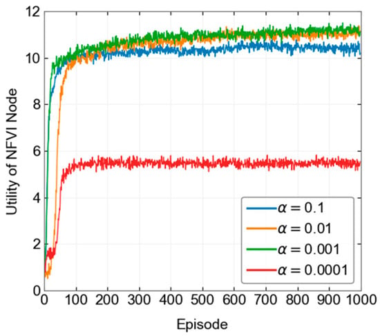
Figure 3.
Convergence process under different learning rates.
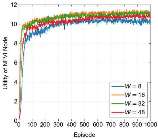
Figure 4.
Convergence process under different batch sizes.
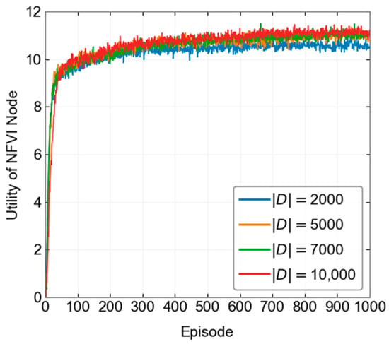
Figure 5.
Convergence process under different experience pool sizes.

Table 2.
DRL-based learning algorithm parameters.
5.1. Operator
To demonstrate the effectiveness of the above method, we propose several baseline methods. The Edge-only method is based on the DRL learning algorithm, where the time slot length is fixed at , and all MDs offload their computational tasks to virtual edge servers in the NFVI Node for processing. The experimental results for other methods are obtained with . The RLRC method modifies the ε-greedy strategy in the RL-based learning algorithm by completely switching to a random action selection strategy () during training.
Figure 6 shows the training process of the RL-based and DRL-based methods when optimizing operator utility. From the figure, it can be observed that the RL-based method starts converging around the 30th episode, while the DRL-based method starts converging around the 10th episode. In terms of convergence height, the RL-based method starts training from a value below 2 and eventually converges around 6, while the DRL-based method starts training from below 8 and converges around 11. Under the same parameter conditions, the DRL-based method performs better in both convergence height and speed compared to the RL-based method. This is because the neural network in the DRL-based learning algorithm has a stronger data processing capability than the Q-table in the RL-based algorithm, allowing it to make better decisions based on network conditions.
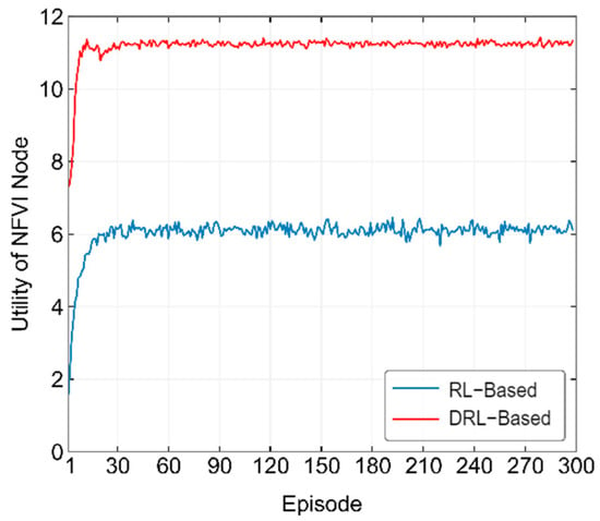
Figure 6.
Convergence process of the proposed method in optimizing operator utility.
Figure 7 compares the performance of different methods in terms of the number of CPU cycles required to complete computational tasks. From the figure, it can be seen that as continues to increase, with the time slot length remaining constant, according to Equation (10), the utility of the RLRC method gradually increases at first. However, as continues to grow, more and more computational tasks can no longer be completed within a single time slot, leading to a decline in the utility of the RLRC method. The RL-based and DRL-based methods, due to the presence of the -greedy strategy, are largely able to avoid selecting actions that would decrease the objective function, so the objective continues to increase for both methods. However, this result is obtained with . When stricter time slot length requirements are applied, the Edge-only method shows a gradual increase in the objective in the beginning, similar to the DRL-based method. However, when , the objective begins to drop sharply. This suggests that if the operator only focuses on its own utility by offloading MD computational tasks to edge servers, when the computational tasks of the MD require a large number of CPU cycles, the operator’s utility will actually decrease.
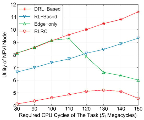
Figure 7.
Performance comparison of different methods under varying CPU cycle requirements for completing computation tasks.
Figure 8 shows the performance comparison of different methods with varying numbers of NFVI Nodes. In this experiment, we fixed Megacycles. From the figure, it can be observed that as the number of NFVI Nodes increases, the utility of all four methods increases. Specifically, the Edge-only and RLRC methods remain at relatively low levels, while the DRL-based and RL-based methods achieve optimal and sub-optimal performance, respectively. The performance of the DRL-based method is approximately 22.4% higher than that of the RL-based method. Furthermore, as the number of NFVI Nodes increases, the gap between DRL-based and RL-based methods also widens, indicating that the DRL-based method performs better in large-scale edge computing networks.
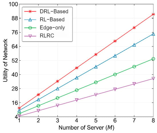
Figure 8.
Performance comparison of different methods with varying number of NFVI Nodes from operator’s pespective.
Figure 9 shows the performance comparison of different methods with varying time slot lengths. From the figure, it can be seen that when the time slot length is small, the performance of the DRL-based, RL-based, and RLRC methods is relatively poor. The RLRC method even shows negative utility in some cases. This is because when the time slot length is too small, most of the MD’s computational tasks cannot be completed within one time slot. However, as the time slot length increases, the number of computational tasks that can be completed within a time slot starts to rise, and the operator’s utility begins to increase. The performance of all three methods also starts to improve. Among them, the DRL-based method performs the best across all time slot lengths, as the actions calculated by its neural network are nearly always the optimal actions, allowing the operator to achieve the best utility.
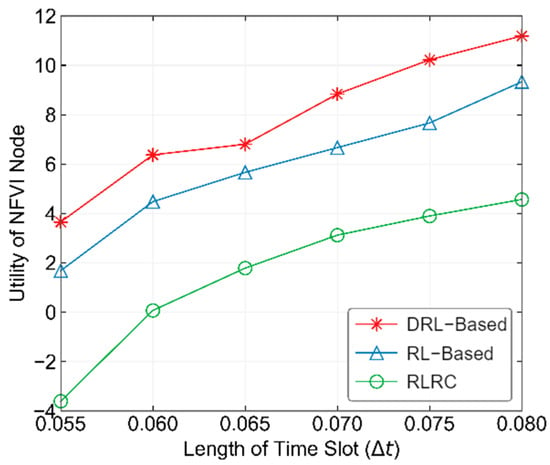
Figure 9.
Performance comparison of different methods with varying time slot lengths.
5.2. User
In solving problem P2, we also propose several baseline methods to compare and demonstrate the effectiveness of the above method. The RLRC method is as explained above. The Local-only method refers to the data obtained when all MD’s computational tasks are processed locally. The Edge-only method is based on the DRL-based method, where all computational tasks are offloaded to the edge server for processing. Since problem P2 includes the time required to complete computational tasks as part of the optimization objective, the maximum time constraint for completing computational tasks has been removed from the constraints.
Figure 10 shows the training process of the two proposed methods in optimizing user utility. From the figure, it can be observed that the RL-based method starts converging around the 40th episode, while the DRL-based method reaches its convergence height around the 20th episode, experiences a drop, and then stabilizes around the 40th episode. In terms of convergence height, both methods start training from around 7.3, with the RL-based method converging at around 8.1 and the DRL-based method converging at around 8.9. In terms of both convergence speed and height, the DRL-based method performs better than the RL-based method. Comparing the final long-term average utility (8.2133) obtained from the RL-based algorithm’s target strategy with the DRL-based algorithm’s training convergence level of 8.9, we can conclude that the DRL-based method is more suitable as an online learning algorithm, as it reaches a more ideal result during training.
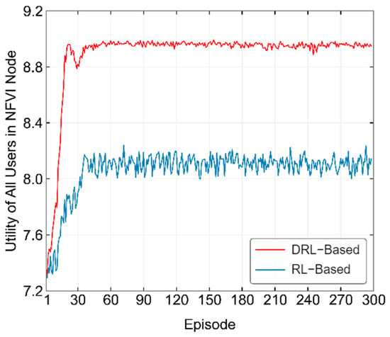
Figure 10.
Convergence process of the proposed algorithm in optimizing user utility.
Figure 11 shows the performance comparison of several methods under varying CPU cycles required to complete tasks. From the figure, it can be seen that the performance of all methods decreases as increases. This is because when the number of CPU cycles required to complete tasks increases, whether the computational tasks are offloaded to the edge server or processed locally by the MD, the utility of the MD decreases according to Equations (3), (8) and (12). On the other hand, the Local-only method performs better than the Edge-only method when , but when , the performance of the Local-only method starts to decline below that of the Edge-only method. This is because, as increases, the SDWN-Controller tends to offload the MD’s computational tasks to the edge server with more powerful computing capabilities in order to reduce the impact of MD’s energy consumption and waiting latency on user utility. This also explains why, as continues to increase, the performance of the RL-based and DRL-based methods starts to approach that of the Edge-only method. Among the methods, the DRL-based method consistently finds reasonable choices between local computation and edge computing, and allocates appropriate channel resources to each MD, which makes its performance the best among all the methods.
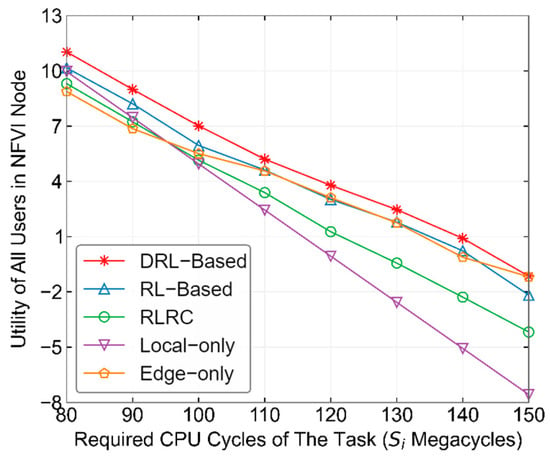
Figure 11.
Performance comparison of different methods under varying CPU cycles required to complete tasks.
Figure 12 shows the performance comparison of different methods with varying numbers of NFVI Nodes. In this experiment, we fixed Megacycles. From the figure, it can be observed that the DRL-based method has a significant advantage in optimizing the utility of the entire network’s MDs. As the number of NFVI Nodes increases, the gap between the DRL-based method and other methods grows larger, reflecting the high utility of the DRL-based method in large-scale edge computing networks. Specifically, the performance of the RL-based method improves by more than 10.8% over RLRC, and the DRL-based method improves by more than 12.2% over the RL-based method.
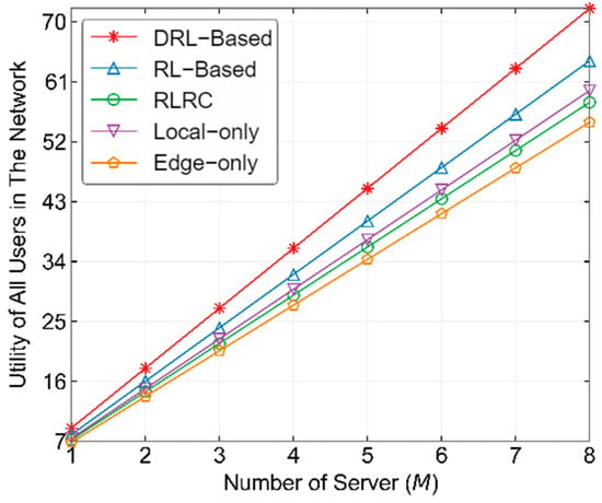
Figure 12.
Performance comparison of different methods with varying number of NFVI Nodes from user’s perspective.
Figure 13 shows the probability changes of all MDs selecting local computation or edge computing during the training process of the DRL-based method. From the figure, it can be seen that at the beginning of the algorithm training, the probability of the SDWN-Controller selecting local computation and edge computing for the MDs fluctuates around 50%. As the training progresses, the probability of MDs selecting edge computing gradually increases, while the probability of selecting local computation decreases. This is because offloading the majority of MDs’ computational tasks to virtual edge servers improves the utility of all users in the entire NFVI Node. Around the 20th episode, the probabilities of MDs selecting edge computing and local computation begin to stabilize. However, due to the continuous changes in channel states, these probabilities fluctuate within a very small range. This corresponds to the point in Figure 7 where the utility of MDs in the DRL-based method reaches its convergence level around the 20th episode and then fluctuates within a very narrow range around that level.
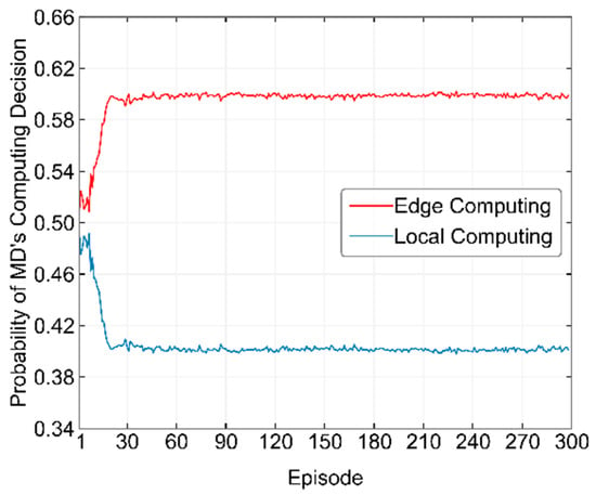
Figure 13.
Probability of MDs selecting local computation and edge computing during the training process of the DRL-based method.
6. Discussion
There are indeed some limitations behind our proposal. First, our proposal assumes the system knows the perfect CSI of all involved channels. However, a perfect CSI assumption is based on a training-based channel estimation in practice, which produces overhead and reduces spectral and energy efficiencies. Secondly, DRL models typically require extensive training in a simulated environment, and their real-world generalization may be limited by discrepancies between training and deployment conditions. Thirdly, deploying our proposed algorithm in real SDN-based MEC networks may introduce additional overhead, particularly in the SDN Controller’s operation. The controller’s real-time decision-making and interaction with network nodes could lead to latency and processing constraints. While our work primarily focuses on algorithmic efficiency in an idealized setting, we recognize the importance of evaluating system overhead and plan to explore these aspects in future work.
7. Conclusions
With the continuous advancement of 5G communication technology, MEC has evolved from a conceptual framework to real-world implementation, attracting significant attention from both academia and industry. In this paper, we propose an SDN-based MEC network architecture that integrates the latest developments in MEC and SDN to optimize offloading decisions and resource allocation. To enhance the utility of both MEC service providers and users, we formulated an optimization problem as a MDP and developed a RL-based algorithm to solve it. Recognizing the limitations of RL in handling large state spaces, we further extended the MDP state space to a continuous domain and introduced a DRL-based algorithm for improved performance. Experimental results validate the effectiveness of our proposed methods. While the RL-based algorithm enhances the long-term utility of both users and operators, the DRL-based approach achieves further improvements, increasing the utility by approximately 22.4% for operators and 12.2% for users. These findings underscore the potential of intelligent learning-based approaches in optimizing MEC networks. By offering an intelligent and scalable solution for MEC networks, this work provides valuable insights for optimizing edge computing performance and lays the foundation for future advancements in resource-efficient and adaptive MEC architectures.
Author Contributions
Conceptualization, J.S. and Y.L.; methodology, J.S. and Y.L.; validation, J.S.; formal analysis, J.S. and Y.L.; investigation, J.S. and Y.L.; resources, J.S. and Y.L.; writing—original draft preparation, J.S.; writing—review and editing, Y.L.; project administration, Y.L.; funding acquisition, Y.L. All authors have read and agreed to the published version of the manuscript.
Funding
This research was funded by the Natural Science Foundation of Zhejiang Province, grant number LZ25F020009.
Data Availability Statement
The data presented in this study are available on request from the corresponding author.
Conflicts of Interest
The authors declare no conflicts of interest.
References
- Feng, C.; Han, P.; Zhang, X.; Yang, B.; Liu, Y.; Guo, L. Computation Offloading in Mobile Edge Computing Networks: A Survey. J. Netw. Comput. Appl. 2022, 202, 103366. [Google Scholar] [CrossRef]
- Wang, X.; Li, J.; Ning, Z.; Song, Q.; Guo, L.; Guo, S.; Obaidat, M.S. Wireless Powered Mobile Edge Computing Networks: A Survey. ACM Comput. Surv. 2023, 55, 1–37. [Google Scholar] [CrossRef]
- Dong, S.; Tang, J.; Abbas, K.; Hou, R.; Kamruzzaman, J.; Rutkowski, L.; Buyya, R. Task Offloading Strategies for Mobile Edge Computing: A Survey. Comput. Netw. 2024, 254, 110791. [Google Scholar] [CrossRef]
- Gan, Q.; Li, G.; He, W.; Zhao, Y.; Song, Y.; Xu, C. Delay-Minimization Offloading Scheme in Multi-Server MEC Networks. IEEE Wirel. Commun. Lett. 2023, 12, 1071–1075. [Google Scholar] [CrossRef]
- Zheng, K.; Jiang, G.; Liu, X.; Chi, K.; Yao, X.; Liu, J. DRL-Based Offloading for Computation Delay Minimization in Wireless-Powered Multi-Access Edge Computing. IEEE Trans. Commun. 2023, 71, 1755–1770. [Google Scholar] [CrossRef]
- Yu, L.; Xu, H.; Zeng, Y.; Deng, J. Delay-Aware Resource Allocation for Partial Computation Offloading in Mobile Edge Cloud Computing. Pervasive Mob. Comput. 2024, 105, 101996. [Google Scholar] [CrossRef]
- Yang, J.; Shah, A.A.; Pezaros, D. A Survey of Energy Optimization Approaches for Computational Task Offloading and Resource Allocation in MEC Networks. Electronics 2023, 12, 3548. [Google Scholar] [CrossRef]
- Zhao, J.; Chen, M.; Pan, Y.; Sun, H.; Cang, Y.; Wang, J. Energy Minimization of the Cell-Free MEC Networks with Two-Timescale Resource Allocation. IEEE Trans. Wirel. Commun. 2024, 23, 18623–18636. [Google Scholar] [CrossRef]
- Li, T.; Li, Y.; Hu, P.; Chen, Y.; Yin, Z. Energy Minimization for IRS-and-UAV-Assisted Mobile Edge Computing. Ad Hoc Netw. 2024, 164, 103635. [Google Scholar] [CrossRef]
- Wang, L.; Li, Y.; Chen, Y.; Li, T.; Yin, Z. Air-Ground Coordinated MEC: Joint Task, Time Allocation and Trajectory Design. IEEE Trans. Veh. Technol. 2024, 74, 4728–4743. [Google Scholar] [CrossRef]
- Qin, H.; Du, H.; Wang, H.; Su, L.; Peng, Y. Multi-Objective Optimization for NOMA-Based Mobile Edge Computing Offloading by Maximizing System Utility. China Commun. 2023, 20, 156–165. [Google Scholar] [CrossRef]
- Liu, B.; Peng, M. Online Offloading for Energy-Efficient and Delay-Aware MEC Systems with Cellular-Connected UAVs. IEEE Internet Things J. 2024, 11, 22321–22336. [Google Scholar] [CrossRef]
- An, X.; Li, Y.; Chen, Y.; Li, T. Joint Task Offloading and Resource Allocation for Multi-User Collaborative Mobile Edge Computing. Comput. Netw. 2024, 250, 110604. [Google Scholar] [CrossRef]
- Li, Y.; Li, Y.; Chen, Y.; Tong, J.; Tian, X.; Chi, K. Online Resolution Adaptation and Resource Allocation for Edge-Assisted Video Analytics. Comput. Netw. 2024, 244, 110342. [Google Scholar] [CrossRef]
- Chen, Y.; Li, Y.; Chen, C.S.; Chi, K. Exploring Long-Term Commensalism: Throughput Maximization for Symbiotic Radio Networks. IEEE Trans. Mob. Comput. 2025, 24, 2376–2393. [Google Scholar] [CrossRef]
- Miao, L.; Li, S.; Wu, X.; Liu, B. Mean-Field Stackelberg Game-Based Security Defense and Resource Optimization in Edge Computing. Appl. Sci. 2024, 14, 3538. [Google Scholar] [CrossRef]
- Al-Hammadi, I.; Li, M.; Islam, S.M.; Al-Mosharea, E. Collaborative Computation Offloading for Scheduling Emergency Tasks in SDN-Based Mobile Edge Computing Networks. Comput. Netw. 2024, 238, 110101. [Google Scholar] [CrossRef]
- Zhang, Y.; Li, Y.; Chen, B.; Li, E.; Zheng, K.; Chi, K.; Zhu, Y.-H. Design of an RFID-Based Self-Jamming Identification and Sensing Platform. IEEE Trans. Mob. Comput. 2024, 23, 3802–3816. [Google Scholar] [CrossRef]
- Du, J.; Jiang, C.; Benslimane, A.; Guo, S.; Ren, Y. SDN-Based Resource Allocation in Edge and Cloud Computing Systems: An Evolutionary Stackelberg Differential Game Approach. IEEE/ACM Trans. Netw. 2022, 30, 1613–1628. [Google Scholar] [CrossRef]
- Chen, G.; Chen, Y.; Mai, Z.; Hao, C.; Yang, M.; Du, L. Incentive-Based Distributed Resource Allocation for Task Offloading and Collaborative Computing in MEC-Enabled Networks. IEEE Internet Things J. 2022, 10, 9077–9091. [Google Scholar] [CrossRef]
- Wang, X.; Han, Y.; Leung, V.C.; Niyato, D.; Yan, X.; Chen, X. Convergence of Edge Computing and Deep Learning: A Comprehensive Survey. IEEE Commun. Surv. Tutor. 2020, 22, 869–904. [Google Scholar] [CrossRef]
- Huang, L.; Bi, S.; Zhang, Y.-J.A. Deep Reinforcement Learning for Online Computation Offloading in Wireless Powered Mobile-Edge Computing Networks. IEEE Trans. Mob. Comput. 2020, 19, 2581–2593. [Google Scholar] [CrossRef]
- Zhang, S.; Gu, H.; Chi, K.; Huang, L.; Yu, K.; Mumtaz, S. DRL-Based Partial Offloading for Maximizing Sum Computation Rate of Wireless Powered Mobile Edge Computing Network. IEEE Trans. Wirel. Commun. 2022, 21, 10934–10948. [Google Scholar] [CrossRef]
- Tan, L.; Kuang, Z.; Zhao, L.; Liu, A. Energy-Efficient Joint Task Offloading and Resource Allocation in OFDMA-Based Collaborative Edge Computing. IEEE Trans. Wirel. Commun. 2022, 21, 1960–1972. [Google Scholar] [CrossRef]
- Li, X.; Fan, R.; Hu, H.; Zhang, N.; Chen, X.; Meng, A. Energy-Efficient Resource Allocation for Mobile Edge Computing with Multiple Relays. IEEE Internet Things J. 2021, 9, 10732–10750. [Google Scholar] [CrossRef]
- Xu, D. Device Scheduling and Computation Offloading in Mobile Edge Computing Networks: A Novel NOMA Scheme. IEEE Trans. Veh. Technol. 2024, 73, 9071–9076. [Google Scholar] [CrossRef]
- Li, B.; Si, F.; Zhao, W.; Zhang, H. Wireless Powered Mobile Edge Computing with NOMA and User Cooperation. IEEE Trans. Veh. Technol. 2021, 70, 1957–1961. [Google Scholar] [CrossRef]
- Mao, Y.; You, C.; Zhang, J.; Huang, K.; Letaief, K.B. A Survey on Mobile Edge Computing: The Communication Perspective. IEEE Commun. Surv. Tutor. 2017, 19, 2322–2358. [Google Scholar] [CrossRef]
- Mao, B.; Tang, F.; Fadlullah, Z.M.; Kato, N.; Akashi, O.; Inoue, T.; Mizutani, K. A Novel Non-Supervised Deep-Learning-Based Network Traffic Control Method for Software Defined Wireless Networks. IEEE Wirel. Commun. 2018, 25, 74–81. [Google Scholar] [CrossRef]
- Chiosi, M.; Clarke, D.; Willis, P.; Reid, A. Network Functions Virtualization Introductory White Paper. In Proceedings of the SDN and OpenFlow World Congress, Darmstadt, Germany, 22–24 October 2012; pp. 1–16. [Google Scholar]
- Open Networking Foundation. Software-Defined Networking: The New Norm for Networks. 2012. Available online: https://opennetworking.org (accessed on 10 February 2025).
- Xue, J.; Wang, L.; Yu, Q.; Mao, P. Multi-Agent Deep Reinforcement Learning-Based Partial Offloading and Resource Allocation in Vehicular Edge Computing Networks. Comput. Commun. 2025, 234, 108081. [Google Scholar] [CrossRef]
- Liu, J.; Wang, Y.; Pan, D.; Yuan, D. QoS-Aware Task Offloading and Resource Allocation Optimization in Vehicular Edge Computing Networks via MADDPG. Comput. Netw. 2024, 242, 110282. [Google Scholar] [CrossRef]
- Open Networking Foundation. OpenFlow Switch Specification (Version 1.5.1); ONF TS-025: Menlo Park, CA, USA, 2015; Available online: http://www.opennetworking.org (accessed on 10 February 2025).
- Luo, Q.; Li, C.; Luan, T.H.; Shi, W. Collaborative Data Scheduling for Vehicular Edge Computing via Deep Reinforcement Learning. IEEE Internet Things J. 2020, 7, 9637–9650. [Google Scholar] [CrossRef]
- Sutton, R.S.; Barto, A.G. Reinforcement Learning: An Introduction, 2nd ed.; MIT Press: Cambridge, MA, USA, 2018. [Google Scholar]
- Melo, F.S. Convergence of Q-Learning: A Simple Proof. Institute for Systems and Robotics, USA. [Online]. Available online: https://welcome.isr.tecnico.ulisboa.pt/ (accessed on 10 February 2025).
- Hochreiter, S.; Schmidhuber, J. Long Short-Term Memory. Neural Comput. 1997, 9, 1735–1780. [Google Scholar] [CrossRef] [PubMed]
Disclaimer/Publisher’s Note: The statements, opinions and data contained in all publications are solely those of the individual author(s) and contributor(s) and not of MDPI and/or the editor(s). MDPI and/or the editor(s) disclaim responsibility for any injury to people or property resulting from any ideas, methods, instructions or products referred to in the content. |
© 2025 by the authors. Licensee MDPI, Basel, Switzerland. This article is an open access article distributed under the terms and conditions of the Creative Commons Attribution (CC BY) license (https://creativecommons.org/licenses/by/4.0/).