Abstract
Orthogonal time–frequency space (OTFS) modulation combined with massive multiple-input multiple-output (MIMO) can simultaneously address the problems caused by multipath delay, the Doppler effect, and channel fading. To mitigate inter-subcarrier and inter-symbol interference in satellite–terrestrial MIMO-OTFS systems, an iterative maximum ratio combining detection algorithm based on hard-decision interference cancelation (ICH-IMRC) is proposed. The signal detection is iterated by performing MRC on the interference-canceled received symbols. To mitigate the error spread in the interference cancelation process, iterative maximum ratio combining detection based on soft symbol interference cancelation (S-IMRC) is proposed, which is improved based on ICH-IMRC. The interference cancelation is updated by the expectation of other symbols, and the expectation and variance of symbols are updated by soft judgment with the posterior probability of symbols. To improve the detection convergence speed, optimal relaxation parameters are obtained based on the Sparrow Search Algorithm (SSA). Simulation results show that the proposed S-IMRC has superior error rate performance compared to the conventional algorithms for satellite–terrestrial MIMO-OTFS systems. Furthermore, the proposed algorithm is applicable to various satellite channel models and achieves excellent BER for different orders of orthogonal amplitude-modulated signals and different antenna array sizes.
1. Introduction
The 6G mobile communication network achieves seamless global coverage, supports all emerging full-spectrum applications for the vision of reliable communications, and aims for terrestrial and non-terrestrial nodes through the fusion of converged networks to meet the integration of space, air, ground, and sea [1,2]. As the main part of the space-based network, LEO satellite communication has the advantages of less influence from the ground, wide coverage, etc., and is regarded as one of the most promising solutions to realize the seamless connection among space, air, ground, and sea [3,4]. However, there are numerous complex situations in LEO satellite mobile communication. The high movement speed of LEO satellites relative to the ground, complex channel characteristics, short transit time, and continuously changing elevation angles can lead to problems such as time-domain non-stationarity, large Doppler spread, and severe fading in LEO satellite mobile communication channels [5,6,7].
As an emerging modulation technique, OTFS is able to effectively cope with the delay–Doppler effect caused by the high-speed movement of LEO satellites through processing signals in the delay–Doppler (DD) domain, which makes full use of the diversity in the time and frequency domains [8,9,10,11]. For signal detection of OTFS systems, Jia Shi et al. introduced the fundamentals of the OTFS scheme and discussed the feasibility and advantages of applying OTFS to LEO-SAT communication. In addition, OTFS-based LEO-SAT transmission and DD-domain-based orthogonal approximate message passing detection schemes are proposed to iteratively eliminate the inter-symbol interference effect and suppress the noise effect in the DD domain [12]. Tharaj Thaj et al. proposed a nonlinear complexity iterative rake detection algorithm for OTFS modulation based on the MRC scheme, which reduces complexity by employing a low-complexity single-tap minimum mean square error (MMSE) equalizer in the time–frequency domain to obtain an initial estimate of the OTFS symbols [13]. For LEO satellite scenarios, many scholars have proposed corresponding solutions for signal detection in satellite OTFS systems. Yue Li et al. proposed a communication and navigation integrated scheme based on OTFS for LEO satellite communication. The modulated communication signals and dual-code alternating binary-offset-carrier-modulated navigation ephemeris signals is superposed in the power domain and the superposed signals are separated using a serial interference cancelation detector [14]. Tianshi Li et al. proposed an MMSE-based sequential detection algorithm in a satellite-to-ground channel at sub-6 GHz and millimeter-wave bands with high mobility using a sequential interference cancelation technique for symbol detection to improve BER performance [15].
The above algorithms and many other excellent works provide a solid foundation for single-input single-output (SISO) OTFS transceiver design. Considering the massive multiple-input multiple-output (MIMO) technique with diversity performance, it can effectively enhance the robustness of the signal [16,17]. Therefore, combining MIMO with OTFS in satellite communication systems is also a technique worth investigating [18,19,20,21]. Communication reliability is a key factor in evaluating communication networks [22,23]. To enhance the reliability of the MIMO-OTFS communication system, domestic and foreign scholars have conducted a lot of research. Xianda Wu et al. proposed a tensor-based orthogonal matching pursuit (OMP) channel estimation algorithm by exploiting the channel sparsity in the DD domain to significantly reduce the complexity of channel estimation [24]. Dan Feng et al. proposed a scheme based on generalized exponential modulation for MIMO-OTFS systems to enhance performance and spectral efficiency and also proposed a two-stage detection algorithm to reduce complexity [25]. Tharaj Thaj et al. proposed a low-complexity detector for OTFS-MIMO-based systems. The transmitted symbol vectors received through different diversity branches are linearly combined using the MRC technique to iteratively improve the ratio of signal to interference plus noise at the output of the combiner [26]. Ding Shi et al. proposed a channel state information (CSI) capture scheme for massive MIMO-OTFS systems with fractional Doppler to minimize pilot overhead and improve the accuracy of the system, incorporating deterministic frequency pilot design and a channel estimation algorithm [27]. Xuefeng Li et al. proposed a structured sparsity adaptive matching tracking algorithm for MIMO-OTFS channel estimation without the a priori information of channel sparsity K and further proposed an improved SSAMP algorithm to enhance the channel estimation accuracy and reconstruction speed [28].
To improve the accuracy of signal detection for satellite–terrestrial MIMO-OTFS systems, the iterative maximum ratio combining detection algorithm based on hard-decision interference cancelation (ICH-IMRC) is proposed. The IMRC detection based on soft-symbol interference cancelation (S-IMRC) is proposed to mitigate the error propagation caused by interference cancelation so that the accuracy and reliability of the overall system can be further improved. The main contributions of the paper are summarized below.
- A satellite–terrestrial downlink MIMO-OTFS system is constructed for NTN-TDL-A, NTN-TDL-B, NTN-TDL-C, NTN-TDL-D channel models under the 3GPP TR 38.811 standard, antenna arrays of different sizes, and different modulation orders.
- An iterative maximum ratio combining detection algorithm based on hard-decision interference cancelation (ICH-IMRC) is proposed, which performs signal detection in the delay–Doppler (DD) domain. In each iteration, interference cancelation is performed on the symbols followed by MRC detection, and the estimated signal is output by the hard judgment. Relaxation parameters are introduced for the hard judgment of the symbols to improve the convergence speed.
- An iterative maximum ratio combining detection algorithm based on soft-symbol interference cancelation (S-IMRC) is proposed. The detection symbols are updated by performing IMRC detection on received symbols that are already interference-canceled, where interference cancelation is performed using the expectations of the other symbols. Next, the estimated signal is soft-judged based on maximum-likelihood estimation. Due to the influence of the relaxation parameters on the BER of the system, the optimal relaxation parameters are obtained with the Sparrow Search Algorithm (SSA) to further improve system reliability.
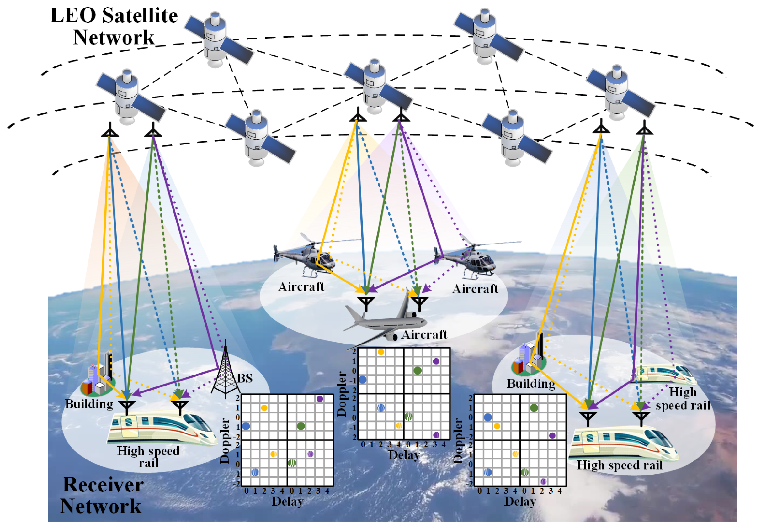
2. MIMO-OTFS System Model and Transmit–Receive Structure
In this section, a scenario model of the satellite–terrestrial downlink based on MIMO-OTFS is designed. Then, the channel model and the input–output relationship of the signals for the MIMO-OTFS system are presented.
2.1. MIMO-OTFS System Model
Consider a system model based on MIMO-OTFS for satellite–terrestrial downlinks, as shown in Figure 1, which consists of a LEO satellite network and a receiver network. As the transmitter, the LEO satellite is equipped with antennas. The receiver network mainly consists of high-speed mobile terminals such as high-speed rail and aircraft. Each terminal is equipped with antennas, where the solid and dotted lines represent the signals received by the different antennas of the terminal. Within the single-beam coverage of each antenna for the LEO satellite, the LEO satellite achieves downlink communication with the terminal. During the transmission process, the signal reflects off of objects such as buildings on the ground or other high-speed mobile terminals, creating multiple propagation paths. Multipath propagation includes straight line-of-sight (LoS) propagation paths (i.e., blue and green straight lines), as well as a collection of delayed and Doppler-shifted scattered echoes of the transmitted signals (i.e., yellow and violet broken lines). In order to visually demonstrate the multipath characteristics of the channel model for MIMO-OTFS systems, a delay–Doppler grid is used to quantify the delay, Doppler shift, and path gain in the multipath signal. In the delay–Doppler grid, the black boxes indicate the channel characteristics between different transmitting antennas and different receiving antennas. Each colored point in the delay–Doppler grid corresponds to a propagation path represented by the same colored rays at a given moment in time. The area of the points in the delay–Doppler grid represents the gain of each propagation path.
Figure 1.
The system model based on MIMO-OTFS for satellite–terrestrial downlinks.
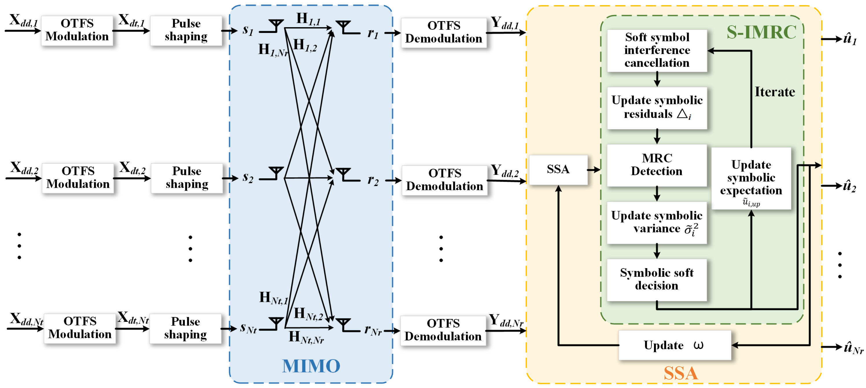
2.2. MIMO-OTFS Transmitter
The transmit signal from the -th antenna of the LEO satellite is modulated by -QAM to obtain the complex modulated signal , where denotes the number of modulation orders. The modulated signal is placed on a -dimensional 2D delay–Doppler grid to generate OTFS frames in the delay–Doppler domain . M is the dimension of the delay domain and also represents the number of subcarriers. N is the dimension of the Doppler domain and also represents the number of multicarrier signals. Inverse Symplectic Finite Fourier Transform (ISFFT) converts each OTFS frame in the DD domain to the time–frequency domain (TF), and the signal matrix in the TF domain can be written as:
where and denote the matrices of M-point Discrete Fourier Transform (DFT) and N-point Inverse Discrete Fourier Transform (IDFT), respectively. The Heisenberg transform converts the signal in the TF domain to the delay–time (DT) domain, and the signal matrix in the DT domain can be written as:
is rectangular pulse shaped and vectorized by the transmitter to obtain the time-domain discrete baseband vector and can be written as:
where is the transmitting waveform matrix. The transmitter adopts a rectangular pulse-shaping waveform, and can be characterized by the M-order identity matrix . “⨂” denotes the Kronecker product. denotes the matrix of size transformed into a one-dimensional vector of size .
In the MIMO-OTFS system, each transmitting antenna transfers different time-domain signals, and denotes the time-domain signals of the -th transmitting antenna. The total transmit signal splices the signals from each antenna row by row and can be written as:
2.3. MIMO-OTFS Receiver
After transmission over the fast time-varying channel, the vector expression of the received signal in the time domain is:
where , denotes the additive Gaussian noise in the time domain with noise power of . is the MIMO channel matrix in the time domain, which is expressed as:
where denotes the time-domain channel matrix between the -th transmitter antenna and the -th receiver antenna, which is expressed as:
where denotes the number of propagation paths between the -th transmitter antenna and the -th receiver antenna, and denote the indexes of the delay and Doppler axes for the p-th path on the delay–Doppler grid, respectively, and denotes the complex channel gain for the p-th path. and represent the forward cyclic shift matrix and the diagonal matrix, respectively. and are expressed as:
where . The effective channel matrix in the DD domain with rectangular pulse as the received waveform can be expressed as [29]:
where is the receiving waveform matrix. Corresponding to the transmitter, the receiver also adopts a rectangular pulse shaping waveform, and can be characterized by the M-order identity matrix . The effective MIMO-OTFS channel matrix in the DD domain can be expressed as:
According to the inverse process at the transmitter side, the received signal in the DD domain is expressed as:
where , , .
3. Iterative Maximum Ratio Merger Detection Based on Symbol Interference Cancelation
In this section, an iterative MRC algorithm based on hard-decision interference cancelation (ICH-IMRC) is proposed for satellite– terrestrial MIMO-OTFS systems. After interference cancelation of the received symbols at each iteration, MRC detection is performed in the DD domain and the estimated symbols are updated by hard judgment. To reduce the error propagation of imperfect interference cancelation, the IMRC algorithm based on soft-symbol interference cancelation (S-IMRC) is proposed. The optimal relaxation parameters are obtained based on the SSA to accelerate the convergence speed. The remainder of this section describes the proposed algorithm in detail.
3.1. IMRC Detector Based on Hard-Decision Interference Cancelation
The MRC receiver maximizes the power of the received signal and improves the system’s resistance to multipath fading and interference through effective signal combining and enhancement. Therefore, IMRC detection based on hard-decision interference cancelation (ICH-IMRC) in the DD domain is proposed.
During MRC detection of the current modulation symbol, other symbols are considered as interference and cancelation is performed. The detection value of the i-th transmitted symbol obtained by the ICH-IMRC algorithm can be given by the following equation:
where denotes the j-th column of . is the hard judgment output of the j-th modulated symbol. To improve the convergence speed, the relaxation parameter is introduced to optimize the hard judgment output, which is given by the following equation:
where denotes the hard judgement process, i.e., the direct judgement of the received signal according to its judgement threshold.
Performing a single MRC signal detection may not achieve sufficient accuracy. IMRC detection can significantly improve the detection accuracy of received signals by iteratively estimating the received symbols.
3.2. IMRC Detector Based on Soft-Symbol Interference Cancelation
To reduce the error propagation during the iterative process, an IMRC detector based on soft symbol interference cancelation (S-IMRC) is proposed. The framework of the S-IMRC algorithm is shown in Figure 2. The algorithm is performed by achieving IMRC detection after interference cancelation of the received symbols by using the expectation of the other symbols. The posterior probability of the symbol is obtained by soft judgment. The expectation and variance of the soft symbols for the next iteration are then updated by the posterior probability of the symbol.
Figure 2.
The framework of the S-IMRC algorithm.
The detection value of the i-th transmitted symbol obtained by the S-IMRC algorithm can be given by the following equation:
where achieves symbol-wise soft interference cancelation. Let , , and denote all the soft symbols, as well as the expectation and variance of the symbols to be estimated, respectively. The expressions for the expectation of the j-th soft symbol are calculated as follows:
where is denoted as the set of -order modulated symbols and a denotes one of the modulated symbols in . The expectation of soft symbols contains information about all -order modulated symbols , mitigating the effect of error spreading in interference cancelation. Therefore, the reliability performance of the S-IMRC detector is improved compared to the ICH-IMRC detector.
The a posterior probability of the i-th modulated symbol, which is based on the maximum likelihood estimation, can be expressed as:
The judgment of the estimated symbol is updated by
where represents the probability density, which can be expressed as:
where denotes the i-th soft symbol, which introduces the relaxation parameter to increase the convergence rate.
And represents the variance of the i-th soft symbol , which can be expressed as:
The S-IMRC detection effectively improves the accuracy of the system by iteratively updating the expectation and variance of the symbols and constantly approximating the true value. The iteration structure of the proposed S-IMRC is demonstrated in Algorithm 1, where the maximum number of iterations T is indicated.
| Algorithm 1 S-IMRC detector |
|
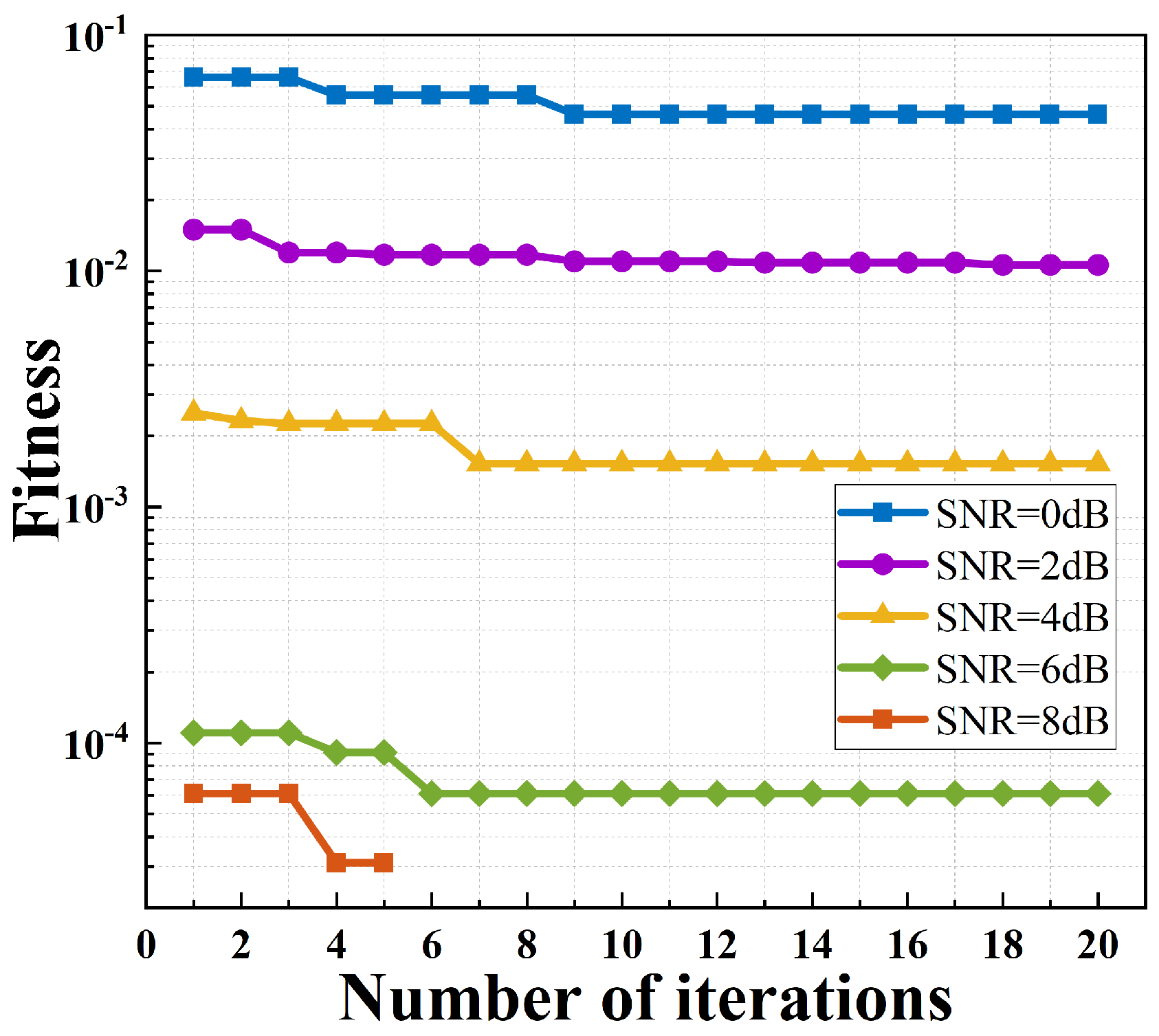
3.3. SSA-Based Optimal Relaxation Parameters
The relaxation parameter has an important effect on the convergence rate, so it is crucial to find the optimal relaxation parameter . Considering that the SSA has the global search capability of fast convergence, the SSA is adopted to seek the optimal slack parameter . The SSA model performs a global optimal search by simulating the foraging strategy of a sparrow population, which contains the explorer, follower, and alerter. Here, each sparrow represents a relaxation parameter value .
During each iterative search, the explorer, follower, and alerter are initialized within the range of relaxation parameters and these parameters are substituted into the S-IMRC detection algorithm to calculate the BER (i.e., fitness). After sorting according to the fitness, the follower adjusts the parameters within the safe region to extend the search range and avoid repeated searches; the alerter monitors the region to prevent falling into local optimum; and the explorer continuously updates the parameters and calculates the fitness. The explorer is updated as:
where denotes the number of the current iteration. denotes the p-th relaxation parameter value at the t-th iteration. denotes a random number. denotes the maximum number of iterations. Q denotes a random number obeying a normal distribution. L denotes a -dimensional all-1 vector. denotes the alarm value. denotes the safety threshold. The follower obtains the new relaxation parameter by following the explorers with the optimal fitness value, which is updated as follows:
where P denotes the total number of relaxation parameters. denotes the best relaxation parameter in the current explorers. denotes the current global worst relaxation parameter value. A represents a dimensional vector with each element randomly assigned a value of either 1 or −1. The alerter is responsible for monitoring the region of the relaxation parameter. The expression for updating the alerter is as follows:
where denotes the current global best relaxation parameter value. denotes the step control parameter. denotes a random number, which controls the variation of the relaxation parameter value. represents a very small value that is not zero. The fitness represents the BER of the system for the corresponding relaxation parameter value. denote the current relaxation parameter value’s fitness value, the current global optimal fitness value, and the current global worst fitness value, respectively.
In each iteration, the relaxation parameter values are updated, and the fitness is calculated. The optimal relaxation parameter value is obtained based on the SSA by gradually approximating the optimal solution until the preset stopping condition is satisfied.
4. Results and Performance Analyses
In this section, the simulation parameters for the LEO satellite downlink MIMO-OTFS system are presented. The complexity of the ICH-IMRC and S-IMRC algorithms and the analysis of simulation results are demonstrated.
4.1. Simulation Parameters
In this paper, the channel models are adopted from the NTN-TDL-A, NTN-TDL-B, NTN-TDL-C, and NTN-TDL-D models in the S-band (2.2 GHz) under the 3GPP TR 38.811 standard [30] and are specifically designed for non-terrestrial network (NTN) scenarios to accurately represent the LEO satellite–terrestrial signal propagation environment. The delay, power gain parameters, and fading distribution of the channel models are shown in Table 1.
Table 1.
Parameters of the channel models.
Furthermore, the S-band frequency of 2.2 GHz is selected due to its favorable propagation characteristics, including reduced rain attenuation and adequate bandwidth for LEO satellite–terrestrial communication scenarios. Considering the distance loss and the communication band, the SNR is set between 0 dB and 18 dB in steps of 2 dB increments, and the system is simulated sequentially. The size of the antenna array () for MIMO is . In OTFS modulation, the number of subcarriers is set to , the number of time slots is set to , and the modulation mode is = 4/16-QAM. The main system model parameters are referenced in Table 2.
Table 2.
Parameter settings in the system model.
4.2. Complexity Analysis
In this section, the computational complexity of the comparison algorithms, the proposed ICH-IMRC, S-IMRC and SSA-based S-IMRC are described, respectively.
To validate the effectiveness of the S-IMRC algorithm, it is compared with the minimum mean square error (MMSE) algorithm, the message passing (MP) algorithm and the IMRC algorithm. For the computational complexity of the comparison algorithms, the computational complexity of the MP algorithm focuses on updating the maximum-likelihood probability of each symbol. Therefore, the overall complexity of the MP algorithm is , where is the maximum number of iterations to perform the MP algorithm. The computational complexity of the MMSE algorithm is mainly focused on the operation of the channel matrix, and its complexity is . The overall computational complexity of the IMRC algorithm is , where is the maximum number of iterations to perform the MRC algorithm.
For the computational complexity of the proposed algorithms, the computational complexity of ICH-IMRC is mainly symbol-level interference cancelation and hard judgment with . The proposed S-IMRC detector mainly includes the computations of , , and . can be updated with the maximum complexity of for all iterations. can be updated with the complexity of for all iterations. At last, the computations of maximum-likelihood estimation are with the complexity of . In summary, the computational complexity of S-IMRC is , and the computational complexity of SSA-based S-IMRC is .
4.3. Simulation Results and Analysis
Figure 3 presents the NTN-TDL-B channel model in the DD domain for the MIMO-OTFS system with an antenna array of and at SNR = 0 dB. The channel model in the DD domain is presented in the form of a two-dimensional impulse response, which can describe the path parameters between all the transceiver antennas, including the number of paths, the path gain, the delay interval, and the Doppler interval.
Figure 3.
NTN-TDL-B channel model in the DD domain for MIMO-OTFS systems.
The fitness curves of the SSA visually demonstrate the convergence effect of obtaining optimal relaxation parameters. Figure 4 illustrates the convergence trend of the fitness of the SSA to obtain the optimal relaxation parameters in the S-IMRC algorithm for different SNRs. The simulation parameters for Figure 4, Figure 5 and Figure 6 are set as follows: the size of the antenna array is , , the NTN-TDL-B channel model is selected, and the modulation order is 4-QAM. The fitness of the SSA is inversely correlated with the accuracy of S-IMRC-based signal detection. As the fitness decreases, the accuracy of S-IMRC-based signal detection gradually improves, so it can be inferred that the SSA effectively optimizes the optimal relaxation parameters. In the whole iterative process, the fitness reaches the minimum value at the ninth iteration and tends to be stable, which indicates that the SSA has the advantages of fast convergence speed and good stability. With the increase in the SNR, the fitness gradually decreases. The S-IMRC algorithm based on SSA optimization achieves nearly perfect detection at SNR = 8 dB.
Figure 4.
Convergence trend of fitness based on SSA.
Figure 5.
Iterative convergence trend of BER for S-IMRC.
Figure 6.
BER for different detection algorithms.
Table 3 demonstrates the optimal relaxation parameter values of the S-IMRC algorithm obtained based on the SSA for different modulation orders and antenna array sizes.
Table 3.
Optimal relaxation parameter values obtained based on SSA.
Figure 5 illustrates the iterative convergence trend of the BER based on S-IMRC. With the increase in SNR, the BER of the S-IMRC algorithm decreases gradually. As the number of iterations increases, the BER of the S-IMRC algorithm decreases rapidly and then stabilizes. It shows that the S-IMRC algorithm improves the BER performance through iterative step-by-step optimization. As can be seen overall, the S-IMRC algorithm achieves the optimal BER after 12 iterations.
Figure 6 illustrates the BER of different detection algorithms for MIMO-OTFS systems. The iteration number of the S-IMRC algorithm is set to 12. In terms of BER performance, the ranking of different detection algorithms from the best to the worst is as follows: S-IMRC, ICH-IMRC, MP, MMSE, and IMRC. The S-IMRC algorithm exhibits optimal BER performance under all SNR conditions. The ICH-IMRC algorithm closely follows with relatively better overall performance. Following these are the MP and MMSE algorithms, which show moderate performance. The IMRC algorithm performs inferiorly to the above algorithms and gives the worst BER for all SNR conditions. When the BER reaches , the BER performance of S-IMRC is improved by 1.5 dB, 2.7 dB, 8.4 dB, and 13.2 dB compared to ICH-IMRC, MP, MMSE, and IMRC, respectively. It can be seen that the S-IMRC algorithm shows excellent signal detection. The reason for this is that soft-symbol interference cancelation and soft judgment mitigate the effect of error spreading. Moreover, optimal relaxation parameters are obtained based on the SSA to minimize the BER of the system.
Figure 7 illustrates the BER of IMRC, ICH-IMRC and S-IMRC detection algorithms for 4-QAM and 16-QAM modulation modes. The solid and dashed lines represent the 4-QAM and 16-QAM modulation modes, respectively. The simulation parameters are set as follows: the size of the antenna array is , , the NTN-TDL-B channel model is selected, and the iteration number of the S-IMRC algorithm is set to 12. Due to the various constraints of satellite–terrestrial downlink communications such as channel conditions, transmit power, hardware complexity, etc., the best balance between spectral efficiency and system performance needs to be found. Therefore, low- and medium-order modulation methods (e.g., 4-QAM, 16-QAM) are usually a more practical and reliable choice. Both the proposed ICH-IMRC and S-IMRC are applicable to different modulation orders. The S-IMRC detection performance is excellent in both 4-QAM and 16-QAM modulation, followed by the ICH-IMRC algorithm, and the IMRC algorithm performs the worst. The BER of the detection algorithm becomes worse as the modulation order increases. It reflects that lower-order modulation has better noise immunity under the same conditions. For the S-IMRC algorithm, the BER for 4-QAM is improved by 8.2 dB compared to 16-QAM.
Figure 7.
BER of different detection algorithms for different modulation orders.
Figure 8 shows the BER of ICH-IMRC and S-IMRC with different channel models. The simulation parameters are set as follows: the size of the antenna array is , , the modulation mode is 4-QAM, and the iteration number of the S-IMRC algorithm is set to 12. The solid and dashed lines represent S-IMRC and ICH-IMRC algorithms, respectively. The effect of different channel models on the performance of detection algorithms is significant. This is because different channel models have different multipath effects, delay extension, and Doppler shift characteristics that affect the difficulty of signal detection. The performance of the channel models from best to worst is as follows: NTN-TDL-B, NTN-TDL-A, NTN-TDL-D, NTN-TDL-C. Moreover, the ICH-IMRC and S-IMRC algorithms can be applied to various satellite channel models, demonstrating broad applicability.
Figure 8.
BER of ICH-IMRC and S-IMRC with different channel models.
Figure 9 demonstrates the BER of the S-IMRC algorithm with 4-QAM and 16-QAM modulation modes for different antenna array configurations . The simulation parameters are set as follows: , and the iteration number of the S-IMRC algorithm is set to 12. The solid and dashed lines represent the 4-QAM and 16-QAM modulation modes, respectively. When the modulation mode is 4-QAM, the S-IMRC algorithm’s BER for the (16, 16) antenna array improves by 0.83 dB and 12.1 dB compared to the (8, 8) and (2, 2) antenna arrays, respectively. As the size of the antenna array increases, the BER decreases significantly and shows better anti-interference capability. The reason for this is that the transmitted signal propagates through multiple antenna paths, and the multiple signals are received and combined to effectively improve the SNR and detection performance.
Figure 9.
BER of S-IMRC with different antenna arrays.
5. Conclusions
In this paper, the application of an iterative MRC signal detection algorithm based on interference cancelation is investigated for satellite–terrestrial MIMO-OTFS networks. An iterative maximum ratio combining detection algorithm based on hard-decision interference cancelation (ICH-IMRC) is proposed by performing iterative MRC detection for received symbols in the DD domain with interference cancelation. To mitigate the error propagation caused by interference cancelation, the IMRC detection based on soft-symbol interference cancelation (S-IMRC) is proposed. Simulation results show that the proposed algorithm significantly reduces the BER compared with the traditional MP, MMSE, and IMRC algorithms. Moreover, the proposed S-IMRC algorithm is widely applicable to various satellite channel models, and it maintains an excellent BER for different orders of quadrature amplitude modulation signals and different sizes of antenna array configurations, ensuring the high reliability of communication quality.
Author Contributions
Conceptualization, M.S. and Q.Z.; methodology, M.S.; software, M.S. and J.L.; validation, R.G. and L.L.; formal analysis, W.F.; investigation, W.F. and X.L. (Xiaohu Li); resources, M.S.; data curation, F.W.; writing—original draft preparation, X.L. (Xiangyu Liu); writing—review and editing, M.S. and Q.T.; visualization, Y.Z.; supervision, Q.Z. and F.T.; project administration, H.Y. and Y.W.; funding acquisition, Q.Z. All authors have read and agreed to the published version of the manuscript.
Funding
This work was supported in part by the National Key Research and Development Program of China under Grant 2022YFB2902502; in part by the National Natural Science Foundation of China (NSFC) under Grant 61835002, Grant 62325203, and Grant U22B2033; in part by Program for Youth Innovative Research Team of BUPT NO. 2024YQTD02.
Data Availability Statement
The data are unavailable due to privacy or ethical restrictions.
Conflicts of Interest
The authors declare no conflicts of interest.
References
- Sun, M.; Zhang, Q.; Yao, H.; Gao, R.; Zhao, Y.; Guizani, M. Resource Allocation and Deep Learning-Based Joint Detection Scheme in Satellite NOMA Systems. IEEE Trans. Wirel. Commun. 2024, 24, 526–539. [Google Scholar] [CrossRef]
- Wang, C.-X.; Huang, J.; Wang, H.; Gao, X.; You, X.; Hao, Y. 6G Wireless Channel Measurements and Models: Trends and Challenges. IEEE Veh. Technol. Mag. 2020, 15, 22–32. [Google Scholar] [CrossRef]
- Li, Y.; Zhang, Q.; Yao, H.; Gao, R.; Xin, X.; Feng, T.; Tian, Q.; Feng, W.; Chen, D. Swarm-Intelligence-Based Routing and Wavelength Assignment in Optical Satellite Networks. IEEE Trans. Netw. Sci. Eng. 2024, 11, 1303–1319. [Google Scholar] [CrossRef]
- Chai, F.; Zhang, Q.; Yao, H.; Xin, X.; Gao, R.; Guizani, M. Joint Multi-Task Offloading and Resource Allocation for Mobile Edge Computing Systems in Satellite IoT. IEEE Trans. Veh. Technol. 2023, 72, 7783–7795. [Google Scholar] [CrossRef]
- Jiang, H.; Mukherjee, M.; Zhou, J.; Lloret, J. Channel Modeling and Characteristics for 6G Wireless Communications. IEEE Netw. 2021, 35, 296–303. [Google Scholar] [CrossRef]
- Meng, S.; Qi, Z.; Haipeng, Y.; Ran, G.; Xiangjun, X.; Feng, T.; Weiying, F.; Dong, C. Iterative signal detection based soft interference cancelation for satellite–terrestrial downlink NOMA systems. China Commun. 2024, 21, 249–263. [Google Scholar] [CrossRef]
- Chai, F.; Zhang, Q.; Yao, H.; Xin, X.; Wang, F.; Xu, M.; Xiong, Z.; Niyato, D. Multi-Agent DDPG Based Resource Allocation in NOMA-Enabled Satellite IoT. IEEE Trans. Commun. 2024, 72, 6287–6300. [Google Scholar] [CrossRef]
- Hadani, R.; Rakib, S.; Tsatsanis, M.; Monk, A.; Goldsmith, A.J.; Molisch, A.F.; Calderbank, R. Orthogonal Time Frequency Space Modulation. In Proceedings of the IEEE Wireless Communications and Networking Conference (WCNC), San Francisco, CA, USA, 19–22 March 2017; pp. 1–6. [Google Scholar] [CrossRef]
- Shi, J.; Hu, J.; Yue, Y.; Xue, X.; Liang, W.; Li, Z. Outage Probability for OTFS Based Downlink LEO Satellite Communication. IEEE Trans. Veh. Technol. 2022, 71, 3355–3360. [Google Scholar] [CrossRef]
- Buzzi, S.; Caire, G.; Colavolpe, G.; D’Andrea, C.; Foggi, T.; Piemontese, A.; Ugolini, A. LEO Satellite Diversity in 6G Non-Terrestrial Networks: OFDM vs. OTFS. IEEE Commun. Lett. 2023, 27, 3013–3017. [Google Scholar] [CrossRef]
- Wang, X.; Shen, W.; Xing, C.; An, J.; Hanzo, L. Joint Bayesian Channel Estimation and Data Detection for OTFS Systems in LEO Satellite Communications. IEEE Trans. Commun. 2022, 70, 4386–4399. [Google Scholar] [CrossRef]
- Shi, J.; Li, Z.; Hu, J.; Tie, Z.; Li, S.; Liang, W.; Ding, Z. OTFS Enabled LEO Satellite Communications: A Promising Solution to Severe Doppler Effects. IEEE Netw. 2024, 38, 203–209. [Google Scholar] [CrossRef]
- Thaj, T.; Viterbo, E. Low Complexity Iterative Rake Detector for Orthogonal Time Frequency Space Modulation. In Proceedings of the 2020 IEEE Wireless Communications and Networking Conference (WCNC), Seoul, Republic of Korea, 25–28 May 2020; pp. 1–6. [Google Scholar] [CrossRef]
- Li, Y.; Zhang, G.; Yu, J.; Li, G.; Li, Y. OTFS-Based Communication and Navigation Integrated Signal Transmission for LEO Satellites. In Proceedings of the 2022 IEEE 22nd International Conference on Communication Technology (ICCT), Nanjing, China, 11–14 November 2022; pp. 451–457. [Google Scholar] [CrossRef]
- Li, T.; He, R.; Ai, B.; Yang, M.; Zhong, Z.; Zhang, H. OTFS modulation performance in a satellite-to-ground channel at sub-6-GHz and millimeter-wave bands with high mobility. Front. Inf. Technol. Electron. Eng. 2021, 22, 517–526. [Google Scholar] [CrossRef]
- Busari, S.A.; Huq, M.S.K.; Mumtaz, S.; Dai, L.; Rodriguez, J. Millimeter-Wave Massive MIMO Communication for Future Wireless Systems: A Survey. IEEE Commun. Surv. Tutor. 2018, 20, 836–869. [Google Scholar] [CrossRef]
- Younas, T.; Li, J.; Arshad, J. On Bandwidth Efficiency Analysis for LS-MIMO with Hardware Impairments. IEEE Access 2017, 5, 5994–6001. [Google Scholar] [CrossRef]
- Qu, H.; Liu, G.; Imran, M.A.; Wen, S.; Zhang, L. Efficient Channel Equalization and Symbol Detection for MIMO OTFS Systems. IEEE Trans. Wirel. Commun. 2022, 21, 6672–6686. [Google Scholar] [CrossRef]
- Shen, W.; Dai, L.; An, J.; Fan, P.; Heath, R.W. Channel Estimation for Orthogonal Time Frequency Space (OTFS) Massive MIMO. IEEE Trans. Signal Process. 2019, 67, 4204–4217. [Google Scholar] [CrossRef]
- Shen, B.; Wu, Y.; An, J.; Xing, C.; Zhao, L.; Zhang, W. Random Access with Massive MIMO-OTFS in LEO Satellite Communications. IEEE J. Sel. Areas Commun. 2022, 40, 2865–2881. [Google Scholar] [CrossRef]
- Bora, A.S.; Phan, K.T.; Hong, Y. Spatially Correlated MIMO-OTFS for LEO Satellite Communication Systems. In Proceedings of the 2022 IEEE International Conference on Communications Workshops (ICC Workshops), Seoul, Republic of Korea, 16–20 May 2022; pp. 723–728. [Google Scholar] [CrossRef]
- Li, Y.; Zhang, Q.; Yao, H.; Xin, X.; Zhao, Y.; Gao, R. Optimizing Cost-Efficient SFC Routing in NTNs: A Novel Transformer-Ant Colony Optimization Framework. IEEE Trans. Veh. Technol. 2025. [Google Scholar] [CrossRef]
- Zhao, Q.; Xin, X.; Zhang, Q.; Yao, H.; Gao, R.; Li, Z.; Wang, F. Advanced decision scheme to mitigate phase impairments in coherent optical transmission systems. Opt. Express 2024, 32, 44854–44871. [Google Scholar] [CrossRef]
- Wu, X.; Ma, S.; Yang, X. Tensor-based low-complexity channel estimation for mmWave massive MIMO-OTFS systems. J. Commun. Inf. Netw. 2020, 5, 324–334. [Google Scholar] [CrossRef]
- Feng, D.; Zheng, J.; Bai, B.; Jiang, J.; Chu, H. Generalized Index Modulation for MIMO-OTFS Transmission. IEEE Wirel. Commun. Lett. 2023, 12, 907–911. [Google Scholar] [CrossRef]
- Thaj, T.; Viterbo, E. Low-Complexity Linear Diversity-Combining Detector for MIMO-OTFS. IEEE Wirel. Commun. Lett. 2022, 11, 288–292. [Google Scholar] [CrossRef]
- Shi, D.; Wang, W.; You, L.; Song, X.; Hong, Y.; Gao, X.; Fettweis, G. Deterministic Pilot Design and Channel Estimation for Downlink Massive MIMO-OTFS Systems in Presence of the Fractional Doppler. IEEE Trans. Wirel. Commun. 2021, 20, 7151–7165. [Google Scholar] [CrossRef]
- Li, X.; Shan, C.; Zhao, H.; Yuan, W.; Zhang, R. A Modified Structured SAMP Channel Estimation Method for FDD MIMO-OTFS Systems. IEEE Wirel. Commun. Lett. 2024, 13, 3005–3009. [Google Scholar] [CrossRef]
- Raviteja, P.; Hong, Y.; Viterbo, E.; Biglieri, E. Practical Pulse-Shaping Waveforms for Reduced-Cyclic-Prefix OTFS. IEEE Trans. Veh. Technol. 2019, 68, 957–961. [Google Scholar] [CrossRef]
- Study on New Radio (NR) to Support Non-Terrestrial Networks (Release 15); 3GPP Rep. TR 38.811 V15.2.0; 3GPP: Sophia Antipolis, France, 2020.
Disclaimer/Publisher’s Note: The statements, opinions and data contained in all publications are solely those of the individual author(s) and contributor(s) and not of MDPI and/or the editor(s). MDPI and/or the editor(s) disclaim responsibility for any injury to people or property resulting from any ideas, methods, instructions or products referred to in the content. |
© 2025 by the authors. Licensee MDPI, Basel, Switzerland. This article is an open access article distributed under the terms and conditions of the Creative Commons Attribution (CC BY) license (https://creativecommons.org/licenses/by/4.0/).