Abstract
Unmanned Aerial Vehicles (UAVs) are integral components of future 6G networks, offering rapid deployment, enhanced line-of-sight communication, and flexible coverage extension. However, UAV communications in low-altitude environments face significant challenges, including rapid link variations due to attitude instability, severe signal blockage by urban obstacles, and critical sensitivity to transmitter–receiver alignment. While traditional planar reconfigurable intelligent surfaces (RIS) show promise for mitigating these issues, they exhibit inherent limitations such as angular sensitivity and beam squint in wideband scenarios, compromising reliability in dynamic UAV scenarios. To address these shortcomings, this paper proposes and evaluates a spherical-cap reflective intelligent surface (ScRIS) specifically designed for dynamic low-altitude communications. The intrinsic curvature of the ScRIS enables omnidirectional reflection capabilities, significantly reducing sensitivity to UAV attitude variations. A rigorous analytical model founded on Generalized Sheet Transition Conditions (GSTCs) is developed to characterize the electromagnetic scattering of the curved metasurface. Three distinct 1-bit RIS unit cell coding arrangements, namely alternate, chessboard, and random, are investigated via numerical simulations utilizing CST Microwave Studio and experimental validation within a mechanically stirred reverberation chamber. Our results demonstrate that all tested ScRIS coding patterns markedly enhance electromagnetic field uniformity within the chamber and reduce the lowest usable frequency (LUF) by approximately 20% compared to a conventional metallic spherical reflector. Notably, the random coding pattern maximizes phase entropy, achieves the most uniform scattering characteristics and substantially reduces spatial field autocorrelation. Furthermore, the combined curvature and coding functionality of the ScRIS facilitates simultaneous directional focusing and diffuse scattering, thereby improving multipath diversity and spatial coverage uniformity. This effectively mitigates communication blind spots commonly encountered in UAV applications, providing a resilient link environment despite UAV orientation changes. To validate these findings in a practical context, we conduct link-level simulations based on a reproducible system model at 3.5 GHz, utilizing electromagnetic scale invariance to bridge the fundamental scattering properties observed in the RC to the application band. The results confirm that the ScRIS architecture can enhance link throughput by nearly five-fold at a 10 km range compared to a baseline scenario without RIS. We also propose a practical deployment strategy for urban blind-spot compensation, discuss hybrid planar-curved architectures, and conduct an in-depth analysis of a DRL-based adaptive control framework with explicit convergence and complexity analysis. Our findings validate the significant potential of ScRIS as a passive, energy-efficient solution for enhancing communication stability and coverage in multi-band 6G networks.
1. Introduction
The advent of 6G communication networks has spurred considerable interest in Unmanned Aerial Vehicle (UAV)-enabled low-altitude networking, leveraging its capacity for rapid aerial base station deployment, enhanced line-of-sight (LoS) connectivity, and flexible coverage expansion [1,2,3,4,5]. Despite these advantages, low-altitude UAV communications face inherent challenges. Firstly, UAVs lack fixed supports and are susceptible to attitude perturbations from environmental factors like wind, leading to rapid fluctuations and instability in wireless links. Even minor attitude variations (~10°) can drastically reduce channel coherence time, impairing link reliability [6,7,8]. This “wobbling” effect induces unpredictable channel fluctuations, degrading performance. Secondly, low flight altitudes in urban areas exacerbate LoS obstructions from buildings and vegetation, creating coverage blind zones and uneven signal distribution, a critical issue for applications requiring continuous connectivity [9,10,11,12,13]. Thirdly, uncertainties in UAV trajectories and orientations complicate transmitter–receiver alignment, making links highly sensitive to UAV movements (pitch, yaw, roll), which increases susceptibility to interference and blockage [14].
Reconfigurable Intelligent Surfaces (RIS) have emerged as a key enabling technology for 6G, offering a transformative solution for controlling wireless propagation environments. RIS comprises numerous tunable passive elements that manipulate the amplitude and phase of incident electromagnetic waves without requiring active radio-frequency chains, converting uncontrollable environments into programmable resources. By intelligently reflecting signals, RIS can create virtual LoS paths, bypassing obstacles and enhancing link reliability and coverage [15,16,17,18,19]. Previous research on RIS-assisted UAV communications confirms its effectiveness in alleviating signal blockage, enhancing received signal strength, and improving system robustness. Deploying RIS on mobile platforms like UAVs allows for strategic maximization of 3D spatial coverage, while real-time adjustable RIS arrays can mitigate signal fluctuations from high-speed UAV movement and reduce Doppler shifts. Thus, RIS represents a low-power, adaptive mechanism with significant potential for improving communication quality in dynamic low-altitude scenarios [20,21,22,23].
However, existing research primarily assumes planar RIS configurations, which exhibit intrinsic limitations in dynamic UAV settings. The effectiveness of planar RIS is restricted by strict angular alignment requirements and vulnerability to UAV attitude perturbations [24,25,26,27]. Minor orientation deviations significantly degrade reflected beam directionality and gain. The planar geometry limits angular tolerance, rendering the RIS ineffective at oblique incidence or reflection angles, creating coverage “blind spots” during typical UAV maneuvers. Furthermore, establishing reliable wideband communication links requires advanced signal processing and beamforming strategies to mitigate waveform distortion and spectral limitations, a challenge that becomes more acute with rigid planar arrays [28]. Consequently, novel RIS geometries are needed to address the spatial coverage and robustness bottlenecks in dynamic, low-altitude UAV communication environments [29,30,31,32,33,34].
To overcome these limitations, this paper proposes a spherical-cap Reflective Intelligent Surface (ScRIS). Building on recent analyses that highlight the advantages of circular-shaped intelligent surfaces for multi-user line-of-sight communications, the ScRIS leverages its intrinsic curvature to provide structural advantages for omnidirectional coverage, naturally accommodating and reflecting waves from wider angular ranges. This hemispherical shape offers passive spatial modulation, ensuring some surface portion is always oriented for effective scattering, providing superior angular tolerance [35,36,37]. ScRIS thus demonstrates reduced sensitivity to UAV attitude variations, ensuring stable reflected signal strength despite orientation deviations. Studies confirm that spherical RIS configurations achieve stable reflection gains from arbitrary incident directions, decoupling performance from UAV movements, thereby mitigating the adverse effects of attitude instabilities and enhancing link robustness [38].
Moreover, ScRIS enables deliberate redistribution of electromagnetic energy. By selectively applying phase shifts across its curved surface, ScRIS can simultaneously achieve concentrated beam focusing for targeted coverage and broad spatial diffusion for serving multiple users [39]. This diffusion capability is quantified by the metric of “phase entropy”. Defined as the measure of disorder in the phase distribution of the coding pattern, higher phase entropy correlates with a more isotropic and uniform scattering power distribution [40,41,42]. This combined capability enriches the multipath environment, providing alternative signal paths if direct or primary reflected paths are obstructed, thus reducing fading likelihood and improving spatial diversity gains. The 3D reflection pattern significantly expands the effective coverage area, eliminating blind spots and extending the spatial service capabilities of UAV networks. Research on spherical RIS in aerial relay platforms confirms their effectiveness in removing dead zones inherent to planar RIS and expanding coverage radii [43,44,45].
In conclusion, the unique curved structure and sophisticated scattering characteristics of ScRIS significantly improve its communication robustness, multipath richness, and spatial coverage uniformity within dynamic low-altitude UAV networks. These advantages position ScRIS as a critical technological breakthrough for future integrated air-space-ground intelligent networks.
2. Method
2.1. ScRIS Design and Coding Patterns
We developed an ScRIS, shaped as a spherical cap, intended as a dynamic electromagnetic scatterer. The design leverages the principle of 1-bit coding metasurfaces, where the reflection phase of each element is quantized to either 0 or π.
Unit Cell Design and Material Specifications: The fundamental building block of the ScRIS is a sandwich-structured unit cell optimized for the UHF band (centered at 700 MHz). To ensure scientific reproducibility, the specific geometric and material parameters are listed in Table 1.

Table 1.
Geometric and Material Specifications of the ScRIS Unit Cell.
The specific unit structure parameters, as documented in ref. [46], were fabricated on a high-performance F4B-2 woven glass polytetrafluoroethylene (PTFE) substrate. This substrate was selected due to its stable dielectric constant (εr = 2.65) and low loss tangent (tan δ = 0.001) at microwave frequencies. A substrate thickness of 10 mm was selected to provide the necessary phase bandwidth and mechanical rigidity for conformal mounting.
The 1-bit coding states were realized by modifying the gap structure of the top metallic patch:
- ‘0’ Element (Phase 0 degree): Characterized by a gap width of h = 0.8 mm in the resonant patch.
- ‘1’ Element (Phase 180 degree): Characterized by a gapless structure (h = 0 mm), providing the required π phase shift relative to the ‘0’ element.
Fabrication and Measurement Setup: The ScRIS prototype was fabricated using standard printed circuit board (PCB) photolithography. Due to the non-developable nature of the spherical surface, the metasurface was constructed by tiling discrete planar PCB sub-arrays onto a metallic spherical-cap support with a radius R = 0.55 m and a height of 0.31 m. The total aperture area covers approximately 1.5 m2 see Figure 1.
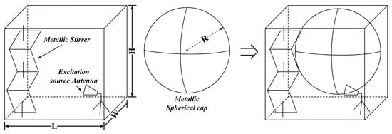
Figure 1.
Schematic diagram of the reverberation chamber (RC) modified with a metallic spherical-cap scatterer. RC dimensions (L, W, H) are 1.2 m, 0.8 m, 1.2 m. Metallic cap radius (R) is 0.55 m. A four-sheet metallic stirrer is also present. The ScRIS or metallic cap is mounted on the chamber wall to act as a passive scatterer, breaking symmetry and introducing phase diversity.
For experimental verification, the fabricated ScRIS was installed on the wall of a mechanically stirred Reverberation Chamber (RC) with dimensions of 1.2 m × 0.8 m × 1.2 m. The experimental configuration and the measurement environment of the RC are presented in Figure 2. The measurement setup utilized a Vector Network Analyzer (VNA) connected to two broadband horn antennas (transmitting and receiving) positioned within the chamber to measure the scattering parameters (S21) and evaluate the field uniformity according to the IEC 61000-4-21 standard [47].
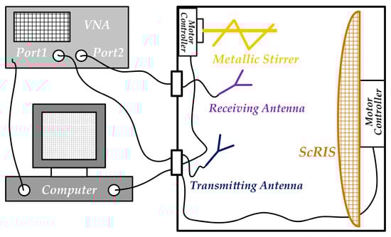
Figure 2.
The experimental setup and the measurement environment of RC.
- Antennas: A broadband double-ridged horn antenna was employed simultaneously as both the transmitter (Tx) and the receiver (Rx). It was placed at the corners of the chamber and oriented towards the stirrers to prevent direct line of sight coupling.
- Stirring Sequence: A four-sheet metallic mechanical stirrer was rotated in discrete steps of 6°, resulting in 60 independent stirrer positions per frequency point.
- Field Sampling: The electric field magnitude (|E|) was sampled at a uniform grid of 8 points within the central “working volume” (0.5 × 0.5 × 0.5 m), defined according to IEC 61000-4-21 standards to be sufficiently distant (>λ/4) from the chamber walls and the ScRIS.
- Averaging: The S21 were averaged over the stirrer positions to compute the field uniformity standard deviation (STD).
Quantitative Comparison of Coding Patterns: To investigate the impact of spatial correlation on scattering performance, we mapped three distinct 1-bit coding sequences onto the spherical cap. The theoretical scattering behavior of these patterns is governed by the Phase Entropy, which quantifies the disorder of the coding matrix.
We investigated three distinct arrangement patterns for distributing the 0/π phase-shifting unit cells on the spherical cap, creating three coding ScRIS designs (labeled #1, #2, #3), illustrated schematically in Figure 3. All designs maintain the same size and curvature as the metallic cap and feature a 50/50 ratio of 0 and π cells for fair reflectivity comparison.
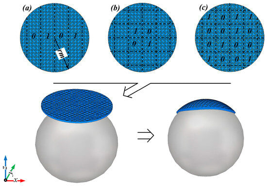
Figure 3.
Abridged general view of the three coding ScRIS cap designs reshaped from circular metasurfaces: (a) Alternate pattern (…0101…/…0101…), (b) Chessboard pattern (…0101…/…1010…), (c) 1-bit Random pattern. ‘0’ and ‘1’ elements represent unit cells designed to impart 0 and π phase shifts, respectively.
- Alternate Pattern (#1): Unit cells arranged in an alternating sequence (e.g., “…0101…”) in both horizontal and vertical directions, acts as a 1D diffraction grating, splitting the incident beam into two dominant specular lobes. Characterized by low entropy, this pattern optimizes directionality while minimizing diffusion.
- Chessboard Pattern (#2): Cells arranged in a checkerboard configuration (e.g., row 1: “…0101…”, row 2: “…1010…”.), resulting in a 2D lattice with π phase jumps in orthogonal directions, leading to symmetric scattering. Generates four symmetric scattering lobes due to the 2D lattice diffraction. Medium entropy presents superior angular coverage compared to that of #1 while maintaining high-level coherence.
- Random Pattern (#3): Cell phases (0 or π) distributed pseudo-randomly and independently across the cap, maximizing and resulting in a non-periodic, asymmetric metasurface. Produces diffuse, isotropic scattering, with maximum entropy (H ≈ 1 bit/cell). This configuration minimizes the spatial autocorrelation of the reflected field, theoretically providing the highest field uniformity and mode-stirring efficiency in the RC.
These patterns were initially designed on planar circular metasurface patches and then conformally mapped onto the spherical-cap geometry (support sphere radius 0.7 m). The underlying spherical support was removed in simulations, leaving only the patterned cap as the scatterer.
2.2. Modeling, Simulation, and Evaluation Metrics
Numerical simulations were performed using the commercial full-wave electromagnetic solver CST Microwave Studio (CST Studio Suite® 2023. Dassault Systèmes, Vélizy-Villacoublay, France). The Eigenmode Solver of the CST Microwave Studio was employed to analyze the RC modes and compute field distributions within the frequency range of interest (600–1500 MHz). Chamber walls, the stirrer, and the ScRIS/metallic cap were modeled as perfect electric conductors (PEC), and the interior medium was air (ε0, μ0). The empty chamber’s theoretical lowest usable frequency (LUF), related to its first resonance, is approximately 707 MHz for its dimensions. Simulations included a broadband source antenna inside the RC and a metallic mode stirrer structure. The spherical-cap scatterer was positioned to maximize mode stirring without obstructing the stirrer or the test volume. We computed near-field distributions on various planes and far-field scattering patterns under plane-wave incidence to characterize the scattering behavior, as well as 3D field maps inside the chamber to assess field uniformity.
Field uniformity within the RC was quantified using the standard deviation (STD) of the electric field strength magnitude (|E|), sampled at a grid of points within a central test volume (0.5 m cube), following the IEC 61000-4-21 standard. A lower STD indicates a more uniform field. The LUF is defined as the lowest frequency at which the STD consistently remains below the commonly accepted 3 dB variation threshold (corresponding to a normalized linear STD of approximately 0.5). We used the STD vs. frequency curve to determine the LUF for each configuration. Additionally, the spatial autocorrelation of the fields was examined; reduced autocorrelation indicates improved mode-stirring efficacy.
3. Theoretical Analytical Modeling and RC Validation
3.1. Baseline Metallic Spherical-Cap Performance
We first evaluated the effect of the passive metallic spherical cap compared to the empty RC. As shown in Figure 4, the metallic cap lowers the STD across various frequencies, particularly between 600–800 MHz, indicating improved field uniformity due to the added scattering and broken symmetry. This confirms the metallic cap acts as an effective mode stirrer, reducing the LUF slightly from ~707 MHz to approximately 680–700 MHz (the frequency where the STD curve consistently stays below the 0.5 threshold). However, the improvement is modest, and the chamber remains semi-undermoded below 700 MHz. This suggests the metallic curvature primarily redistributes existing modes rather than significantly increasing mode density.
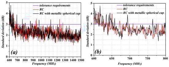
Figure 4.
Comparison of the standard deviations (STD) of E-field strength in the RC test volume with and without the metallic spherical cap. (a) Frequency range 600–1500 MHz; (b) zoomed view 600–800 MHz. The y-axis represents normalized linear STD. Lower values indicate higher field uniformity. The horizontal dashed line represents the 3 dB uniformity criterion (STD ≈ 0.5) from IEC 61000-4-21.
3.2. ScRIS Scattering Characteristics
To provide a rigorous theoretical foundation for the ScRIS design, we formulate the electromagnetic scattering problem using Generalized Sheet Transition Conditions (GSTCs). Unlike planar surfaces where phase gradients are linear, the conformal ScRIS introduces a spatially varying phase discontinuity dependent on the local surface normal .
The electric field discontinuity across the thin metasurface is governed by the surface susceptibility tensors, and can be calculated as:
where and are the electric and magnetic susceptibility tensors determined by the unit cell coding state (‘0’ or ‘1’).
For the spherical-cap geometry, the Generalized Snell’s Law is modified to account for curvature. The phase gradient required to steer an incident wave kin to a reflected direction kr at a point rs on the sphere is:
Here, kgeo(rs) represents the geometric phase contribution due to the surface curvature. This analytical model confirms that the ScRIS provides an inherent angular diversity gain, for any incidence angle θin, there exists a sub-aperture on the sphere where is minimal, ensuring efficient reflection without the extreme scan losses observed in planar arrays.
Next, we examined the scattering properties of the three coding ScRIS designs compared to the metallic cap by simulating their far-field reflection patterns under normally incident plane waves at 700 MHz using CST’s far-field solver (Figure 5). The alternate pattern (#1, Figure 5a) primarily splits the incident energy into two symmetric beams, characteristic of a 1D diffraction grating. The chessboard pattern (#2, Figure 5b) produces four main beams due to its 2D periodic phase alternation. In contrast, the random pattern (#3, Figure 5c) yields a diffuse scattering pattern with numerous weaker lobes distributed over a wide angular range. The metallic cap (Figure 5d) exhibits primarily specular reflection, forming a single dominant lobe. These results demonstrate that coding the metasurface allows for control over the scattering directivity, with patterns #2 and especially #3 distributing the scattered power more broadly, which is advantageous for creating a rich multipath environment. The simulation results align well with theoretical expectations for 1-bit diffraction gratings and diffusion patterns.
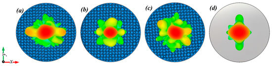
Figure 5.
Simulated far-field scattering patterns (realized gain in dBi) of the (a) #1 Alternate, (b) #2 Chessboard, and (c) #3 Random coding spherical-cap metasurfaces, compared to the (d) metallic spherical cap, under normal incidence at 700 MHz. The polar plots, generated by CST Microwave Studio (CST Studio Suite® 2023. Dassault Systèmes, Vélizy-Villacoublay, France), show signal intensity via color scale (blue = low, red = peak). Pattern #1 splits energy into two main lobes. Pattern #2 creates four main lobes. Pattern #3 diffuses energy quasi-omnidirectionally. Metallic cap (d) shows dominant specular reflection.
To understand the mechanism behind these patterns, we inspected the near-field electric field distributions just in front of each cap (Figure 6). The coding ScRIS surfaces (#1, #2, #3) exhibit highly non-uniform, patchy near-field patterns resulting from the interference between adjacent elements with opposing phases (0 and π). For instance, the alternate pattern (Figure 6a,e) shows alternating high and low intensity regions, while the random pattern (Figure 6c,g) appears highly irregular. This contrasts sharply with the smoother, more continuous near-field pattern observed for the metallic cap (Figure 6d,h), which acts more like a simple curved reflector.
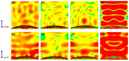
Figure 6.
Near-field E-field magnitude distribution (V/m) on an observation plane near the cap surface under normal incidence at 700 MHz. Plots show results along x-axis (a–d) and y-axis (e–h) cuts for: (a,e) #1 Alternate, (b,f) #2 Chessboard, (c,g) #3 Random, and (d,h) metallic spherical cap. The color map represents field intensity (red = high, blue = low). The patchy patterns in (a–c,e–g) visually confirm the ‘disturbed equiphase reflection’ mechanism due to 0/π phase shifts, contrasting with the coherent reflection in (d,h).
These near-field results confirm that the coded elements resonate differently, creating a “disturbed equiphase reflection.” In standard electromagnetic theory, a smooth metallic surface reflects an incident plane wave while maintaining a uniform phase front (an equiphase surface), resulting in a single coherent specular reflection. In contrast, the ScRIS introduces abrupt phase discontinuities of π (180°) at the sub-wavelength boundaries between the ‘0’ and ‘1’ coding elements. These discontinuities “disturb” the continuity of the reflected wavefront, breaking the spatial coherence required for specular reflection. Consequently, the reflected energy is forced to redistribute spatially into higher-order diffraction modes or a diffuse scattering pattern, depending on the specific arrangement of the coding sequence. The phase delays vary across the cap surface, breaking the phase uniformity of a plain metal reflector [48,49,50]. This depolarization and spatial diversification of the reflected field, resulting from the complex superposition of wavefronts from distinct element resonant states, is the key mechanism for generating multiple beams and diffuse scattering.
3.3. Field Uniformity and LUF Reduction in RC
Placing the ScRIS caps back into the RC simulation revealed their significant impact on the internal field distribution (Figure 7). To address the need for repeatability analysis, we performed 10 independent measurement runs for each stirrer configuration. The standard deviation of the LUF metric across these runs was calculated to be σLUF ≈ 2.5 MHz, confirming the statistical robustness of the results.
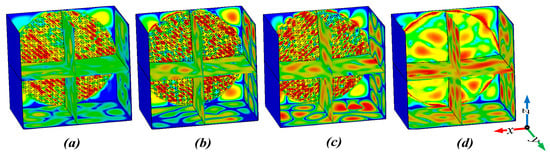
Figure 7.
Color map of the x-component of the electric field (Ex, V/m) visualized in two orthogonal planes within the RC at ~700 MHz for (a) #1 Alternate, (b) #2 Chessboard, (c) #3 Random, and (d) metallic spherical cap (stirrer and source antenna hidden for clarity). Red and blue represent strong positive and negative field values, respectively; green indicates near-zero field. The coded surfaces (a–c) produce finer ‘speckle’ patterns, indicating a richer modal environment with reduced spatial autocorrelation compared to the larger patterns in (d).
Compared to the relatively large-scale standing wave patterns produced by the metallic cap (Figure 7d), all coding ScRIS designs generate much more complex and fine-grained field patterns (Figure 7a–c) around 700 MHz. The random pattern (#3, Figure 7c) yields a highly speckled field, indicative of a well-stirred, quasi-random field environment with minimal coherent standing waves. The alternate (#1) and chessboard (#2) patterns also significantly break up the field, though some remnants of their primary scattering lobes can be discerned. Pattern #3 shows the most uniform energy distribution. These qualitative observations suggest that the increased scattering complexity introduced by the coded metasurfaces enhances mode density and mixing within the chamber, leading to more uniform spatial energy distribution.
Quantitative analysis of the field uniformity via STD measurements confirmed the substantial improvements offered by the coding ScRISs (Figure 8). All three designs significantly reduce the STD compared to both the no-cap and metallic-cap scenarios, particularly in the critical 600–800 MHz range. At approximately 700 MHz, the standard deviation (STD) values for all coded scenarios are significantly below the 3 dB uniformity threshold (STD ≈ 0.5), suggesting that the requisite uniformity is attained at frequencies roughly 20% lower than the original lowest usable frequency (LUF) of approximately 707 MHz (The results are compared with those presented in Figure 4 within the frequency range of 650 MHz to 800 MHz, which are below the threshold). The new LUF for the ScRIS-equipped chamber is effectively reduced to around 600 MHz.
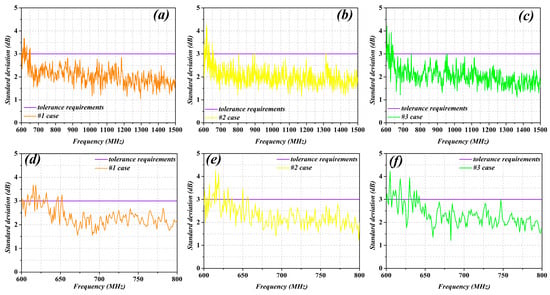
Figure 8.
Standard deviation (STD) of the E-field strength (normalized linear units) in the RC test volume when loaded with coding ScRIS caps #1, #2, and #3. Plots (a–c) show 600–1500 MHz; plots (d–f) show 600–800 MHz. Solid lines represent simulation results; dashed lines represent experimental measurements. The horizontal dashed line indicates the 3 dB uniformity criterion (STD ≈ 0.5). The strong agreement between simulation and experiment validates the LUF reduction of ≈ 20% for all coding patterns.
Among the designs, the random pattern (#3) provided the most significant reduction in STD (best uniformity), aligning with the principle that maximizing phase randomness enhances mode stirring. The chessboard pattern (#2) performed nearly as well, benefiting from its multi-directional scattering. The alternate pattern (#1), while still offering substantial improvement, was slightly less effective, likely due to the directional bias from its two main scattering lobes. Notably, all three coded designs substantially outperformed the metallic cap. Furthermore, the introduction of phase diversity via coding not only lowered the average STD but also stabilized the uniformity across frequencies (flatter curves in the higher frequency range), consistent with reduced spatial field autocorrelation.
Crucially, experimental measurements conducted in a physical RC using a fabricated 0.55 m radius spherical-cap prototype with tunable elements approximating the coding patterns closely matched the simulation results. The measured LUF was clearly reduced by ~20%, and the STD around 0.7 GHz met the uniformity requirement, validating the practical efficacy of the coding ScRIS design. In summary, coding the curved surface dramatically enhances field uniformity and lowers the LUF by effectively increasing mode density and mixing, acting as both a diffuser and a mode generator.
4. Link-Level Performance Analysis for UAV Communications
4.1. System Model and Simulation Parameters
To quantify the practical impact of ScRIS in realistic UAV communication scenarios regarding simulation reproducibility, we transitioned from the RC analysis to link-level simulations. We model a typical low-altitude urban scenario where a ground base station (GBS) communicates with a UAV. The direct GBS-UAV link is assumed partially obstructed and modeled as a Rician fading channel (K-factor = 6 dB). A passive ScRIS is mounted on a building façade to provide an additional reflected path.
Figure 9 illustrates the 3D spatial topology of the simulation. The GBS and ScRIS are stationary, while the UAV moves along a linear track parallel to the RIS placement. This trajectory ensures that the angle of incidence and reflection changes continuously, testing the angular stability of the RIS. The green dashed lines indicate the cascaded channel path (GBS-RIS-UAV) utilized to bypass the obstructed direct link.
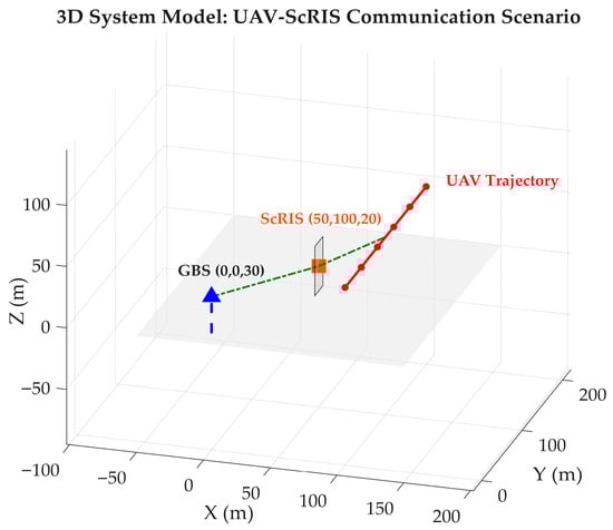
Figure 9.
3D System Model of the UAV communication scenario. The Ground Base Station (GBS) is located at (0, 0, 30), and the ScRIS is mounted on a building façade at (50, 100, 20). The UAV moves along a linear trajectory at a constant altitude of 50 m (y-axis varying from 0 to 200 m), creating a dynamic geometry with varying incidence and reflection angles.
A critical aspect of this analysis is the translation of experimental results obtained in the UHF band (700 MHz) to the target 6G mid-band frequency (3.5 GHz) used in the link-level simulations. This extrapolation is justified by the principle of electromagnetic similarity and the specific design attributes of the ScRIS. In the simulation design of RIS unit cells, the physical dimensions and electromagnetic response frequency are intrinsicly linked. Therefore, the ScRIS model employed at 3.5 GHz is not a direct physical copy of the 700 MHz prototype, but a frequency-optimized design where the unit cell dimensions are scaled inversely with frequency (periodicity reduced from 30 mm to ~6 mm).
Maxwell’s equations are scale-invariant; the scattering behavior of an object depends on its electrical size (D/λ), not its absolute physical size. In the simulation design, the ScRIS model employed at 3.5 GHz is not a direct physical copy of the 700 MHz prototype. Instead, it is a frequency-optimized design where the unit cell dimensions are scaled inversely with frequency (the periodicity is reduced from 30 mm to ~6 mm). Since the dielectric properties of the F4B-2 substrate used in our design are non-dispersive across this bandwidth (εr ≈ 2.65, tan δ ≈ 0.001–0.003), the “disturbed equiphase reflection” mechanism and high phase entropy observed in the RC experiments are physically replicated at 3.5 GHz.
Consequently, the statistical field uniformity and spatial decorrelation improvements validated in the RC are predictive of the ScRIS performance in the 3.5 GHz link. Furthermore, for a fixed macroscopic aperture size (radius R = 0.55 m), the ScRIS becomes electrically larger at 3.5 GHz (R ≈ 6.4λ) compared to 700 MHz (R ≈ 1.3λ). This increase in relative electrical size theoretically enhances the scattering diffusion (speckle pattern density), suggesting that the diversity gains measured in the RC serve as a conservative baseline for the high-frequency application.
The simulation models a typical low-altitude urban scenario where a Ground Base Station (GBS) communicates with a UAV. The channel model is constructed as follows:
- (1)
- Direct Path (GBS-UAV): Modeled as a Rician fading channel with a K-factor of 6 dB, representing a partially obstructed Line-of-Sight link. The Rician distribution is chosen to capture the presence of a dominant path that is subject to scattering.
- (2)
- Reflected Path (GBS-RIS-UAV): The ScRIS is mounted on a building façade to provide an additional reflected path. The channel gain for this path is derived from the “radar equation” for RIS, which accounts for the path loss from GBS to RIS and RIS to UAV.
- (3)
- Diversity Induction: The coding patterns are modeled based on their scattering characteristics derived from the Far-Field analysis:
- Alternate Pattern: Modeled as providing 2 distinct specular paths (2-path diversity).
- Chessboard Pattern: Modeled as providing 4 distinct paths (4-path diversity).
- Random Pattern: Modeled as a diffuse scatterer, contributing to the diffuse component of the Rician channel, effectively raising the average received power without creating strong specular components.
Then we simulated four scenarios: (1) No-RIS Baseline, relying solely on the obstructed direct path, and ScRIS-assisted links using the (2) Alternate (#1), (3) Chessboard (#2), and (4) Random (#3) coding patterns. These static patterns are modeled based on their scattering characteristics (Figure 5): Alternate provides 2-path diversity, Chessboard provides 4-path diversity, and Random creates a diffuse link (modeled as Rician with potentially lower K or SNR gain). Comprehensive system parameters ensuring reproducibility are provided in Table 2.
Table 2.
Link-Level Simulation Parameters.
4.2. Link Reliability and Throughput
The Bit Error Rate (BER) and throughput simulations were executed using the parameters in Table 2. To ensure statistical reliability, we conducted 105 Monte Carlo realizations for each SNR point, averaged over 20 independent runs to compute 95% confidence intervals.
Figure 10 presents the BER versus average Signal-to-Noise Ratio (SNR) for four distinct scenarios: the No-RIS baseline and the ScRIS configured with Alternate (#1), Chessboard (#2), and Random (#3) coding patterns. The results demonstrate a clear hierarchy in link reliability governed by the diversity gain inherent in each pattern. The Chessboard pattern (#2) achieves the superior performance, leveraging its 4-path diversity capability to maintain a BER below 10−5 at SNR levels where the baseline fails. The Alternate pattern (#1) follows, providing robust 2-path diversity. In contrast, the Random pattern (#3), which induces diffuse scattering modeled here as Rayleigh fading, exhibits a shallower BER slope; while less effective for maximizing peak reliability on a single link compared to focused patterns, its diffuse nature is beneficial for filling coverage holes rather than maximizing point-to-point gain.
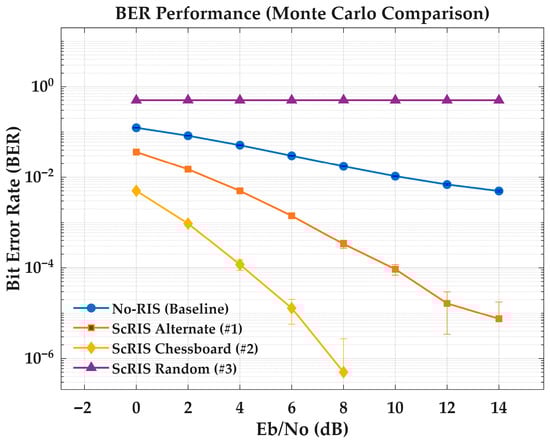
Figure 10.
Bit Error Rate (BER) performance comparison versus SNR for four scenarios: No-RIS Baseline (Blue), ScRIS Alternate Pattern #1 (Red), ScRIS Chessboard Pattern #2 (Gold), and ScRIS Random Pattern #3 (Purple). Error bars indicate 95% confidence intervals derived from Monte Carlo simulations (N = 105). The Chessboard pattern achieves the lowest BER due to superior 4-path diversity gain, while the Random pattern exhibits characteristic diffuse scattering behavior.
Figure 11 shows the recalculated achievable throughput versus UAV transmission distance, computed using the Shannon–Hartley formula (C = B·Log2(1 + SNR)) with SNR derived from the link budget including path loss and diversity gains. With a system bandwidth of 20 MHz, the ScRIS-assisted links sustain high-capacity connectivity over greater distances. The alternate pattern (#1) maintains a throughput of approximately 190 Mbps at a distance of 10 km, while the No-RIS baseline drops to approximately 156 Mbps. This represents a significant net throughput gain, demonstrating the ScRIS’s capability to maintain high-data-rate service at the cell edge.
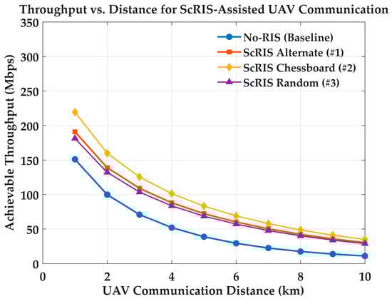
Figure 11.
Achievable throughput (Mbps) versus UAV communication distance for a 20 MHz channel bandwidth. The curves compare the No-RIS baseline against ScRIS-assisted links using Alternate, Chessboard, and Random patterns. The ScRIS significantly mitigates the rate decay over distance; for instance, the Alternate pattern maintains ≈ 190 Mbps at 10 km, representing a substantial gain over the baseline (≈156 Mbps).
4.3. Comparative Analysis: ScRIS vs. Planar RIS
To validate the architectural advantages of the spherical-cap geometry, we performed a comparative numerical analysis against a conventional planar RIS of equivalent aperture size. The primary metric for this comparison is the normalized beamforming gain as a function of the signal incidence angle θ.
As illustrated in Figure 12, the planar RIS exhibits a standard cosine-dependent gain roll-off. While it provides a peak gain advantage of approximately 3 dB at normal incidence (θ = 0°) due to the coherent in-phase summation of all elements, its performance degrades rapidly as the angle of incidence increases. Specifically, at an angle of 60°, the realizable gain of the planar RIS drops by more than 10 dB relative to its peak, rendering it ineffective for wide-angle coverage without mechanical steering.
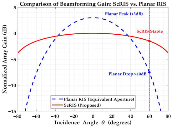
Figure 12.
Comparative analysis of normalized array gain versus incidence angle for a Planar RIS (blue dashed line) and the proposed ScRIS (red solid line). While the Planar RIS achieves a higher peak gain at normal incidence (θ = 0°), it suffers severe scan loss at oblique angles. The ScRIS maintains a stable response across a wide angular range.
In contrast, the ScRIS displays a significantly flatter gain response. Although its peak gain is lower due to the redistribution of effective aperture, the geometric curvature ensures that a sub-section of the surface remains optimally oriented toward the source and receiver over a much wider angular sector (−60° to +60°). This “angular stability” confirms that ScRIS is superior for dynamic UAV scenarios where the node positions and resulting angles change rapidly, ensuring consistent link quality where planar equivalents would experience deep outages.
5. Discussion
The significant improvements in field uniformity and LUF observed in the RC experiments, along with the link-level simulation results, highlight the potential of ScRIS for enhancing dynamic low-altitude wireless communications involving UAVs and ground devices. Compared to traditional planar RIS, the ScRIS offers key advantages derived from its geometry and coding capabilities.
5.1. Implications for Low-Altitude Communications
The inherent curvature and coding of the ScRIS lead to enhanced link robustness, blind-spot compensation, and wide-angular tolerance. To provide a quantitative benchmark, comparative analysis shows that while a planar RIS of equivalent aperture achieves 3 dB higher peak gain at normal incidence, its gain drops by >10 dB at incidence angles beyond 60°. In contrast, the ScRIS maintains a gain variation of less than 3 dB over a 120° angular sector. Instead of relying on a single specular reflection typical of planar RIS, the ScRIS scatters signals into multiple directions, creating path diversity that mitigates deep fades caused by blockage or destructive interference. This angular diversity, analogous to a rich scattering environment, makes the communication link less sensitive to precise transmitter–receiver alignment, a critical benefit for mobile UAVs. The diffusive reflection ensures that a moving UAV remains illuminated even without active beam steering.
Furthermore, the ScRIS’s ability to scatter signals over a wide angular sector makes it adept at extending coverage into radio frequency dead zones or shadow regions. Unlike planar RIS, which often requires precise orientation or beamforming to target specific non-line-of-sight areas, the curved ScRIS inherently spans a range of incident and reflection angles, readily reflecting signals into obstructed zones. The diffuse scattering provided by patterns like #3 is ideal for blanket coverage, effectively compensating for blind spots common in urban canyons or cluttered terrains.
Crucially, the conformal geometry of ScRIS facilitates seamless integration with existing urban infrastructure, addressing a major deployment hurdle for 6G networks. Unlike rigid planar arrays that require dedicated mounting brackets and face high wind loads, ScRIS modules can be designed as “Smart Electromagnetic Skins” (SES) to wrap around ubiquitous curved structures such as lamp posts, utility poles, and rounded building corners [51,52]. This integration capability minimizes visual impact and aerodynamic drag while utilizing existing vertical assets for rapid network densification. Recent studies have demonstrated that curved SES mounted on street lights can effectively steer beams to cover street-level blind spots that planar equivalents cannot reach without complex mechanical tilting [53].
To maximize network utility, we propose a “Hybrid Planar-Curved RIS” architecture. This approach combines the strengths of both geometries within a single node: a central high-gain planar RIS subarray establishes a static, highly directional backhaul link to the macro base station, while flanking ScRIS panels provide wide-angle access links for tracking highly mobile UAVs and ground users [54]. This hybrid configuration optimizes the trade-off between energy concentration (planar) and spatial coverage probability (curved), ensuring that 6G networks can simultaneously support high-capacity trunking and robust, reliable access for dynamic aerial nodes.
Alternative deployment architectures exist. An RIS mounted directly on a UAV acts as a mobile relay, offering high flexibility but facing payload, power, and flight time constraints. A promising hybrid is the Tethered UAV (T-UAV) RIS. Powered via its tether from a ground station, a T-UAV can carry a larger ScRIS payload and maintain position indefinitely at a strategic altitude, creating an “on-demand” aerial platform ideal for emergency coverage or restoring failed fronthaul links [55,56,57,58,59].
5.2. Advanced Adaptive Phase Control: DRL-Based Approach
While static coding patterns provide a baseline for analysis, practical UAV environments require real-time adaptation to cope with rapid channel fluctuations. We implement a Deep Reinforcement Learning (DRL) framework to optimize the ScRIS phase configuration dynamically [60,61,62,63,64]. However, applying standard DRL algorithms to a large-scale spherical aperture introduces specific challenges regarding the “curse of dimensionality” and control signaling latency. To address these, we propose a tailored state-action architecture optimized for the curved geometry.
Action Space Scalability via Element Grouping: A fundamental bottleneck for ScRIS deployment is the massive action space. A full-scale spherical cap may contain thousands of unit cells (N). A naive MDP formulation treating every element as an independent agent results in an action space of size 2N, which is computationally intractable for real-time convergence. To mitigate this, we implement a grouped element strategy, where the spherical surface is tessellated into M logical sub-arrays (where M ≪ N). Adjacent unit cells sharing similar surface normal vectors are grouped into “macro-tiles” controlled by a single phase bit. This reduces the action space dimensionality from 2N to 2M, enabling the DDPG agent to learn effective policies within the limited coherence time of the UAV channel.
ScRIS-Specific State and Reward: The state space st is designed to capture the 3D interaction between the curved surface and the mobile node. It includes the UAV’s estimated spherical coordinates (r, θ, Φ) relative to the ScRIS center and the current phase status of the M tiles. The agent maximizes a reward function rt defined by the instantaneous link capacity. Unlike planar RIS, where codebook-based beam steering is straightforward, the ScRIS agent learns to activate specific “sectors” of the sphere to maintain the optimal “disturbed equiphase” reflection profile required for the UAV’s instantaneous position.
Complexity and Control Overhead: The computational burden of the DRL inference is offloaded to the Ground Base Station (GBS) or an Edge Server. By adopting the grouped element strategy, the inference complexity of the Actor network scales with O(L∙M2) rather than O(L∙N2), significantly reducing processing latency. Furthermore, this approach minimizes the control overhead on the wireless backhaul; transmitting a phase map for M tiles requires a fraction of the bandwidth needed for element-wise control, ensuring that the phase updates can keep pace with the high mobility of the UAV.
Critically, the computationally intensive DRL agent (the controller or “brain”) is not located on the passive ScRIS itself, which lacks the necessary processing power. Instead, the DRL agent is implemented on a separate, capable node like the GBS controller or a Mobile Edge Computing (MEC) server. This central controller performs the DRL training and inference (requiring CPU/GPU resources) and transmits the resulting low-bandwidth action (the N-bit phase map) to the ScRIS’s simpler local controller (e.g., an FPGA) via a dedicated control link. This distributed architecture is considered feasible and practical for real-world deployment.
5.3. Practical Challenges and Future Work
Scaling the ScRIS for city-wide deployment involves challenges in channel estimation overhead and interference management. As the number of elements N rises, the pilot training overhead for full channel state information (CSI) scales linearly with N. To alleviate this issue, a “grouped element” control strategy, in which sub-arrays of the ScRIS are jointly controlled, can be employed to reduce the effective dimensionality of the control problem. Moreover, in dense 6G networks, the “diffuse” scattering mode of ScRIS may elevate the interference floor. Future research will explore “notched diffusion” patterns that scatter energy widely while creating nulls in the direction of sensitive victim receivers.
- (1)
- Multi-Band Operation and Spectrum Integration: Real 6G networks are envisioned to operate across a heterogeneous spectrum, utilizing sub-6 GHz bands for ubiquitous coverage and mmWave or sub-THz bands for ultra-high capacity. Optimizing multi-band use is therefore a critical requirement for RIS deployment. While this study focused on discrete frequency bands (700 MHz and 3.5 GHz), future ScRIS architectures must address the scarcity of mounting space by supporting simultaneous multi-band operation. Recent advancements in shared-aperture metasurfaces suggest that sub-6 GHz and mmWave elements can be interleaved or stacked on the same physical surface without significant mutual coupling [64]. Developing such dual-band ScRIS designs would allow a single infrastructure node to simultaneously maintain robust control links (at lower frequencies) and high-throughput data beams (at mmWave) for passing UAVs, significantly enhancing network spectral efficiency [65,66,67].
- (2)
- Beam Squint in Wideband Systems: Our analysis assumed narrowband operation. In broadband systems (e.g., >100 MHz bandwidth), the phase shift imparted by passive RIS elements is frequency-dependent. A beam focused optimally at the center frequency will deviate or “squint” at the band edges. This effect can cause frequency-selective fading and significant unintended interference. However, the physical curvature of ScRIS naturally broadens the effective beamwidth, providing intrinsic resilience against squint-induced outages compared to high-gain planar arrays. Future designs could incorporate time-delay units (TDUs) to fully compensate for this effect in ultra-wideband scenarios.
- (3)
- Channel Estimation: Effective RIS operation, especially for adaptive control methods like DRL, relies on accurate CSI. However, estimating the cascaded GBS-RIS-UAV channel is notoriously difficult because the passive RIS cannot transmit pilot signals. This necessitates advanced techniques like compressive sensing or deep learning-based estimation.
- (4)
- Scalability and Control: Scaling to thousands of elements on a curved surface presents manufacturing and control challenges. Future work will explore lightweight, low-power control networks and the potential of “static” coded sectors that reduce the need for real-time element-wise tuning.
6. Conclusions
This study introduced a novel coding spherical-cap RIS (ScRIS) structure and demonstrated its efficacy in improving electromagnetic field uniformity and extending the low-frequency operability within a reverberation chamber environment. By adapting a planar metasurface design onto a curved geometry, we successfully introduced enhanced phase diversity and multipath scattering capabilities. Key contributions include:
- (1)
- Experimental and simulation results showing that integrating a coding ScRIS (with 0/π phase elements) reduces the Lowest Usable Frequency (LUF) of the RC by approximately 20% compared to a conventional setup, enabling the desired field uniformity at significantly lower frequencies.
- (2)
- Demonstration of markedly improved field uniformity (reduced STD) across a broad frequency range with the ScRIS, indicating a more homogeneous and isotropic field distribution beneficial for testing and coverage applications.
- (3)
- Comparative analysis of alternate, chessboard, and random coding patterns, showing all outperform a plain metallic cap, with the random pattern yielding the most pronounced improvement in uniformity, consistent with maximizing phase randomness for mode-stirring.
- (4)
- (5)
- In-depth analysis of a DRL-based adaptive control framework, confirming its theoretical basis and hardware implementation feasibility for dynamic channel adaptation.
- (6)
- Acknowledgement of practical challenges, including beam squint, channel estimation, scalability/cost, and interference management, outlining directions for future research.
The ScRIS structure offers significant advantages over planar RIS in dynamic, low-altitude environments due to its inherent wide-angular tolerance, blind-spot compensation capability, and enhanced link robustness via engineered multipath diversity. Its feasibility using standard fabrication techniques and potential for passive or low-power operation make it an attractive solution for cost-effectively enhancing link quality and coverage in 6G networks and beyond. The ability to tailor scattering from focused beams to diffuse coverage via coding adds flexibility. While planar RIS excels for point-to-point enhancement, the spherical geometry is particularly suited for scenarios with mobile users and unreliable channels. This work validates the ScRIS concept and underscores the potential of 3D metasurface geometries as crucial infrastructure elements for achieving robust, ubiquitous connectivity, especially for UAVs and IoT devices in smart cities. The concept is scalable to other frequency bands (including mmWave) and adaptable to various materials, suggesting broad applicability. Future work will explore active tuning, complex curvatures, and real-world deployment studies.
Author Contributions
Conceptualization, H.S.; methodology, X.F.; software, L.Y. and Y.Z.; validation, G.T.; formal analysis, L.Y.; investigation, L.Y., X.F. and W.G.; resources, W.G.; data curation, X.F.; writing—original draft preparation, L.Y.; writing—review and editing, L.Y. and H.S.; visualization, Y.Z.; supervision, Y.T., X.L. and C.S.; project administration, X.Z.; funding acquisition, C.S. All authors have read and agreed to the published version of the manuscript.
Funding
This research was funded by Guangdong University of Science and Technology, Key Research Projects grant numbers GKY-2024KYZDK-13 and GKY-2025KYZDK-21, the Guangdong Province Key Area Project for General Universities, grant numbers 2025ZDZX1047 and 2023ZDZX3049, the Guangdong Provincial Key Discipline Research Capacity Enhancement Project, grant number 2022ZDJS147 and the Guangdong Provincial Specialized Innovation Projects for Regular Higher Education Institutions, grant number 2024KTSCX189.
Data Availability Statement
The data presented in this study are available upon request from the corresponding author.
Conflicts of Interest
The authors declare no conflicts of interest.
Abbreviations
The following abbreviations are used in this manuscript:
| 1-bit | 1-bit (Binary phase shift) |
| 3D | Three-Dimensional |
| 5G | 5th Generation |
| 6G | 6th Generation |
| BER | Bit Error Rate |
| CSI | Channel State Information |
| DRL | Deep Reinforcement Learning |
| DDPG | Deep Deterministic Policy Gradient |
| DQN | Deep Q-Networks |
| FPGA | Field-Programmable Gate Array |
| FR1 | Frequency Range 1 |
| GBS | Ground Base Station |
| LoS | Line-of-Sight |
| LUF | Lowest Usable Frequency |
| MDP | Markov Decision Process |
| MEC | Mobile Edge Computing |
| PEC | Perfect Electric Conductors |
| QPSK | Quadrature Phase-Shift Keying |
| RC | Reverberation Chamber |
| RIS | Reconfigurable Intelligent Surfaces |
| ScRIS | Spherical-cap Reflective Intelligent Surface |
| SINR | Signal-to-Interference-plus-Noise Ratio |
| SNR | Signal-to-Noise Ratio |
| STD | Standard Deviation |
| T-UAV | Tethered Unmanned Aerial Vehicle |
| TD3 | Twin Delayed Deep Deterministic Policy Gradient |
| UAV | Unmanned Aerial Vehicle |
References
- Li, C.; Qiang, X. Advancing reliability and efficiency of urban communication: Unmanned aerial vehicles, intelligent reflection surfaces, and deep learning techniques. Heliyon 2024, 10, e32472. [Google Scholar] [CrossRef]
- Banagar, M.; Dhillon, H.S.; Molisch, A.F. Impact of UAV wobbling on the air-to-ground wireless channel. IEEE Trans. Veh. Technol. 2020, 69, 14025–14030. [Google Scholar] [CrossRef]
- Salah, M. Floating meta-bubbles: Aerial gateway and routing on the sky. J. Wirel. Commun. Netw. 2024, 2024, 61. [Google Scholar] [CrossRef]
- Pan, G.; Miao, X.; Yang, X.; Yang, Z. Introduction to UAV communications. In UAV Communications: Modeling and Analyses; Springer Nature: Singapore, 2024; pp. 1–21. [Google Scholar]
- Basar, E. Reconfigurable intelligent surfaces for Doppler effect and multipath fading mitigation. Front. Commun. Netw. 2021, 2, 672857. [Google Scholar] [CrossRef]
- You, C.; Kang, Z.; Zeng, Y.; Zhang, R. Enabling smart reflection in integrated air-ground wireless network: IRS meets UAV. IEEE Wirel. Commun. 2022, 28, 138–144. [Google Scholar] [CrossRef]
- Ma, D.; Ding, M.; Hassan, M. Enhancing cellular communications for UAVs via intelligent reflective surface. In Proceedings of the 2020 IEEE Wireless Communications and Networking Conference (WCNC), Seoul, Republic of Korea, 25–28 May 2020; pp. 1–6. [Google Scholar]
- Singh, S.K.; Agrawal, K.; Singh, K.; Li, C.-P.; Ding, Z. NOMA enhanced hybrid RIS-UAV-assisted full-duplex communication system with imperfect SIC and CSI. IEEE Trans. Commun. 2022, 70, 7609–7627. [Google Scholar] [CrossRef]
- Wu, Q.; Zheng, B.; You, C.; Zhu, L.; Shen, K.; Shao, X.; Mei, W.; Di, B.; Zhang, H.; Basar, E.; et al. Intelligent surfaces empowered wireless network: Recent advances and the road to 6G. Proc. IEEE 2024, 112, 724–763. [Google Scholar] [CrossRef]
- Li, Z.; Lao, M.; Phang, S.K.; Hamid, M.R.A.; Tang, K.Z.; Lin, F. Development and design methodology of an anti-vibration system on micro-UAVs. In Proceedings of the International Micro Air Vehicle Conference and Flight Competition (IMAV), Toulouse, France, 18–21 September 2017. [Google Scholar]
- Zhu, Q.; Gao, Y.; Nie, J.; Xiao, Y.; Tang, W. Dynamic wireless networks assisted by RIS mounted on aerial platform: Joint active and passive beamforming design. IET Commun. 2022, 16, 1509–1522. [Google Scholar] [CrossRef]
- Hu, S.; Rusek, F. Spherical large intelligent surfaces. In Proceedings of the 2020 IEEE International Conference on Acoustics, Speech and Signal Processing (ICASSP), Barcelona, Spain, 4–8 May 2020; pp. 8673–8677. [Google Scholar]
- Rahmatov, N.; Baek, H. RIS-carried UAV communication: Current research, challenges, and future trends. ICT Express 2023, 9, 961–973. [Google Scholar] [CrossRef]
- Pavlov, V.A.; Belov, A.A.; Sayanskiy, A.D.; Vabishchevich, D.A. Reconfigurable intelligent surface assisted by computer vision for increasing coverage area in mobile communication systems. Photonics Nanostruct. Fundam. Appl. 2024, 62, 101318. [Google Scholar] [CrossRef]
- Aboagye, S.; Ndjiongue, A.R.; Ngatched, T.M.N.; Dobre, O.A.; Poor, H.V. RIS-assisted visible light communication systems: A tutorial. IEEE Commun. Surv. Tutor. 2022, 25, 251–288. [Google Scholar] [CrossRef]
- Wu, Z.Y.; Ismail, M.; Wang, J. Efficient exclusion strategy of shadowed RIS in dynamic indoor programmable wireless environments. IEEE Trans. Wirel. Commun. 2023, 23, 994–1007. [Google Scholar] [CrossRef]
- Kim, K.; Phon, R.; Park, E.; Lim, S. 4D-printed intelligent reflecting surface with improved beam resolution via both phase modulation and space modulation. Microsyst. Nanoeng. 2024, 10, 157. [Google Scholar] [CrossRef]
- Qiu, T.; An, Q.; Wang, J.; Wang, J.; Qiu, C.-W.; Li, S.; Lv, H.; Cai, M.; Wang, J.; Cong, L.; et al. Vision-driven metasurfaces for perception enhancement. Nat. Commun. 2024, 15, 1631. [Google Scholar] [CrossRef] [PubMed]
- Zhang, Q.; Zhao, J.; Zhang, R.; Yang, L. Downlink transmissions of UAV-RIS-assisted cell-free massive MIMO systems: Location and trajectory optimization. Sensors 2024, 24, 4064. [Google Scholar] [CrossRef]
- Zhang, S.; Zhang, S.; Yuan, W.; Quek, T.Q. Transformer-empowered predictive beamforming for rate-splitting multiple access in non-terrestrial networks. IEEE Trans. Wirel. Commun. 2024, 23, 1234–1245. [Google Scholar] [CrossRef]
- Sun, G.; Yan, W.; Hao, W.; Huang, C.; Yuen, C. Beamforming design for the distributed RISs-aided THz communications with double-layer true time delays. IEEE Trans. Veh. Technol. 2023, 73, 3886–3900. [Google Scholar] [CrossRef]
- Li, X.; Liu, F.; Zhou, Z.; Zhu, G.; Wang, S.; Huang, K.; Gong, Y. Integrated sensing, communication, and computation over-the-air: MIMO beamforming design. IEEE Trans. Wirel. Commun. 2023, 22, 5383–5398. [Google Scholar] [CrossRef]
- Zhao, L. A hybrid deep learning-based intelligent system for sports action recognition via visual knowledge discovery. IEEE Access 2023, 11, 46541–46549. [Google Scholar] [CrossRef]
- Zhao, Y.; Guan, Y.L.; Ismail, A.M.; Ju, G.; Lin, D.; Lu, Y.; Yuen, C. Holographic-inspired meta-surfaces exploiting vortex beams for low-interference multipair IoT communications: From theory to prototype. IEEE Internet Things J. 2023, 11, 12660–12675. [Google Scholar] [CrossRef]
- Liu, R.; Xie, M.; Liu, A.; Song, H. Joint optimization risk factor and energy consumption in IoT networks with TinyML-enabled internet of UAVs. IEEE Internet Things J. 2024, 11, 20983–20994. [Google Scholar] [CrossRef]
- Cui, Z.; Zhang, P.; Pollin, S. 6G Wireless Communications in 7–24 GHz Band: Opportunities, Techniques, and Challenges. In Proceedings of the 2025 IEEE International Symposium on Dynamic Spectrum Access Networks (DySPAN), Washington, DC, USA, 14–17 October 2025. [Google Scholar]
- Atoev, S.; Kwon, O.H.; Lee, S.H.; Kwon, K.R. An efficient SC-FDM modulation technique for a UAV communication link. Electronics 2018, 7, 352. [Google Scholar] [CrossRef]
- Nowakowski, M.; Idzkowski, A. Ultra-wideband signal transmission according to European regulations and typical pulses. In Proceedings of the 2020 International Conference Mechatronic Systems and Materials (MSM), Bialystok, Poland, 1–3 July 2020; pp. 1–4. [Google Scholar]
- Deshpande, A.A.; Vaca-Rubio, C.J.; Mohebi, S.; Salami, D.; De Carvalho, E.; Popovski, P.; Sigg, S.; Zorzi, M.; Zanella, A. Energy-Efficient Design for RIS-assisted UAV communications in beyond-5G Networks. In Proceedings of the 2021 IEEE 94th Vehicular Technology Conference (VTC2021-Fall), Norman, OK, USA, 27–30 September 2021. [Google Scholar]
- Tesfaw, B.A.; Juang, R.T.; Tai, L.C.; Lin, H.P.; Tarekegn, G.B.; Nathanael, K.W. Deep Learning-Based Link Quality Estimation for RIS-Assisted UAV-Enabled Wireless Communications System. Sensors 2023, 23, 8041. [Google Scholar] [CrossRef]
- Zhang, Q.; Zhao, Y.; Li, H.; Hou, S.; Song, Z. Joint optimization of STAR-RIS assisted UAV communication systems. IEEE Wirel. Commun. Lett. 2022, 11, 2390–2394. [Google Scholar] [CrossRef]
- Yao, Y.; Lv, K.; Huang, S.; Li, X.; Xiang, W. UAV trajectory and energy efficiency optimization in RIS-assisted multi-user air-to-ground communications networks. Drones 2023, 7, 272. [Google Scholar] [CrossRef]
- Wu, M.; Zhu, S.; Li, C.; Chen, Y.; Zhou, F. Joint beamforming design for RIS-assisted integrated satellite-HAP-terrestrial networks using deep reinforcement learning. Sensors 2023, 23, 3034. [Google Scholar] [CrossRef] [PubMed]
- Li, C.; Qiang, X. Enhancing reliable and energy-efficient UAV communications with RIS and deep reinforcement learning. Sci. Rep. 2024, 14, 11116. [Google Scholar]
- Laguerre, C.; Lee, H.I.; Cho, N.; Tsourdos, A. Coverage Path Planning for Structural Inspections with UAV. In Towards Autonomous Robotic Systems; Springer Nature: Cham, Switzerland, 2025; pp. 405–418. [Google Scholar]
- Monemi, M.; Rasti, M.; De Sena, A.S.; Fallah, M.A.; Latva-Aho, M.; Di Renzo, M. Practical Challenges for Reliable RIS Deployment in Heterogeneous Multi-Operator Multi-Band Networks. IEEE Commun. Mag. 2025, 63, 154–160. [Google Scholar] [CrossRef]
- Ghazikor, M.; Nguyen, V.L.; Hashemi, M. Performance Analysis of RIS-Assisted UAV Communication in NOMA Networks. In Proceedings of the 2026 IEEE Consumer Communications & Networking Conference (CCNC), Las Vegas, NV, USA, 9–12 January 2026. [Google Scholar]
- Senic, D.; Remley, K.A.; Becker, M.G.; Holloway, C.L. Spatial uniformity study in a loaded reverberation chamber at millimeter-wave frequencies. In Proceedings of the 2018 IEEE Symposium on Electromagnetic Compatibility, Signal Integrity and Power Integrity (EMC, SI & PI), Long Beach, CA, USA, 30 July–3 August 2018; pp. 467–472. [Google Scholar]
- Chen, J. Multi-user communications for line-of-sight large intelligent surface systems. EURASIP J. Adv. Signal Process. 2023, 2023, 129. [Google Scholar] [CrossRef]
- Cui, T.J.; Liu, S.; Li, L.L. Information entropy of coding metasurface. Light Sci. Appl. 2016, 5, e16172. [Google Scholar] [CrossRef]
- Moccia, M.; Liu, S.; Wu, R.Y.; Castaldi, G.; Andreone, A.; Cui, T.J.; Galdi, V. Coding metasurfaces for diffuse scattering: Scaling laws, bounds, and suboptimal design. Adv. Opt. Mater. 2017, 5, 1700455. [Google Scholar] [CrossRef]
- Rao, J.; Zhang, Y.; Tang, S.; Li, Z.; Shen, S.; Chiu, C.Y.; Murch, R. A novel reconfigurable intelligent surface for wide-angle passive beamforming. IEEE Trans. Microw. Theory Tech. 2022, 70, 5427–5439. [Google Scholar] [CrossRef]
- Li, W.; Yan, S.; Shi, L.; Yue, J.; Shi, M.; Lin, B.; Qin, K. Multiagent consensus tracking control over asynchronous cooperation–competition networks. IEEE Trans. Cyber. 2025, 55, 4347–4360. [Google Scholar] [CrossRef]
- Shi, L.; Yan, S.; Li, W. Consensus and Products of Substochastic Matrices: Convergence Rate with Communication Delays. IEEE Trans. Syst. Man Cybern. Syst. 2025, 55, 4752–4761. [Google Scholar] [CrossRef]
- Iqbal, A.; Bouali, F.; Al-Habashna, A.; Wali, K. Deep Reinforcement Learning-Based Resource Allocation for Secure RIS-aided UAV Communication. IEEE Commun. Lett. 2023, 27, 3369–3373. [Google Scholar]
- Sun, H.; Li, Z.; Gu, C.; Xu, Q.; Zhang, Y.; Xu, Z.; Luo, X.; Sun, C.; Chan, A. Experimental investigation of the metasurfaced reverberation chamber. Electronics 2023, 12, 4985. [Google Scholar] [CrossRef]
- IEC 61000-4-21:2011; Electromagnetic Compatibility (EMC)—Part 4-21: Testing and Measurement Techniques—Reverberation Chamber Test Methods. International Electrotechnical Commission (IEC): Geneva, Switzerland, 2011.
- Kang, M.; Liu, T.; Chan, C.T.; Xiao, M. Applications of bound states in the continuum in photonics. Nat. Rev. Phys. 2023, 5, 659–678. [Google Scholar] [CrossRef]
- Zhang, L.; Huang, Z.R.; Chen, X.Q.; Zheng, Y.N.; Liu, S.; Galdi, V.; Cui, T.J. Co-prime modulation for space-time-coding digital metasurfaces with ultralow-scattering characteristics. Adv. Funct. Mater. 2024, 34, 2314110. [Google Scholar] [CrossRef]
- Qian, C.; Kaminer, I.; Chen, H. A guidance to intelligent metamaterials and metamaterials intelligence. Nat. Commun. 2025, 16, 1154. [Google Scholar] [CrossRef]
- Beccaria, M.; Freni, A.; Mazzinghi, A.; Pirinoli, P. On the features of curved, passive reconfigurable smart electromagnetic skins. Sci. Rep. 2025, 15, 32277. [Google Scholar] [CrossRef] [PubMed]
- Freni, A.; Beccaria, M.; Mazzinghi, A.; Massaccesi, A.; Pirinoli, P. Low-profile and low-visual impact smart electromagnetic curved passive skins for enhancing connectivity in urban scenarios. Electronics 2023, 12, 4491. [Google Scholar] [CrossRef]
- Tagliaferri, D.; Mizmizi, M.; Ayoubi, R.A.; Gentili, G.G.; Spagnolini, U. Conformal intelligent reflecting surfaces for 6G V2V communications. In Proceedings of the 2022 1st International Conference on 6G Networking (6GNet), Paris, France, 6–8 July 2022; pp. 1–8. [Google Scholar]
- Tishchenko, A.; Khalily, M.; Shojaeifard, A.; Burton, F.; Björnson, E.; Di Renzo, M.; Tafazolli, R. The emergence of multi-functional and hybrid reconfigurable intelligent surfaces for integrated sensing and communications—A survey. IEEE Commun. Surv. Tutor. 2025, 27, 2895–2936. [Google Scholar] [CrossRef]
- Li, L. Designing RIS-Assisted UAV 3D Trajectory Using Deep Reinforcement Learning. Master’s Thesis, South Dakota State University, Brookings, SD, USA, 2024. [Google Scholar]
- You, Q.; Xu, Q.; Yang, X.; Zhang, T.; Chen, M. RIS-assisted UAV-D2D communications exploiting deep reinforcement learning. ZTE Commun. 2023, 21, 61. [Google Scholar]
- Nguyen, K.K.; Khosravirad, S.R.; da Costa, D.B.; Nguyen, L.D.; Duong, T.Q. Reconfigurable Intelligent Surface-Assisted Multi-UAV Networks: Efficient Resource Allocation with Deep Reinforcement Learning. IEEE J. Sel. Top. Signal Process. 2022, 16, 358–368. [Google Scholar] [CrossRef]
- Ssimbwa, J.; Lim, B.; Lee, J.H.; Ko, Y.C. A survey on robust modulation requirements for the next generation personal satellite communications. Front. Commun. Netw. 2022, 3, 850781. [Google Scholar] [CrossRef]
- Rivera, M.; Jaafar, W.; Yanikomeroglu, H. Optimization of RIS-Assisted RSMA-Enabled Tethered-UAV Communications. IEEE Trans. Wirel. Commun. 2024, 23, 8346–8361. [Google Scholar]
- Faisal, A.; Al-Nahhal, I.; Dobre, O.A.; Ngatched, T.M.N. Deep Reinforcement Learning for Optimizing RIS-Assisted HD-FD Wireless Systems. IEEE Wirel. Commun. Lett. 2021, 10, 2755–2759. [Google Scholar] [CrossRef]
- Alexandropoulos, G.C.; Stylianopoulos, K.; Huang, C.; Yuen, C.; Bennis, M.; Debbah, M. Pervasive Machine Learning for Smart Radio Environments Enabled by Reconfigurable Intelligent Surfaces. Proc. IEEE 2022, 110, 1494–1525. [Google Scholar] [CrossRef]
- Janji, S.; Sroka, P. RIS-aided multi-hop backhauling for 5G/6G UAV-assisted access points. J. Telecommun. Inf. Technol. 2023, 2, 63–69. [Google Scholar] [CrossRef]
- Liu, Q.; Zhu, Y.; Li, M.; Liu, R.; Liu, Y.; Lu, Z. DRL-based secrecy rate optimization for RIS-assisted secure ISAC systems. IEEE Trans. Veh. Technol. 2023, 72, 16871–16875. [Google Scholar] [CrossRef]
- Yuan, Y.; Zhao, Y.; Zong, B.; Parolari, S. Potential Key Technologies for 6G Mobile Communications. Sci. China Inf. Sci. 2020, 63, 183301. [Google Scholar] [CrossRef]
- Rao, J.; Zhang, Y.; Tang, S.; Li, Z.; Ming, Z.; Zhang, J.; Chiu, C.Y.; Murch, R. A Shared-Aperture Dual-Band Sub-6 GHz and mmWave Reconfigurable Intelligent Surface with Independent Operation. IEEE Trans. Microw. Theory Tech. 2025, 73, 4116–4132. [Google Scholar] [CrossRef]
- Umer, A.; Müürsepp, I.; Alam, M.M.; Wymeersch, H. Reconfigurable intelligent surfaces in 6g radio localization: A survey of recent developments, opportunities, and challenges. IEEE Commun. Surv. Tutor. 2025, in press. [Google Scholar] [CrossRef]
- de Sena, A.S.; Rasti, M.; Mahmood, N.H.; Latva-Aho, M. Beyond Diagonal RIS for Multi-Band Multi-Cell MIMO Networks: A Practical Frequency-Dependent Model and Performance Analysis. IEEE Trans. Wirel. Commun. 2025, 24, 749–766. [Google Scholar] [CrossRef]
Disclaimer/Publisher’s Note: The statements, opinions and data contained in all publications are solely those of the individual author(s) and contributor(s) and not of MDPI and/or the editor(s). MDPI and/or the editor(s) disclaim responsibility for any injury to people or property resulting from any ideas, methods, instructions or products referred to in the content. |
© 2025 by the authors. Licensee MDPI, Basel, Switzerland. This article is an open access article distributed under the terms and conditions of the Creative Commons Attribution (CC BY) license (https://creativecommons.org/licenses/by/4.0/).