Abstract
With increasing wind power penetration in modern grids, high-performance current control of converters is essential for efficient power transfer, harmonic reduction, and system stability. A novel discrete switching sequence control (dSSC) is proposed to ensure power converters universally track current references without steady-state error. A discrete model of the H-bridge converter is developed, together with a detailed, systematic design methodology to realize the dSSC. The resulting controller is applicable to arbitrary current references and guarantees zero steady-state error. Compared with pulse width modulation (PWM), the dSSC accounts for converter switching characteristics and provides a systematic design framework for both dynamic performance and steady-state accuracy. Moreover, the average switching frequency is approximately half that of PWM, which reduces maintenance and improves converter efficiency in wind-turbine applications. Simulation and experimental results validate the proposed method.
1. Introduction
Clean and renewable energy sources, such as wind power, photovoltaic power, and hydrogen power, are environmentally friendly and have an increasing penetration degree in the modern power grid []. However, the wider adoption of wind power is limited by factors such as energy capture efficiency, structural loading, and operation and maintenance costs [,]. To accommodate more renewable resources and to improve power quality, a variety of power devices, including grid-connected power converters [], active power filters [], and static synchronous compensators [], must be accurately controlled. Among these, power electronic devices play a central role in determining the effectiveness of power extraction and the overall performance of the system [,].
For power electric devices, current reference tracking is one of the most important control objectives []. In different applications like power injection in grid-connected systems and active power filters, current references are different. For example, they can be sinusoidal signals, steps, and distorted signals. Considering different current references, a universal control strategy is desired to achieve precise current tracking for any arbitrary references []. In addition, power electronic converters are assembled with many power-switching devices [], e.g., MOSFETs, IGBTs, SiCs, and GaNs, and the switching frequency is increasing drastically forward several hundred kHz. Such high switching frequency places stricter demands on the control system—reducing phase margin, amplifying the effects of measurement noise and delays, and consequently degrading system stability and steady-state accuracy [,,,].
In the past several decades, along with the development of power electronics, many classical methods [,,,], e.g., PWM and MPC [], have been extensively developed to track various current references in converters. Among these, the PWM is the most widely used one for many kinds of converters [,,]. Figure 1a shows the general control structure of PWM-based power converter systems. In Figure 1, the system contains the controller, PWM generator, and power converters. Generally, a PWM-based controller is designed as follows. Ignoring the switching characteristics of converters, the average model is established. Then, a continuous-time controller is designed according to the average model. Finally, the PWM generator converts the continuous outputs of the average-model-based controller into switching signals to drive the power-switching devices. The low-frequency response performance of the continuous controller and its PWM signal is similar when applied as the inputs of an inertial block. Hence, with the PWM generator, the continuous control signal can be replaced. Benefiting from the PWM, controller designers only focus on the average-model-based continuous controllers and the control objectives of power electronic converters are achieved relatively easily [].

Figure 1.
General control structure: (a) PWM-based power converter systems, (b) PWM generator-operated principle.
However, PWM-based controllers ignore the switching characteristics of power converters and the difference in high-frequency responses between continuous controllers and PWM inputs is not considered either. Hence, the theoretical analysis of the converter control performance is inaccurate, including stability, dynamics performance, and steady-state errors. For example, in [], it has been reported that PWM-based multi-parallel converters caused high-frequency oscillations, while with the classical PWM frame, the average model-based discussion cannot disclose this issue properly.
In addition, the principle of PWM generators is shown in Figure 1b. As observed in Figure 1b, the PWM signals are obtained by comparing continuous signals with carriers. In general, the PWM frequency is selected as the sampling frequency. According to Figure 1b, the power-switching devices are switched twice during a sampling period. In order to reduce the loss of power converter systems, it is desirable to obtain a controller with a lower switching frequency, which increases the efficiency of converters.
Advanced PWM approaches reported in [,,], for example sinusoidal PWM [] and space-vector PWM [], are commonly employed to enhance steady-state accuracy in power converters. Still, these techniques usually assume averaged models and fail to account for the actual switching dynamics. Hence, the theoretical analysis in terms of stability, dynamics, and steady-state errors are not strictly accurate.
Building on the foregoing, this paper develops a novel discrete switching sequence control (dSSC) to address current tracking in wind power converters, and validates the proposed scheme on an H-bridge converter. The proposed dSSC is demonstrated on an H-bridge converter. First, considering the switching characteristics of the power electronic elements, the current tracking problem is formulated as a switching sequence control issue, and the discrete-time model is accordingly established for the H-bridge converter. Then, a systematic stepwise design procedure is developed to derive the dSSC. The designed controller is available for any arbitrary current references, e.g., sinusoidal signals, steps, and harmonics, and it has zero steady-state errors. Furthermore, the control parameter is adjustable, which ensures the dynamics of power converters. As a special case, the control parameter is selected as 0, where the system can reach the steady-state with zero errors only in one sampling period. Simulations and experimental facts are presented to verify the effectiveness of the proposed method. Compared with classical PWM methods, the design of dSSC has the following advantages:
(1) The proposed method accounts for the switching behavior of power converters and provides a systematic procedure to design converter control for both dynamic response and steady-state accuracy.
(2) The average switching frequency of the proposed method is just half of that with the PWM control. In a sampling period, power electronic devices are switched twice with the PWM control, while the designed dSSC only changes once. This leads to lower power losses.
2. Problem Formulation of the dSSC
Consider the H-bridge converter presented in Figure 2, which comprises a DC source U, an inductor L, a load resistor R, and four switching devices SW1–SW4. The converter’s continuous-time model is expressed as
where is the input voltage and is the load current as shown in Figure 2. According to the switching characteristics of the four switching devices , the input belongs to a finite set
where U is the voltage of DC source. Hence, the controller design for the H-bridge converter can be formulated as an SSC problem:
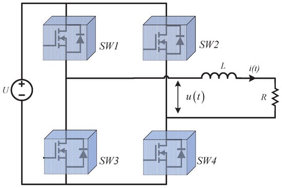
Figure 2.
Schematic of an H-bridge converter.
Switching Sequence Control (SSC): Given a reference current , designing the input sequence from the finite input set and the corresponding time switching sequence satisfying
such that the current can accurately track the reference current .
To achieve this, the discrete-time model of the H-bridge converter is established by considering the switching characteristics of the power devices . By a mathematical transformation, the continuous-time model (1) of the H-bridge converter is rewritten as
Integrating both sides of Equation (4) over gives
It is then easy to deduce that
Clearly for a small sampling period, it has
By substituting Equations (6) and (7) into Equation (5), the discrete model in Equation (4) is obtained
The system in (8) is the discrete-time model for the H-bridge converter. In the next section, a discrete-time model-based solution of the SSC is proposed, which is called dSSC. The proposed method tracks any arbitrary current reference with zero steady-state errors.
3. Discrete Switching Sequence Control Design
The dSSC design proceeds according to the following steps:
Step 1. The input sequence is selected according to
Step 2. The switching time sequence satisfies
Step 3. If are properly designed, the switching sequence controller is given by
In addition, Figure 3 shows the above steps for the dSSC. In Figure 3, the input sequence consists of the converter inputs, and its elements belong to the finite set . The switching time sequence determines the start time and end time of each element of . For example, the beginning and ending times of in the input sequence are and , respectively. When the input sequence and the switching time sequence , are well-designed, the controller is constructed by and , according to Step 3.
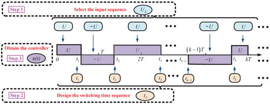
Figure 3.
Step-by-step design of the proposed dSSC.
As follows, the switching time sequence is designed such that tracks the reference without steady-state errors. The tracking error is defined as
From (8), the tracking error at time is defined as
Next, the switching time sequence is designed according to the following two cases. In Case 1, with and is designed, while with and is constructed in Case 2.
Case 1. . In this case, in the time domain satisfies
Then,
This, together with (13), implies
Choosing satisfying
which results in
where is the control parameter and . It is easy to calculate from (17) that
Case 2. . In this case, in the time domain satisfies
Thus,
Submitting (21) into (13) results in
Choosing the switching time such that
it can be observed that
By a simple calculation from (23), it is deduced that
Stability analysis. When the switching time sequence is chosen by Case 1 and Case 2, it yields from (18) and (24) that
For , this yields Equation (27), which states that
With the above dSSC design and analysis, it the theorem follows:
Consider the discrete-time system (8) for the H-bridge converter. If the switching sequence controller is designed by Step 1–Step 3, and the switching time sequence , is chosen by (19) and (25) according to the above Case 1 and Case 2, then
where is the control parameter and .
Equation (28) shows that the proposed method achieves zero steady-state errors. Also, it implies the relationship between the system dynamics and the control parameter . Applying as a criterion for the settling time , it is selected and It has
Hence,
According to (30), the system dynamics are adjustable and the expected settling time is obtained by choosing the control parameter .
Remark 1.
It is observed from Step 3 that the power devices only switch once in a sampling period. However, the classic PWM requires the power devices to switch twice in a sampling period. This means the switching frequency for the dSSC (11) is only half of that for the PWM method.
4. A Special Case: dSSC with One-Sampling-Period Tracking
As a special case, selecting the control parameter is discussed in this section. According to Equation (27), when , it is deduced that
It implies the Equation (31), which states that
(1) This case has zero steady-state error tracking for any arbitrary current references;
(2) This case has significant fast dynamics and its dynamics process is about one sampling period.
In this case, together with (19), (25) and the control parameter , the switching time sequence is deduced as
According to (10), . To limit in such a region, a condition is expected to satisfy
Hence, a conclusion is summarized as follows. Consider the discrete-time system (8) for the H-bridge converter. If the switching sequence controller is designed by Step 1–Step 3, the switching time sequence is chosen by (32) and the condition (33) is satisfied, the current will track the current references without steady-state errors and converge in a sampling period.
In practice, there are some applications where the condition (33) is unsatisfied. In the following, the controller (32) and Step 1–Step 3 with a saturation strategy are proposed to handle this issue.
When the condition (33) is unsatisfied and it results in or , the switching time is designed by a saturation strategy as
With the saturation strategy (34), is set as U or in the time domain , , and the tracking errors reduce in the fastest way. Then, the condition (33) will be satisfied in a certain period, and the proposed method achieves zero steady-state error tracking.
5. Simulation Results
This section presents the simulation results for the proposed dSSC method. The simulation parameters are set as follows: V, , mH, and μs. Figure 4, Figure 5 and Figure 6 are the simulation results of the proposed method.
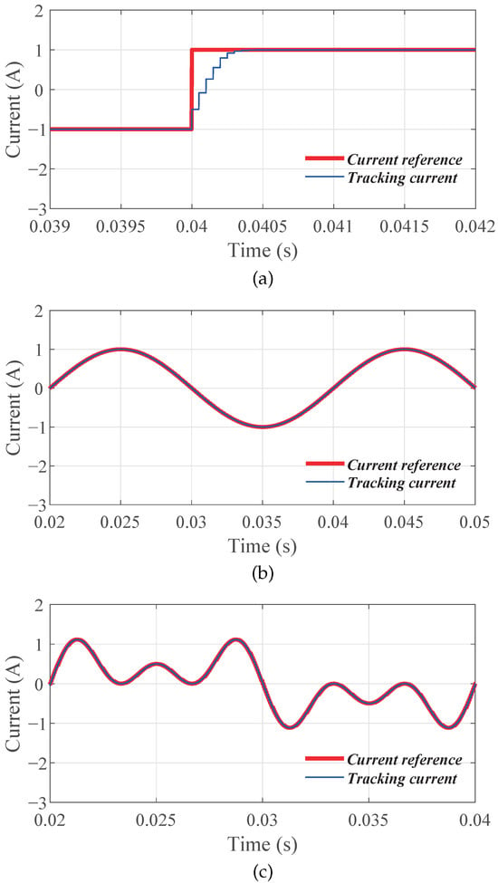
Figure 4.
Tracking performance of the dSSC, (a) the reference is step-change signal, (b) the reference is sinusoidal signal, and (c) the reference contains harmonics.
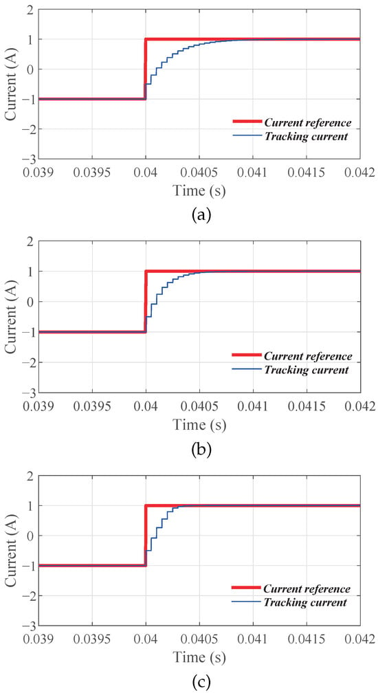
Figure 5.
Dynamic performance of the dSSC with different , (a) , (b) , and (c) .
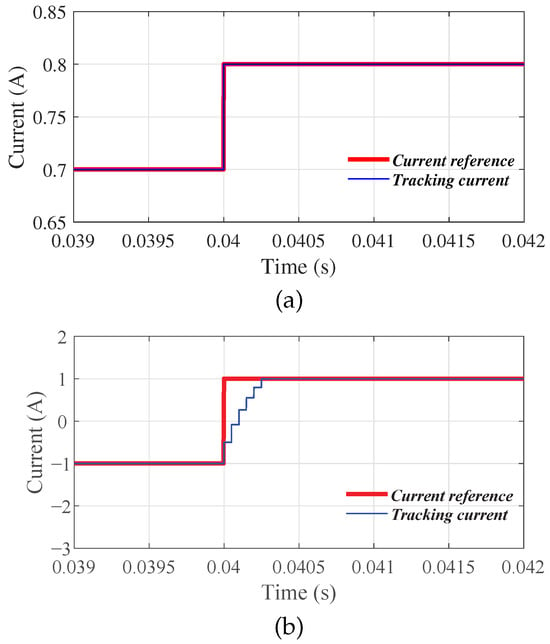
Figure 6.
Performance of the dSSC when , (a) (33) is satisfied, and (b) (33) is unsatisfied.
In Figure 4, the simulation shows the tracking performances of the proposed dSSC, with different references. The control parameter is selected as . In Figure 4a, the current reference is set as a step-change signal. In Figure 4b, the current reference is a sinusoidal signal with its amplitude being . In Figure 4c, the reference is selected as a A sinusoidal signal with A third and A fifth harmonics. Observing In Figure 4b,c, the proposed method achieves zero steady-state-error tracking and it is suitable for different types of references, which is a part of the conclusion in Equation (27).
In Figure 5, the simulations provide the relationships between system dynamics and the control parameter . In Figure 5, the parameter is chosen as , , and , respectively. The simulation results show that the steady-state tracking errors are zero under different control parameters. However, their dynamics are different. It is observed from Figure 5, that a smaller results in faster dynamics, which has been concluded in Equation (27).
Figure 6 shows the performance of the dSSC, with the control parameter . In Figure 6a, the current reference is a step-change from A to A and hence the condition (33) is satisfied. In this case, the current tracking has fast dynamics and its transient process is about one sampling period, which further confirms the results of Equation (31). In Figure 6b, the current reference is a step-change from A to A and the condition (33) is unsatisfied. Observing Figure 6b, its dynamics are slower, being longer than one sampling period but it still converges to the current reference, with a short transient period.
6. Experiment Results
The proposed dSSC was implemented on a TMS320F28379D DSP-based platform. Gate signals were generated by a dedicated control PCB and used to drive the IGBTs forming the H-bridge inverter. Current waveforms were captured with an oscilloscope. The experimental parameters were , , , and μs. The experimental setup is shown in Figure 7.
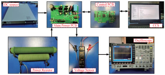
Figure 7.
Experimental setup.
Figure 8 shows the experimental tracking results for three reference signals: a step, a sinusoid, and a sinusoid with harmonics. Figure 8a illustrates that the proposed method exhibits a fast transient response to a step input. Figure 8b,c demonstrate that the controller achieves zero steady-state error when tracking a sinusoidal reference and a sinusoidal reference with harmonic content, respectively. Importantly, Figure 8c indicates that zero steady-state tracking error is preserved even in the presence of harmonics. These observations are consistent with Equation (27).
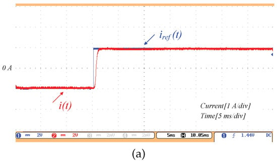
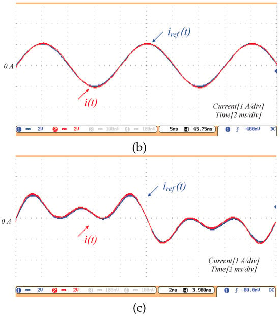
Figure 8.
Experiment results of the tracking performance, (a) the reference is a step, (b) the reference is sinusoidal, and (c) the reference contains harmonics.
Figure 9 provides experiments of the dynamic performances, with different control parameters . Observing Figure 9, it is found that a smaller control parameter leads to faster dynamics, which is also summarized in Equation (27).
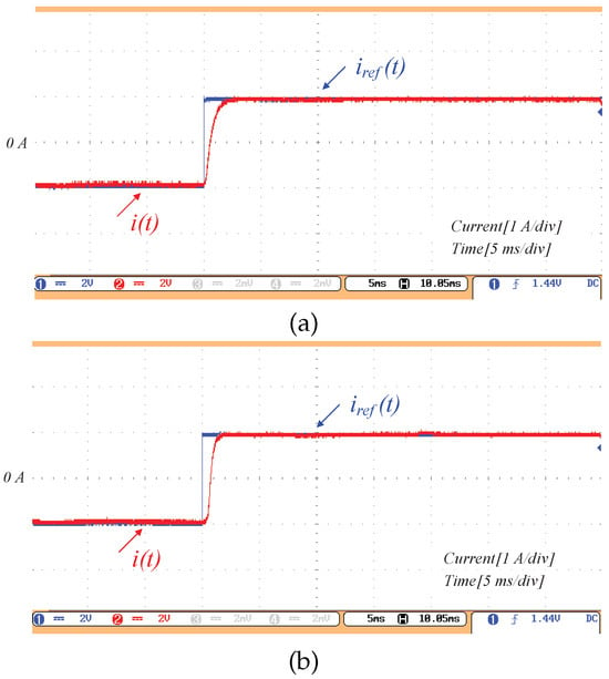
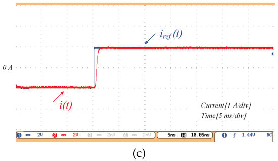
Figure 9.
Experiment results of the dynamic performance with different , (a) , (b) , and (c) .
Figure 10 is the experimental result of the dSSC, with the control parameter . In Figure 10a, the current reference is a step-change from A to A and the condition (33) is satisfied. Hence, a zero steady-state tracking error is achieved within one sampling period. It confirms the conclusion of Equation (31). In Figure 10b, the reference is a step-change from A to A, which causes the condition (33) to be unsatisfied. Hence, the transient process is larger than a sampling period. However, it still achieves accurate tracking with satisfactory dynamics.
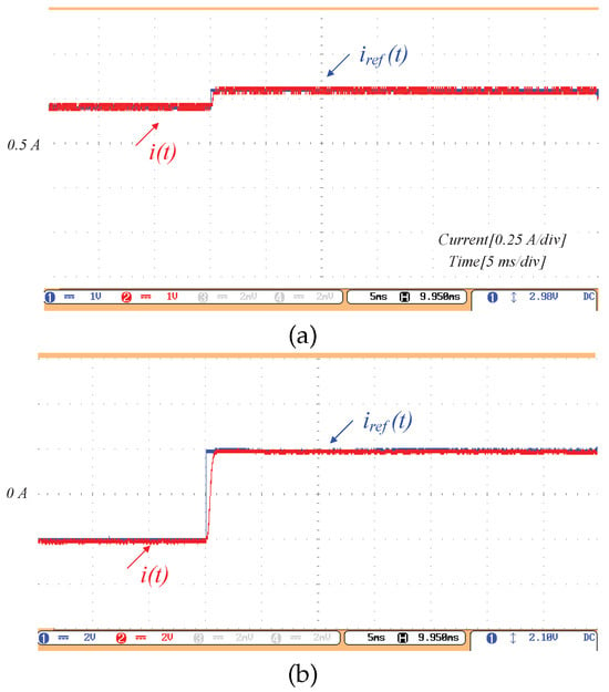
Figure 10.
Experiment Performance of the dSSC when , (a) (33) is satisfied, and (b) (33) is unsatisfied.
7. Conclusions
This paper proposes a dSSC for the H-bridge converters to track current references with zero steady-state errors. The proposed method is universal and it is suitable for arbitrary type references, such as steps, sinusoidal signals, and harmonics. In detail, the discrete model of the H-bridge converters is established, considering the switching characteristics of power devices. Then, the dSSC is provided in a step-by-step way to achieve accurate current tracking. The parameter tuning is also addressed to adjust the dynamic responses. In addition, choosing the control parameter as 0, a special case is discussed deeply. In this case, the system achieves zero steady-state errors within one-sampling-period dynamics, when the condition (33) is satisfied.
Furthermore, the average switching frequency of the proposed method is just half of that for the PWM methods. This reduction lowers switching losses in power devices and decreases overall power dissipation, which in turn reduces maintenance requirements and improves converter efficiency in wind-turbine applications. Simulation and experimental results validate the effectiveness of the proposed approach. However, the proposed dSSC method entails increased computational complexity, and its performance under more complex operating conditions has not yet been evaluated. Future work will therefore concentrate on lowering computational requirements and broadening the controller model to cover more practical scenarios.
Author Contributions
Conceptualization, J.Y. and Z.D.; methodology, J.Y. and X.W.; software, X.W. and G.L.; validation, J.Y., X.W. and G.L.; formal analysis, G.L.; investigation, J.Y., W.H. and C.L.; resources, C.L. and Z.D.; data curation, X.W. and W.H.; writing—original draft preparation, J.Y.; writing—review and editing, Z.D., X.W. and G.L.; visualization, X.W. and G.L.; supervision, Z.D.; project administration, Z.D. All authors have read and agreed to the published version of the manuscript.
Funding
This work was supported by the National Key Research and Development Program of China under Grant 2023YFB4203200.
Data Availability Statement
Data is contained within the article.
Conflicts of Interest
Jiawei Yu and Chao Luo were employed by the State Key Laboratory of HVDC, Electric Power Research Institute, China Southern Power Grid. The remaining authors declare that the research was conducted in the absence of any commercial or financial relationships that could be construed as a potential conflicts of interest.
Abbreviations
The following abbreviations are used in this manuscript:
| DSSC | Discrete switching sequence control |
| PWM | Pulse width modulation |
| SPWM | Sinusoidal pulse width modulation |
| SVPWM | Space vector pulse width modulation |
References
- Blaabjerg, F.; Yang, Y.; Yang, D.; Wang, X. Distributed powergeneration systems and protection. Proc. IEEE 2017, 105, 1311–1331. [Google Scholar] [CrossRef]
- Meyers, J.; Bottasso, C.; Dykes, K.; Fleming, P.; Gebraad, P.; Giebel, G.; Göçmen, T.; Van Wingerden, J.W. Wind farm flow control: Prospects and challenges. Wind Energy Sci. Discuss. 2022, 7, 2271–2306. [Google Scholar] [CrossRef]
- Ligęza, P. Basic, Advanced, and Sophisticated Approaches to the Current and Forecast Challenges of Wind Energy. Energies 2021, 14, 8147. [Google Scholar] [CrossRef]
- Fu, X.; Sun, J.; Huang, M.; Tian, Z.; Yan, H.; Iu, H.H.C.; Hu, P.; Zha, X. Large-signal stability of grid-forming and grid-following controls in voltage source converter: A comparative study. IEEE Trans. Power Electron. 2021, 36, 7832–7840. [Google Scholar] [CrossRef]
- Li, G.; Luo, A.; He, Z.; Ma, F.; Chen, Y.; Wu, W.; Zhu, Z.; Guerrero, J.M. A DC hybrid active power filter and its nonlinear unified controller using feedback linearization. IEEE Trans. Ind. Electron. 2021, 68, 5788–5798. [Google Scholar] [CrossRef]
- do Carmo Mendonça, D.; Cupertino, A.F.; Pereira, H.A.; Teodorescu, R. Minimum cell operation control for power losses reduction in MMC-based STATCOM. IEEE J. Emerg. Sel. Top. Power Electron. 2021, 9, 1938–1950. [Google Scholar] [CrossRef]
- Xiong, Y.; Jiang, D.; Shuai, Y.; You, J.; Liu, Z.; Sun, W. Multiphase Parallel Winding Current Source Inverter With High Maximum Modulation Index. IEEE Trans. Power Electron. 2025, 40, 13217–13230. [Google Scholar] [CrossRef]
- Song, M.; Wu, H.; Qin, S.; Xing, Y. Common-Mode Noise Characterization and Reduction for Isolated PWM DC-DC Converters With Stacked-Rectifiers. IEEE Trans. Power Electron. 2025, 40, 11021–11031. [Google Scholar] [CrossRef]
- Rocabert, J.; Luna, A.; Blaabjerg, F.; Rodríguez, P. Control of power converters in ac microgrids. IEEE Trans. Power Electron. 2012, 27, 4734–4749. [Google Scholar] [CrossRef]
- Kolar, J.; Friedli, T.; Rodriguez, J.; Wheeler, P.W. Review of three-phase PWM AC/AC converter topologies. IEEE Trans. Ind. Electron. 2011, 58, 4988–5006. [Google Scholar] [CrossRef]
- Teodorescu, R.; Liserre, M.; Rodriguez, P. Grid Converters for Photovoltaic and Wind Power Systems; John Wiley & Sons: Hoboken, NJ, USA, 2011. [Google Scholar]
- Han, L.; Liang, L.; Kang, Y.; Qiu, Y. A review of SiC IGBT: Models, fabrications, characteristics, and applications. IEEE Trans. Power Electron. 2021, 36, 2080–2093. [Google Scholar] [CrossRef]
- Wang, Z.; Luo, Q.; Wei, Y.; Mou, D.; Lu, X.; Sun, P. Topology analysis and review of three-port dcdc converters. IEEE Trans. Power Electron. 2020, 35, 11783–11800. [Google Scholar] [CrossRef]
- Bhattacharjee, A.K.; Kutkut, N.; Batarseh, I. Review of multiport converters for solar and energy storage integration. IEEE Trans. Power Electron. 2019, 34, 1431–1445. [Google Scholar] [CrossRef]
- Li, A.; Jiang, D.; Liu, Z.; Sun, X. Generalized PWM method for seriesend winding motor drive. IEEE Trans. Power Electron. 2021, 36, 4452–4462. [Google Scholar] [CrossRef]
- Huang, Y.; Walden, J.; Foote, A.; Bai, H.; Lu, D.; Jin, F.; Cheng, B. Analytical characterization of CM and DM performance of three-phase voltage-source inverters under various PWM patterns. IEEE Trans. Power Electron. 2021, 36, 4091–4104. [Google Scholar] [CrossRef]
- Yong, Y.; Wen, H.; Fan, M.; Xie, M.; Rodriguez, J. Computation efficient model predictive control with common-mode voltage elimination for five-level anpc converters. IEEE Trans. Transp. Electrif. 2020, 6, 970–984. [Google Scholar] [CrossRef]
- Xia, Y.; Peng, Y.; Yang, P.; Yu, M.; Wei, W. Distributed coordination control for multiple bidirectional power converters in a hybrid ac/dc microgrid. IEEE Trans. Power Electron. 2017, 32, 4949–4959. [Google Scholar] [CrossRef]
- Yang, Y.; Wen, H.; Fan, M.; Xie, M.; Chen, R.; Wang, Y. A constant switching frequency model predictive control without weighting factors for t-type single-phase three-level inverters. IEEE Trans. Ind. Electron. 2019, 66, 5153–5164. [Google Scholar] [CrossRef]
- Vorperian, V.; Tymerski, R. Equivalent circuit models for resonant and PWM switches. IEEE Trans. Power Electron. 1989, 4, 205–214. [Google Scholar] [CrossRef]
- Xu, J.; Guo, J.; Zhang, L.; Xu, G.; Su, M. PWM Controlled Single Stage Resonant Converter With Multiwinding Coupled Inductor. IEEE Trans. Power Electron. 2025, 40, 16651–16663. [Google Scholar] [CrossRef]
- Yang, S.; Zheng, P.; Sui, Y.; Tong, C.; Wang, M. Carrier-Based PWM Technique and Extended State Observer-Based Current Control Scheme for Current-Source Inverter-Fed Five-Phase PMSM Drives. IEEE Trans. Ind. Electron. 2024, 71, 6635–6646. [Google Scholar] [CrossRef]
- Tymerski, R.; Vorperian, V. Nonlinear modeling of the PWM switch. IEEE Trans. Power Electron. 1989, 4, 225–233. [Google Scholar] [CrossRef]
- Xu, T.; Gao, F. Global synchronous pulse width modulation of distributed inverters. IEEE Trans. Power Electron. 2016, 31, 6237–6253. [Google Scholar] [CrossRef]
- Wang, K.; Zheng, Z.; Xu, L.; Li, Y. Neutral-point voltage balancing method for five-level NPC inverters based on carrier-overlapped PWM. IEEE Trans. Power Electron. 2021, 36, 1428–1440. [Google Scholar] [CrossRef]
- Kolar, J.W.; Ertl, H.; Zach, F.C. Analysis of on- and off-line optimized predictive current controllers for PWM converter systems. IEEE Trans. Power Electron. 1991, 6, 451–462. [Google Scholar] [CrossRef]
- Raju, G.S.N.; Doradla, S. An LCL resonant converter with PWM control-analysis, simulation, and implementation. IEEE Trans. Power Electron. 2002, 10, 164–174. [Google Scholar] [CrossRef]
- Bahrami, A.; Narimani, M. A sinusoidal pulsewidth modulation (SPWM) technique for capacitor voltage balancing of a nested t-type four-level inverter. IEEE Trans. Power Electron. 2019, 34, 1008–1012. [Google Scholar] [CrossRef]
- Yan, Q.; Zhou, Z.; Wu, M.; Yuan, X.; Zhao, R.; Xu, H. A simplified analytical algorithm in abc coordinate for the three-level SVPWM. IEEE Trans. Power Electron. 2021, 36, 3622–3627. [Google Scholar] [CrossRef]
Disclaimer/Publisher’s Note: The statements, opinions and data contained in all publications are solely those of the individual author(s) and contributor(s) and not of MDPI and/or the editor(s). MDPI and/or the editor(s) disclaim responsibility for any injury to people or property resulting from any ideas, methods, instructions or products referred to in the content. |
© 2025 by the authors. Licensee MDPI, Basel, Switzerland. This article is an open access article distributed under the terms and conditions of the Creative Commons Attribution (CC BY) license (https://creativecommons.org/licenses/by/4.0/).