Abstract
This study presents the design and experimental evaluation of a 10 MHz voltage regulator module (VRM) that incorporates a solenoid inductor embedded within a printed circuit board (PCB). To verify the performance of the inductor, a test PCB was fabricated and characterized using a vector network analyzer (VNA), with measurement data processed through 2x-thru de-embedding technique. A 10 MHz VRM was then implemented to assess the impact of the embedded inductor on system efficiency. Comparative measurements were conducted between two VRMs—one employing a surface-mounted (SMT) inductor and the other a PCB-embedded inductor. The SMT-based system achieved a peak efficiency of 65.24% at a load current of 800 mA, whereas the PCB-embedded inductor version reached 70.43% at 900 mA, reflecting an improvement of 5.19%. The VRM with an embedded inductor experienced less efficiency degradation under heavy load conditions, demonstrating superior energy delivery stability. These findings confirm the practical benefits of integrating solenoid inductors within a PCB for high-frequency, high-efficiency power conversion.
1. Introduction
High performance voltage regulator modules (VRMs) are key technologies in various industries, including high performance computing and heterogeneous integration. Recently, VRMs have been advancing towards higher switching frequencies while maintaining high efficiency and power density, further reducing the size of power supply system [1,2]. As switching frequency increases, the amount of energy stored per cycle decreases, allowing the size of passive components required to deliver the same output power to be reduced. Accordingly, the integration of the passive components on substrates such as chips, packages, and printed circuit boards (PCBs) has become increasingly important in modern VRM design.
In recent years, integrated voltage regulator (IVR) technology, which integrates formerly off-chip components of VRM like inductors and capacitors in a die, has become a major focus of research [3,4,5,6,7,8]. IVRs operate at high switching frequencies and embed passive components on the die or package for efficient power management. Embedding passive components within the die or package enables voltage regulation to occur closer to the point of load, thereby reducing the need for multi-stage voltage regulators (VRs) on the PCB. This close integration facilitates shared power delivery among multiple functional blocks, decreasing the number of required VRs and minimizing the system footprint. However, as inductors and capacitors are moved from the PCB onto the package substrate, integrated voltage regulators (IVRs) face increased challenges in thermal management and routing complexity. Compared with PCB-mounted VRMs, IVRs require more bumps, and this can lead to greater complexity in package design. The integration of passive components within the PCB substrate enables higher power density and improved electrical characteristics, including reduced parasitics and enhanced current handling, which are critical for high-performance power conversion systems [9,10,11].
Previous research on inductors for IVRs has focused on maximizing inductance per unit area and exploring the use of magnetic materials. Typical inductor geometries, include toroidal, spiral, and solenoidal structures, each of which offers various electromagnetic properties and implementation trade-offs [12,13,14,15,16,17]. Toroidal inductors suffer from low fill factors due to the need for vias at the inner and outer edges. Spiral inductors, which provide high quality factors, are widely used in on-chip environments but induce vertical flux across metal layers, which can cause interlayer coupling. The induced vertical flux requires additional ground layers to mitigate interference. In contrast, solenoidal inductors provide greater structural flexibility because both the conductor length and the cross-sectional area can be independently adjusted. This geometric tunability directly influences inductance, resistance, and quality factor, thereby enabling more precise optimization of inductor performance while also allowing efficient adaptation to layout and packaging constraints [18].
Furthermore, PCB-embedded solenoid inductors allow for more flexible designs that can be customized to meet specific requirements. Placing the inductors within the PCB reduces the number of discrete components and improves board area usage. From a performance standpoint, PCB-embedded inductors offer advantages in minimizing parasitic effects. In VRMs operating at high frequencies, parasitic resistance and inductance caused by external wiring and soldering can degrade system efficiency. By integrating inductors directly within the PCB, parasitic elements can be effectively reduced, leading to improved high-frequency performance.
The PCB-embedded solenoid inductor structure used in this research was proposed by reference [19]. This paper focuses on the experimental verification and system-level evaluation of the proposed structure. The fabricated inductor was modeled using Ansys HFSS and evaluated using 2x-thru de-embedding techniques. To evaluate the impact of PCB-embedded inductors on power management integrated circuits (PMICs), a VRM operating at 10 MHz was designed, and its efficiency was compared across different inductor types. The measurement results confirmed that the PCB-embedded inductor reduces system footprint and enhances integration, offering a practical substitute for traditional components.
This paper is organized as follows: Section 2 discusses the method for determining the required inductance for the VR and explores the relationships between VR performance and inductor characteristics. Section 3 describes the design of the inductor, along with simulation and measurement results. Section 4 describes the integration of the proposed structure into the PCB and validates the results by evaluating the VR operation. Section 5 concludes the paper.
2. Inductor Design and Structure
Selection of an appropriate inductor, including die-level power integrity and package-level PDN integration considerations, is important to the overall design of a PMIC. Design metrics for inductors include direct current (DC) resistance, volume, inductance, and quality factor. These characteristics directly affect the performance of the VRM in terms of efficiency, output ripple, and transient response. In the hard-switching buck converter topology, the switching duty cycle (D) is calculated using Equation (1), and the required inductance for continuous conduction mode operation is obtained using Equation (2).
Here, and denote the on-resistance of the high-side and low-side switches, respectively. represents the direct current (DC) resistance of the inductor, and indicates the ripple magnitude of the inductor current, is the input voltage, is the target output voltage. Additionally, represents the switching frequency, and is assumed to be approximately equal to the load current for analysis purposes. Simulation results of the inductance requirement across varying switching frequencies confirm that, at 10 MHz, an inductance value below 35 nH is needed if the ripple current exceeds 65% of the output current [20]. Based on this analysis, a top-down design approach was adopted in this work, where the inductance was selected by considering the target operating frequency and duty cycle. As a solution to the trade-off between size, stability, and response time, a multi-phase topology was introduced. In this configuration, multiple phases operate interleaved with defined phase shifts, improving the effective ripple frequency and enabling the use of lower inductance values without sacrificing output performance. In particular, in a two-phase interleaved structure, phase interference effects effectively multiply the ripple frequency, allowing for compact inductors while maintaining both output stability and fast transient response.
Based on these characteristics, we designed a two-phase voltage regulator and modeled a suitable inductor. A multi-radius multi-path (MRMP) structure was designed and used, as an extension of a nested-type air-core solenoid inductor [19,21,22]. As shown in Figure 1a, the MRMP structure forms a two-port inductor using a continuous solenoidal winding that is routed in a folded manner to extend the current path. The magnetic fluxes of the windings reinforce each other in the same direction, resulting in an increased magnetic flux within the core. The two solenoids are connected at one end, effectively forming a single inductor. Due to the inductor structure being terminated at one end, port 1 and port 2 are positioned on the same side. Figure 1b presents a top view of the structure and Figure 1c is a cross-sectional view. To reduce parasitic capacitance between adjacent traces, this MRMP inductor geometry was designed to prevent overlap.
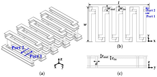
Figure 1.
Designed multi-radius multi-path structure inductor (a) overall view, (b) top view, and (c) cross-section view.
However, because of the nested configuration, the total routing length is nearly doubled that of a conventional inductor with the same footprint. As a result, the nested inductor achieves a higher inductance but exhibits a lower quality factor. To mitigate this trade-off, the outer and inner windings can be independently adjusted, which helps to relatively alleviate the aforementioned limitations. Specifically, the outer metal lines are adjusted for width , and thickness , while the inner windings are tuned separately using and . This structural adjustment improves the quality factor at high frequencies, offering improved electrical performance. The designed inductor was subsequently modeled and simulated using Ansys HFSS [23].
The MRMP inductor was designed with multiple turns distributed across the top and bottom layers of the PCB. From Equation (2) we can derive the inductance value required for VR with 10 MHz switching frequency to be 22 nH. The key structural parameters, such as metal line widths, layer thicknesses, and via dimensions, are summarized in Table 1. The overall size of the inductor, including the embedded structure, measured 5.7 mm × 9 mm × 1.6 mm. During the structural design process, the routing aspect ratio was revised in accordance with the manufacturing limitations, such as fixed dielectric and copper thicknesses and the minimum metal line spacing permitted by the PCB fabrication rules.

Table 1.
Structural parameters of the designed inductor.
In addition to its electrical performance, the embedded solenoid inductor is expected to provide improved electromagnetic compatibility (EMC) characteristics. The solenoid geometry naturally minimizes the current loop area, which helps reduce radiated electromagnetic interference (EMI). Furthermore, embedding the inductor within the PCB stack allows it to be surrounded by multiple copper planes, such as power or ground layers, which can act as partial electromagnetic shields. This structural configuration helps contain electromagnetic fields and restrict radiation paths. The use of ground vias around the embedded inductor further reinforces this effect by containing the fields and reducing leakage at the board edges.
3. PCB-Embedded Inductor Measurement Method and Results
In this section, we show the de-embedding technique and the measurement results of the PCB embedded inductor. The 2x-thru de-embedding technique was used to extract the characteristics of the device under test (DUT), which includes additional fixture components, with the required de-embedding model shown in Figure 2. The DUT refers to the PCB-embedded MRMP inductor. The 2x-thru de-embedding technique requires two PCB test coupons. The first PCB test case, shown in Figure 2a, includes the DUT along with the additional extension lines necessary for measurement. The second PCB test case, as in Figure 2b, consists only of the additional extension lines without the DUT. Using the S-parameters of these two structures, the intrinsic characteristics of the DUT can be accurately extracted. For accurate extraction, the extension lines and connectors, excluding the DUT, must be designed symmetrically. This symmetry ensures that the S-parameters can be extracted effectively without distortion from the surrounding structure.

Figure 2.
The presented 2x-thru de-embedding model (a) fixture with DUT and (b) symmetrical extension line fixture without DUT.
The de-embedding is performed from the following procedure [24,25]. First, measurement results were obtained in the frequency domain in the form of S-parameters. These were then converted to T-parameters, which are more suitable for de-embedding analysis and can be used to extract the characteristics of the DUT. The transformed T-parameters allow for the removal of the external fixture effects, which isolate the intrinsic characteristics of the DUT. The measurement data are expressed by Equations (3) and (4). The fixtures, excluding the inductor, were designed to be symmetrical to have identical transfer functions.
Here, represents the T-matrix corresponding to the inductor, and denotes that of the fixture excluding the inductor. The T-matrix of the DUT can be calculated from Equation (5).
In the final step, is converted back into S-parameters to obtain the final result, . In this work, the short-open-load-through (SOLT) calibration method was applied to effectively eliminate system-induced measurement errors and ensure a reliable data. The complete measurement PCB used for inductor S-parameter characterization is shown in Figure 3. The PCB has dimensions of 37 mm × 38.5 mm and features symmetrical routing across the top and bottom layers to ensure balanced measurement conditions. To minimize the influence of the adaptor and fixture on the DUT response, the identical extension lines are implemented on both sides of the DUT as shown in Figure 3a [26,27]. This design satisfies the assumption of symmetry required for accurate 2x-thru de-embedding, as shown in Figure 2. The DUT region and measurement ports are illustrated in Figure 3b.
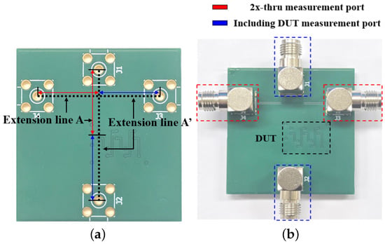
Figure 3.
PCB including the MRMP inductor (a) extension line design and (b) two measurement fixtures.
Figure 4 shows the comparison of the S-parameters obtained from fixture-only measurements and fixture combined with DUT measurement results. The measured S-parameters were extracted as s2p files and then processed and analyzed in the MATLAB R2020b environment. All data were organized in a two-port S-parameter format at a frequency of 0 to 1 GHz.
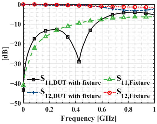
Figure 4.
Comparison of measured S-parameters of the PCB-embedded inductor.
De-embedding was performed based on the two previous measurement datasets, and the comparison with full-wave simulation results is shown in Figure 5. In Figure 5a, both and exhibit a sharp decrease in magnitude at a specific frequency band, which may indicate the presence of resonance or impedance mismatches. In contrast, the simulation results, which are based on ideal conditions, do not show such resonant behavior. Figure 5b presents the comparison of and . Around the VR operation frequencies of 10 MHz, the difference between the two is minimal, while the simulation results show little variation with increasing frequency, the de-embedded measurements reveal a growing discrepancy as the frequency increases. The discrepancy between the simulated and post de-embedding measured inductance is attributed to several factors. Differences in the dielectric constant and magnetic permeability of the substrate material used in the simulation compared to the actual fabricated PCB can lead to variations, especially at high frequencies where such parameters have a significant impact. In addition, manufacturing tolerances in the PCB fabrication process, such as variations in trace width, spacing, and conductor thickness, can also affect the resulting inductance. Lastly, although de-embedding was applied, residual parasitic elements from the measurement equipment, pads, and probes may not have been fully eliminated, which could introduce further error. However, near the design frequency of 10 MHz, these discrepancies have a negligible impact on the target specifications and application. The deviation observed above 800 MHz does not result in meaningful performance degradation and is considered to be within an acceptable range. Importantly, around the inductor design target frequency, which is the VR switching frequency of 10 MHz, the observed deviations at frequencies above 800 MHz had a negligible impact on the intended design and application and can be regarded as acceptable.
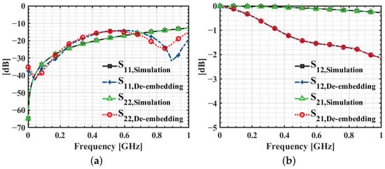
Figure 5.
Comparison of de-embedded and simulated S-parameters of the PCB-embedded inductor (a) and (b) and .
The inductance can be obtained by converting the two-port S-parameters into Y-parameters, as expressed by Equation (6):
where L can be calculated by dividing the imaginary part of with . Figure 6 shows the comparison of the inductance values obtained from simulation and the de-embedded result. Based on the measurements from the two PCB configurations, the de-embedded S-parameters were extracted and compared with the results obtained from HFSS. Here, the HFSS model includes only the fixture without the inductor. The inductance extracted by the de-embedding process was 23.89 nH, an error of approximately 6.5% compared with the simulation results, confirming the validity of the de-embedding technique. This structure was integrated in PCB to be used as the inductor for the VRM, which will be explained in the next section.
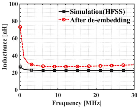
Figure 6.
Inductance comparison between the measurement result after de-embedding and HFSS simulation.
4. VRM Measurement Results with a PCB-Embedded Inductor
4.1. Measurement Setup
A step-down VRM operating at a fixed switching frequency was designed based on pulse width modulation and a continuous conduction mode. Figure 7 shows the design of the VR chip, with Figure 7a showing the top-level schematic with two phases after configuring the control block using current mode control and pulse width modulation. The chip was designed to exclude passive components such as the output capacitor, feedback loop voltage divider, and error amplifier compensation elements. The main specifications of the designed VRM are an input voltage of 5 V, an output voltage of 1.8 V, and a switching frequency of 10 MHz with two phases. The design targeted a maximum output current of 2 A, and the output voltage ripple was specified not to exceed 50 mV. The fabricated die is shown in Figure 7b, with an overall die size of 5 mm × 2.5 mm, fabricated using a 180 nm BCDMOS process.
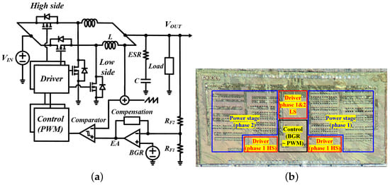
Figure 7.
VRM design (a) top schematic (b) die photo.
Two types of PCBs were used for the fabricated VRM performance comparison and measurement, as shown in Figure 8. Both PCBs were designed with key test points for chip-level evaluation, including the switching node, output node, and feedback node. The PCB incorporating the embedded inductor had overall dimensions of 80 mm × 80 mm, while the SMT-based board was fabricated with a slightly larger footprint. The increased size of the SMT board reflects its role as an initial evaluation platform, where additional chip- and switch-level access points were incorporated to facilitate early-stage functional verification and debugging. The output node was used for voltage and current monitoring in efficiency measurements, the switching node for verifying proper phase interleaving, and the feedback node for confirming duty cycle and voltage division accuracy. Figure 8a employs a commercial surface-mounted (SMT) inductor, the Murata LQW2UAS22NJ00L, rated at 22 nH with a maximum continuous current of 1 A and a supported switching frequency of up to 20 MHz. This component was selected to ensure compatibility with the voltage regulator design and to provide a fair, application-relevant comparison with the PCB-embedded MRMP inductor.
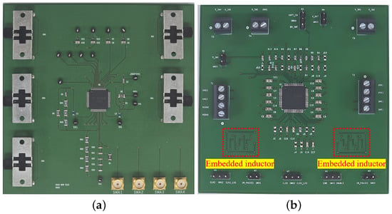
Figure 8.
PCBs used for measurement (a) with SMT inductors (b) with embedded inductors.
The PCB shown in Figure 8b uses a PCB-embedded MRMP inductor instead of the commercial SMT inductor. The required supply voltages, 1.8 V for the digital block and 5 V for the side drivers and input, were supplied through two-pin and four-pin terminals, respectively, while a three-pin header with a central ground was used for stable measurements at critical nodes. Decoupling capacitors were placed close to the chip’s power input pins, and additional jumpers were included for fine adjustment at nodes such as analog compensation and feedback. The MRMP inductor required at least six PCB layers, so the test PCB was designed with a six layer stack. To minimize parasitic components and current loop effects, parallel trace routing was employed, and critical current paths were implemented with wider traces on designated layers.
The PCB layer stack introduces inherent design trade-offs that must be carefully considered. In this work, the prototype with the embedded MRMP inductor was implemented on a six-layer PCB to ensure consistent routing and reliable performance; however, comparable designs can also be realized on a four-layer stack with some limitations, while the use of six layers inevitably increases cost and fabrication complexity, it provides several technical advantages, including enhanced routing flexibility, reduced parasitic inductance and resistance, improved power conversion efficiency, and a smaller overall board footprint. In addition, the multilayer configuration contributes to improved heat spreading, which was confirmed by thermal measurements showing a lower peak temperature in the embedded design compared with the SMT counterpart.
4.2. Measurement Results
Figure 9 shows the measured steady-state switching node voltage waveforms of the VRM is working on a PCB with an embedded inductor, as shown in Figure 8b. The output voltage remained stable at 1.8 V with a 5 V input, and the ripple voltage was 90 mV, consistent with the initial design target. The waveforms also confirmed that the switching nodes of each phase operate with a 100 ns period and did not overlap, indicating a proper interleaved operation. To prevent a shoot-through, which can damage the power MOSFETs due to overlap between high-side and low-side conduction, a fixed dead time was implemented during the design phase.
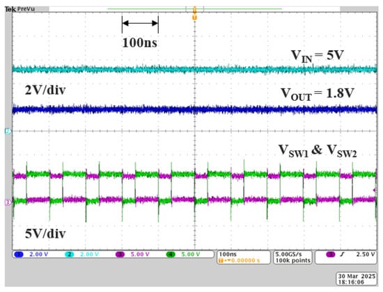
Figure 9.
Steady-state waveforms of VRM with PCB-embedded inductors.
Figure 10 shows the measured load transient responses of the VRM using the PCB-embedded inductor. The load current steps were set to 0.1 A and 1 A, corresponding to 5% and 50% of the maximum output current of 2 A, respectively [28,29,30,31]. Figure 10a shows the response to an increase in load from 0.1 A to 1 A, with a peak voltage deviation of 180 mV. The voltage recovered to its steady-state level within approximately 20 ns. In contrast, Figure 10b shows the response to a decrease in load from 1 A to 0.1 A, with a peak deviation of 150 mV was observed. In this pull-down condition, the recovery time was also approximately 20 ns, with a slightly lower peak deviation compared to the load case.

Figure 10.
Load transient response measurement waveforms of VRM with PCB-embedded inductors (a) loaded with current step up (b) unloading.
In addition to the efficiency improvement, the stability of the proposed system was analyzed from the transient response measurements. The observed step responses can be well approximated by a standard second-order closed-loop model, where the damping ratio is related to the measured overshoot , as expressed in Equation (7). Here, denotes the maximum peak overshoot ratio of the output voltage relative to its steady-state value.
The measured transient undershoot was observed to be between 8% and 10% of the nominal output voltage. This corresponds to a damping ratio in the range of 0.5 to 0.6. The transient response measurements indicate that the system behaves like a well-damped response with negligible ringing. This confirms that the compensation network implemented around the error amplifier provides sufficient phase margin and loop stability for operation at 10 MHz. Together with the fast settling behavior, these results confirm that the embedded inductor enables stable closed-loop operation while maintaining robust dynamic performance in the VRM design.
Figure 11 compares the measured power conversion efficiency of the designed VRM as a function of load current for two configurations, one with a commercial SMT inductor and the other with the proposed PCB-embedded MRMP inductor. The efficiency of the SMT-based VRM achieved a peak efficiency of 65.24% at approximately 800 mA, while the efficiency of the PCB using the proposed inductor reached 70.43% at 900 mA, representing a 5.19% improvement. Although conversion efficiency generally decreases with increasing load current, the embedded inductor exhibited a slower rate of efficiency degradation, indicating improved loss mitigation. This result suggests that the PCB-embedded MRMP inductor provides more stable power delivery and suppresses conduction and switching losses more effectively under heavy load conditions.
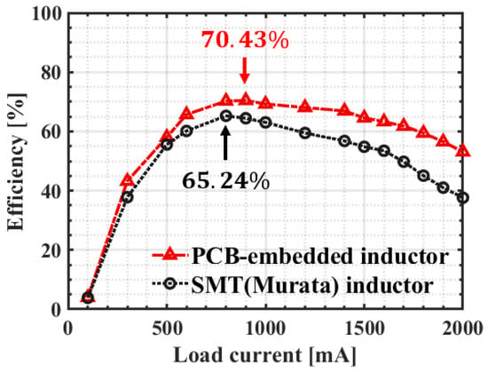
Figure 11.
VRM efficiency comparison.
Figure 12 shows the comparison of the inductance and quality factor of the PCB-embedded inductor and commercial SMT inductor, which are key performance indicator in voltage regulator applications, while the performance data of the SMT inductor were provided by Murata Electronics, values below 10 MHz were not specified in the datasheet. At 10 MHz, the measured quality factor of the PCB-embedded MRMP inductor was 22.24, significantly higher than the 12.94 of the SMT inductor. This indicates that the PCB-embedded MRMP inductor incurs less energy loss per cycle at the same frequency, making it more advantageous for high-frequency power conversion applications. In terms of inductance, the PCB-embedded inductor measured 23.89 nH and the SMT inductor measured 21.78 nH, both values being close to the target inductance of 22 nH. Although the PCB-embedded inductor showed relatively greater variation due to PCB processing and manufacturing tolerances, its flexible structural design and higher quality factor suggest potential benefits in power system applications.
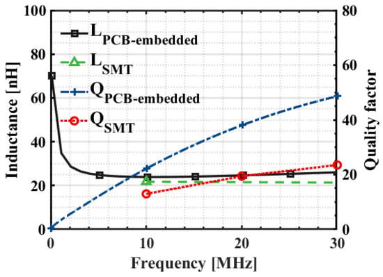
Figure 12.
Measured inductance and Q-factor comparison between PCB-embedded MRMP and SMT.
In addition to electrical performance, the thermal behavior of the embedded inductor was evaluated to assess potential reliability concerns. Since embedding modifies the heat dissipation path compared with SMT parts, thermal tests were conducted under identical operating conditions using an IR camera (AT313X). The measurement was performed by operating the VRM at the load current corresponding to peak efficiency for three minutes, after which a thermal snapshot was captured to record the stabilized temperature rise. The initial condition was room temperature of 25 °C, and all reported values represent the temperature rise relative to this baseline.
The PCB with a commercial SMT inductor exhibited a maximum temperature rise of 90.7 °C, whereas the PCB incorporating the embedded MRMP inductor showed a lower peak of 65.3 °C. This difference is primarily attributed to the reduced core loss of the embedded structure and the enhanced heat spreading provided by the multilayer stack-up. In the prototype boards, the SMT inductor was mounted closer to the chip due to the layout constraints of the commercial device and the need for direct switching-node access, while the MRMP inductor board adopted a slightly different routing arrangement for measurement convenience. This position difference likely increased thermal coupling in the SMT case. Even with this factor considered, the embedded MRMP inductor consistently demonstrated lower peak temperature and a more uniform thermal distribution. These results indicate that, under the evaluated conditions, the proposed PCB-embedded MRMP inductor improves efficiency, quality factor, and thermal behavior, while also providing greater thermal margins and potential long-term reliability benefits.
In summary, the measurement results demonstrate that the proposed PCB-embedded MRMP inductor enables stable VRM operation with a regulated output voltage of 1.8 V and proper interleaving between phases. Transient response tests confirmed rapid recovery within tens of nanoseconds and limited voltage deviation, corresponding to a damping ratio in the range of 0.5 to 0.6, which indicates sufficient loop stability at 10 MHz operation. Compared with a commercial SMT inductor, the embedded MRMP structure improved peak efficiency by 5.2% and maintained superior efficiency in the high-current region. The embedded inductor also exhibited a higher quality factor at 10 MHz, supporting lower energy loss per cycle. Finally, thermal tests verified that the PCB-embedded device provides more favorable heat spreading and reduced temperature rise, highlighting its potential for reliable operation in next-generation VRM applications, including multiphase integration, 2.5D packaging, and vertical power delivery.
5. Conclusions
In this work, a PCB-embedded MRMP inductor was designed, fabricated, and experimentally validated for VRM applications. The modeling accuracy was confirmed through 2x-thru de-embedding, which yielded a maximum deviation of 6.5% between measured and simulated inductance values, verifying the reliability of the design methodology. When integrated into a 10 MHz two-phase VRM, the proposed inductor enabled a peak conversion efficiency of 70.4% at 900 mA, representing a 5.2% absolute improvement over a commercial SMT inductor, which achieved 65.2% at 800 mA under identical operating conditions. Furthermore, across the high current region exceeding 1 A, the embedded inductor consistently sustained higher efficiency with a reduced degradation rate, demonstrating its effectiveness in mitigating conduction and switching losses under heavy load operation. Across the operating range from 0 A to 2 A, the PCB-embedded MRMP inductor consistently outperforms the SMT counterpart, delivering approximately 1.1 times larger enclosed efficiency area and thereby reducing cumulative power loss, with the relative benefit becoming more pronounced at higher load currents. Beyond efficiency, transient response tests demonstrated undershoot limited to approximately 10% and settling within 40–60 ns, confirming sufficient damping and robust loop stability at 10 MHz. The solenoidal geometry and minimized current loop area inherently mitigate EMI, while multilayer copper planes provide partial shielding compared with SMT inductors. The superior efficiency characteristics across the full load range translate into improved thermal margins, enhanced reliability, and better suitability for high-current VRM applications. Such attributes are particularly advantageous in advanced platforms, where power density, layout compactness, and long-term energy savings are critical.
Author Contributions
G.K. and J.H. contributed to the writing of this article. G.K. and. S.K. contributed to the primary idea of this research. G.K. performed the measurement and design. J.H. performed the validation and visualization. This research was planned and executed under the supervision of and S.K. All authors have read and agreed to the published version of the manuscript.
Funding
This work was supported in part by Samsung Electronics Co., Ltd. under Grant No. IO201209-07919-01, and in part by the National Research Foundation (NRF) of Korea grant funded by the Korean Government (MSIT) under Grant RS-2020-NR049544, RS-2025-16067451.
Data Availability Statement
The original contributions presented in this study are included in the article. Further inquiries can be directed to the corresponding author.
Acknowledgments
The chip fabrication and EDA tools were supported by the IC Design Education Center (IDEC), Republic of Korea.
Conflicts of Interest
Author Jisoo Hwang was employed by the company Samsung Electronics. The remaining authors declare that the research was conducted in the absence of any commercial or financial relationships that could be construed as a potential conflicts of interest. The authors declare that this study received funding from the company Samsung Electronics. The funder was involved only in providing financial support for PCB and IC fabrication used in the test.
References
- Khorasani, R.R.; Li, X.; Kim, J.W.; Murali, P.; Sharma, R.; Swaminathan, M. Package Power Delivery Architecture for High Performance Computing Systems with a 1 kW IVR Operated in CCMDCM Boundary Mode Condition. In Proceedings of the IEEE 74th Electronic Components and Technology Conference (ECTC), Denver, CO, USA, 28–31 May 2024; pp. 285–292. [Google Scholar] [CrossRef]
- Hertel, J.C.; Nour, Y.; Knott, A. Integrated very-high-frequency switch mode power supplies: Design considerations. IEEE J. Emerg. Sel. Topics Power Electron. 2018, 6, 526–538. [Google Scholar] [CrossRef]
- Burton, E.A.; Schrom, G.; Paillet, F.; Douglas, J.; Labert, W.J.; Radhakrishnan, K.; Hill, M.J. Fully integrated voltage regulators on 4th generation Intel® CoreTM SoCs. In Proceedings of the IEEE Applied Power Electronics Conference and Exposition (APEC), Fort Worth, TX, USA, 16–20 March 2014; pp. 432–439. [Google Scholar]
- Lambert, W.J.; Hill, M.J.; Radhakrishnan, K.; Wojewoda, L.; Augustine, A.E. Package Inductors for Intel fully integrated voltage regulators. IEEE Trans. Compon. Packag. Manuf. Technol. 2016, 6, 3–11. [Google Scholar] [CrossRef]
- Baek, J.; Choi, B.; Kulasekaran, S.; Do, H.; Marin, B.; Chavarria, J.; Wojewoda, L.; Radhakrishnan, K. Fully Integrated Voltage Regulators (FIVRs) with Package In-situ Coupled CoaxMIL Inductor for High Power Density Microprocessor Applications. In Proceedings of the 2025 IEEE Applied Power Electronics Conference and Exposition (APEC), Atlanta, GA, USA, 16–20 March 2025; pp. 491–497. [Google Scholar]
- Kim, S.; Krishnamurthy, H.K.; Ahmed, Z.K.; Desai, N.; Weng, S.; Augustine, A.E.; Do, H.T.; Yu, J.; Bach, P.D.; Liu, X.; et al. A Monolithic, 10.5 W/mm2, 600 MHz Top-Metal and C4 Planar Spiral Inductor-Based Integrated Buck Voltage Regulator on 16 nm Class. IEEE J. Solid-State Circuits 2025, 60, 75–84. [Google Scholar] [CrossRef]
- Joshi, K.; Bhat, A.S.; Schaef, C.; Chen, K.; Lee, E.; Kocharyan, Y.; Janardanan, A.; Ganta, D.; Zhang, H.; Geppert, M.; et al. 21.5 A Fully Integrated Multi-Phase Voltage Regulator with Enhanced Light-Load-Efficiency Peak of 86%, Featuring an Autonomous Mode Transition from Hard-Switching to Soft-Switching to Discontinuous Conduction Mode in 3 nm FinFET CMOS. In Proceedings of the 2025 IEEE International Solid-State Circuits Conference (ISSCC), San Francisco, CA, USA, 15–19 February 2025; Volume 68. [Google Scholar]
- Tang, K.; Ji, Y.; Cheng, L. A 6-Phase Integrated Voltage Regulator With Multi-Phase Transient Optimization Technique in 28-nm CMOS Process. IEEE Trans. Circuits Syst. II Express Briefs 2024, 71, 4596–4600. [Google Scholar] [CrossRef]
- Palm, P.; Moisala, J.; Kivikero, A.; Tuominen, R.; Iihola, A. Embedding active components inside printed circuit board (PCB)—A solution for miniaturization of electronics. IEEE Trans. Compon. Packag. Manuf. Technol. 2016, 6, 3–11. [Google Scholar]
- Huesgen, T. Printed circuit board embedded power semiconductors: A technology review. Power Electron. Devices Compon. 2022, 3, 100017. [Google Scholar] [CrossRef]
- Zhu, F.; Li, Q. A Novel PCB-Embedded Coupled Inductor Structure for a 20-MHz Integrated Voltage Regulator. IEEE J. Emerg. Sel. Top. Power Electron. 2022, 10, 7452–7463. [Google Scholar] [CrossRef]
- Le, H.T.; Nour, Y.; Han, A.; Jensen, F.; Ouyang, Z.; Knott, A. Microfabricated air-core toroidal inductor in very high-frequency power converters. IEEE J. Emerg. Sel. Topics Power Electron. 2018, 6, 604–613. [Google Scholar]
- Dou, Y.; Ouyang, Z.; Thummala, P.; Andersen, M.A.E. PCB embedded inductor for high-frequency ZVS SEPIC converter. In Proceedings of the IEEE Applied Power Electronics Conference and Exposition (APEC), San Antonio, TX, USA, 4–8 March 2018; pp. 98–104. [Google Scholar]
- Kulkarni, S.; Li, D.; Jordan, D.; Wang, N.; Mathuna, C.O. PCB embedded bondwire inductors with discrete thin-film magnetic core for power supply in package. IEEE J. Emerg. Sel. Topics Power Electron. 2018, 6, 614–620. [Google Scholar] [CrossRef]
- Liang, W.; Glaser, J.; Rivas, J. 13.56 MHz high density dc-dc converter with PCB inductors. IEEE Trans. Power Electron. 2015, 30, 4291–4301. [Google Scholar] [CrossRef]
- Liang, W.; Raymond, L.; Rivas, J. 3-D-printed air-core inductors for high-frequency power converters. IEEE Trans. Power Electron. 2016, 31, 52–64. [Google Scholar] [CrossRef]
- Avula, V.; Murali, P.; Swaminathan, M. Design and demonstration of dual-core spiral package-embedded inductors for Integrated Voltage Regulators. IEEE Trans. Compon. Packag. Manuf. Technol. 2025, 15, 1278–1283. [Google Scholar] [CrossRef]
- Yang, S.T.; Chiang, C.H.; Hsieh, Y.C.; Lee, P.N.; Wans, C.C. PCB integrated inductor design optimized and electrical performance analysis for power module development. In Proceedings of the Electrical Design of Advanced Packaging and Systems (EDAPS), Kaohsiung, Taiwan, 16–18 December 2019; pp. 1–3. [Google Scholar]
- Kim, G.; Kim, S. Design of a packaged multi-radius multi-path solenoidal inductor for redistribution layers. J. Semicond. Technol. Sci. 2022, 22, 395–406. [Google Scholar] [CrossRef]
- Alvarez, C.; Bellaredj, M.; Swaminathan, M. Open and closed loop inductors for high-efficiency system-on-package integrated voltage regulators. In Proceedings of the 2019 IEEE 69th Electronic Components and Technology Conference (ECTC), Las Vegas, NV, USA, 28–31 May 2019. [Google Scholar]
- Mønster, J.; Madsen, M.; Pedersen, J.; Knott, A. Investigation, development and verification of printed circuit board embedded air-core solenoid transformers. In Proceedings of the IEEE Applied Power Electronics Conference and Exposition (APEC), Charlotte, NC, USA, 15–19 March 2015; pp. 133–139. [Google Scholar]
- Qu, C.; Zhu, Z.; En, Y.; Wang, L.; Liu, X. Area-efficient extended 3-D inductor based on TSV technology for RF applications. Index IEEE Trans. Very Large Scale Integr. (VLSI) Syst. 2021, 29, 287–296. [Google Scholar] [CrossRef]
- ANSYS, Inc. HFSS Software; ANSYS, Inc.: Canonsburg, PA, USA; Available online: https://www.ansys.com/products/electronics/ansys-hfss (accessed on 20 September 2025).
- Crupi, G.; Schreurs, D. Microwave De-Embedding: From Theory to Applications; Academic: New York, NY, USA, 2013. [Google Scholar]
- Chen, B.; He, J.; Guo, Y.; Pan, S.; Ye, X.; Fan, J. Multi-ports (2n) 2×-thru de-embedding: Theory, validation, and mode conversion characterization. IEEE Trans. Electromagn. Compat. 2019, 61, 1261–1270. [Google Scholar] [CrossRef]
- Scafati, S.; Pellegrino, E.; de Paulis, F.; Olivieri, C.; Drewniak, J.; Orlandi, A. Single step 2-port device de-embedding algorithm for fixture-DUT-fixture network assembly. Electronics 2021, 10, 1275. [Google Scholar] [CrossRef]
- Shen, Z.; Lai, Y.; Zhao, H.; Wang, J.; Guo, J.; Wei, Z. An Improved De-Embedding Method for Low-Loss Reciprocal Fixtures. Electronics 2025, 14, 1487. [Google Scholar] [CrossRef]
- Schaef, C.; Desai, N.; Krishnamurthy, H.; Weng, S.; Do, H.; Lambert, W.; Radhakrishnan, K.; Ravichandran, K.; Tschanz, J.; De, V. A fully integrated voltage regulator in 14 nm CMOS with package-embedded air-core inductor featuring self-trimmed, digitally controlled variable on-time discontinuous conduction mode operation. In Proceedings of the IEEE International Solid-State Circuits Conference—(ISSCC), San Francisco, CA, USA, 17–21 February 2019; pp. 154–156. [Google Scholar]
- Schaef, C.; Salus, T.; Rayess, R.; Kulasekaran, S.; Manusharow, M.; Radhakrishnan, K.; Douglas, J. A IMax|max Fully Integrated Multi-Phase Voltage Regulator with 91.5% Peak Efficiency at 1.8 to 1 V, Operating at 50MHz and Featuring a Digitally Assisted Controller with Automatic Phase Shedding and Soft Switching in 4 nm Class FinFET CMOS. In Proceedings of the 2022 IEEE International Solid-State Circuits Conference (ISSCC), San Francisco, CA, USA, 20–26 February 2022; pp. 306–307. [Google Scholar]
- Sturcken, N.; Petracca, M.; Warren, S.; Mantovani, P.; Carloni, L.P.; Peterchev, A.V.; Shepard, K.L. A switched-inductor integrated voltage regulator with nonlinear feedback and network-on-chip load in 45 nm SOI. IEEE J. Solid-State Circuit 2012, 47, 1935–1945. [Google Scholar] [CrossRef]
- Krishnamurthy, H.K.; Vaidya, V.; Kumar, P.; Jain, R.; Weng, S.; Kim, S.T.; Matthew, G.E.; Desai, N.; Liu, X.; Ravichandran, K.; et al. A digitally controlled fully integrated voltage regulator with on-die solenoid inductor with planar magnetic core in 14 nm Tri-Gate CMOS. In Proceedings of the IEEE International Solid-State Circuits Conference (ISSCC), San Francisco, CA, USA, 5–9 February 2017; pp. 336–337. [Google Scholar]
Disclaimer/Publisher’s Note: The statements, opinions and data contained in all publications are solely those of the individual author(s) and contributor(s) and not of MDPI and/or the editor(s). MDPI and/or the editor(s) disclaim responsibility for any injury to people or property resulting from any ideas, methods, instructions or products referred to in the content. |
© 2025 by the authors. Licensee MDPI, Basel, Switzerland. This article is an open access article distributed under the terms and conditions of the Creative Commons Attribution (CC BY) license (https://creativecommons.org/licenses/by/4.0/).