Abstract
Aiming at the problem of a lack of positioning satellites and no available beacons in underground space, an injected ground electrode current field signal localization method is proposed. An extremely low-frequency current field signal is applied to two pairs of electrodes inserted into the earth to form a ground current field underground, and the ground electrode current field signal detected at the detection end is used for localization, which can effectively provide reference localization for the underground space when the satellite positioning fails. On this basis, considering that the ground electrode current field signal is susceptible to the influence of the geological structure, electromagnetic interference, and the complexity of the propagation path during underground transmission, which results in the signal showing strong non-stationary characteristics, it is difficult for the traditional time–frequency analysis method to accurately extract stable and reliable positioning characteristics. In order to improve the signal-processing accuracy and robustness, this paper introduces fractional Fourier transform (FRFT) to process the detected signals, and focuses the signal energy more effectively under the optimal order. In order to verify the effectiveness of the localization method, several experiments on the localization of ground electrode current field signals are carried out in the underground space. The experimental results show that, in the positioning environment of more than 10,000 square meters, the average positioning error is 6.896 m. The application of this method will provide a solid technical support for life rescue in underground space, provide the ‘last protection’ for rescue, and complete the life chain of emergency first aid, which has an important application prospect and practical value.
1. Introduction
With the increasingly prominent position of underground space (such as subways, mines, tunnels, etc.) in urban infrastructure, achieving efficient and stable positioning in such environments has become a research hotspot. Due to the general lack of satellite signals in the underground environment and the inability to deploy effective beacon systems, traditional wireless positioning methods face many challenges in underground space. The acquisition of two-dimensional plane coordinates in underground space is the core of the autonomous positioning of underground space. In addition, underground space has the characteristics of having strong sealing, a complex geological structure, a non-uniform signal transmission path, and a significant multipath effect. It is urgent that we explore long-term stable autonomous positioning technology suitable for a complex underground environment.
In recent years, underground space localization technology has been widely concerned with the fields of underground engineering [1], disaster relief, mine safety monitoring [2], the military, and urban infrastructure. Due to the lack of satellites and the lack of available beacons in the underground environment, higher requirements are placed on localization technology. Therefore, researchers have developed a variety of localization methods suitable for the underground environment. Common underground localization technologies are divided into positioning technology based on the distance intersection principle, positioning technology based on the database matching principle, positioning technology based on dead reckoning, and positioning technology based on multi-source information fusion. These methods have their own advantages and limitations in different scenarios. Firoozabadi et al. [3] proposed a 3D trilateral measurement positioning scheme for multi-person positioning in the underground environment. The optical filter is used to reduce the ambient light interference, and the finite impulse response filter is used to separate the superimposed signal received by the photodetector, which can obtain a lower average positioning error. Jordaan et al. [4] developed a TDoA-based downhole ultrasonic positioning system for 2D positioning at a distance of 10 m. Xu et al. [5] integrated visual and ultrasonic sensors to locate vehicles in underground tunnels. Sun et al. [6] constructed a semi-parametric ranging error model for the problem where the underground WLAN is seriously affected by the non-line-of-sight, and accurately modeled the ranging error distribution model to improve the ranging accuracy. In view of the inaccurate positioning caused by the violent fluctuation of the signal strength in the harsh underground environment, Lin et al. [7] proposed a positioning algorithm combining fingerprint matching and motion prediction, which improved the accuracy and stability of the algorithm. Kianfar et al. [8] developed a UWB positioning module to replace satellite navigation signals to achieve downhole positioning and collision avoidance. Wang et al. [9] proposed a scheme to improve the UWB positioning accuracy of the longwall mining face based on the genetic algorithm. Aiming at the NLOS problem in the positioning of mining monorail cranes, Sa et al. [10] proposed an NLOS correction algorithm based on distance geometric constraints to improve the positioning accuracy of UWB. Liu et al. [11] used the geomagnetic anomaly caused by an underground steel structure as the position reference feature, mapped and established the reference map of the magnetic field characteristics of the underground environment, and then estimated the position of the personnel through the particle filter algorithm. Abrudan et al. [12,13] proposed an underground positioning system that uses a specially modulated magnetic signal to pass through natural materials such as soil, rock, concrete, and water without signal attenuation, which is suitable for underground positioning in coal mines. Song and Qian [14] proposed an underground fingerprint positioning system based on the VAP (Virtual Access Points) method.
In the aforementioned positioning techniques, although each method exhibits a somewhat excellent performance in a specific environment, these techniques generally rely on satellites and available beacons or pre-placed base stations. Compared with this, the ground electrode current field localization technology shows significant advantages in solving these problems. Different from the positioning method that relies on external signal sources, the ground electrode current field localization technology does not need to set up base stations in advance, and has stronger independence and reliability. It can achieve reliable positioning in the absence of satellite signals and available beacons. In the complex underground environment, the injected ground electrode current field signal can effectively penetrate obstacles such as soil and rock, showing an excellent signal penetration ability. Therefore, it has broad application prospects in extreme environments such as mines and tunnels. In recent years, researchers have begun to pay extensive attention to the use of a ground electrode current field to achieve information transmission, seismic detection, geophysical exploration, emergency communication, and underground space positioning. The study of the ground electrode current field mainly involves the electromagnetic field theory, the electrical characteristics of the underground medium, and the propagation characteristics of the current field in the underground medium. The electric field or current field formed in the underground space is measured and analyzed by using the electrode to inject the current. According to the requirement of the wireless strong penetration information transmission of the horizontal ground electrode current field, Xu et al. studied the channel transmission characteristics of the horizontal two-electrode current field based on an extremely low frequency [15]. Aiming at the problem where the received ground electrode current field signal has a low signal-to-noise ratio (SNR), is easy to distort, and is greatly affected by the carrier frequency offset, which leads to the difficulty of acquisition, a long synchronization signal frame structure is designed. On this basis, a two-stage long correlation signal acquisition algorithm combining the coarse frequency offset estimation and fine frequency offset estimation is proposed [16]. Damiano et al. [17] used the extremely low-frequency through-the-earth communication system to study the extremely low-frequency current injection and the ground contact impedance. The results are characterized by the electrode impedance and the voltage received between two electrodes which are far apart. Su et al. [18] proposed a tunnel rescue communication scheme based on the geoelectric field, which uses a mobile base station to provide communication between the equipment in the shelter space and external space equipment after tunnel collapse. The direct communication between the base station and the internal terminal is carried out through the LAN link, while the electrode-based through-the-earth communication link is used between the base station and the external terminal to ensure that the information link inside and outside the tunnel is unimpeded.
However, in the actual underground propagation process, the ground electrode current field signal is often affected by factors such as the uneven electrical distribution of underground media, complex geological structure, and frequent electromagnetic interference, and often exhibits strong non-stationarity. In order to solve the problem of analyzing non-stationary signals, researchers have gradually introduced time–frequency analysis methods into signal processing in recent years. FRFT can provide a continuous transition between the traditional time domain and the frequency domain, and the energy of non-stationary signals can be more effectively focused in this domain. It can characterize the information of a feature in many aspects through order transformation, which is very suitable for the deep mining of feature information. Panahi et al. [19] applied this idea to speech emotion recognition, and used FRFT as a new feature extraction method and compared it with time domain features and frequency domain features. The results show that the feature extraction method improves the recognition accuracy. Mei et al. [20] applied it to gear fault diagnosis based on sensor data fusion. FRFT was used to separate the meshing frequency component as a single component signal, and the envelope demodulation spectrum characteristic parameters under different orders were calculated. The characteristic parameters of different sensors were fused by a radar map. Bajaj et al. [21,22] combined FRFT with Stockwell transform to perform the noise reduction filtering of ECG signals and QRS wave group detection. Keshishzadeh et al. [23] used FRFT for the feature extraction of EEG signals with high accuracy and sensitivity. Wang et al. [24] proposed a fractional order iterative variational mode decomposition method, which effectively separated the multi-component linear frequency modulation signal, and applied it to the fault diagnosis of rotating machinery, and extracted the misalignment fault characteristics and crack fault characteristics of the rotor test bench.
Combined with the characteristics of the ground electrode current field signal, this paper introduces the FRFT method to perform fractional order transformation on the detection signal with the optimal order as the target, so as to achieve energy focusing and feature enhancement in the appropriate domain, which provides a more stable and robust signal basis for the subsequent distance modeling and positioning.
The research on the injected ground electrode current field signal positioning method not only provides a new technical path for underground space positioning, but also provides a theoretical basis and technical support for solving the problem of long-term stable autonomous positioning in the current complex environment.
In summary, the main contributions and innovations of this paper are as follows:
- An underground space localization method based on the injected ground electrode current field is proposed, which has strong independence and adaptability without the pre-deployment of the infrastructure; an underground space localization method based on the injected ground electrode current field is proposed. This method does not rely on external satellite signals, wireless beacons, or existing infrastructure. It only needs to set up injection and detection electrodes in the underground space to realize the autonomous injection and positioning solution of local controllable signals. Therefore, it has the ability of ‘autonomous deployment, autonomous perception, and autonomous solution’, which can effectively deal with the positioning problem of the lack of satellite signals and available beacons in underground space, and shows strong independence and adaptability in extreme environments such as mine collapse and tunnel obstruction.
- The FRFT is introduced to process the strong non-stationary current field signals, enabling effective energy concentration under the optimal fractional order and enhancing the stability of the extracted features;
- Signal features are extracted in the fractional domain, and the feature–distance mapping model is constructed, respectively, to realize the distance inversion, and the final two-dimensional coordinate solution is completed based on the trilateral positioning and feature fusion strategy;
- The feasibility of the proposed positioning method is verified by experiments, which has a good prospect of engineering application.
2. Injection Ground Electrode Current Field
When the underground space collapses, a closed collapse structure is usually formed, which makes the conventional wireless signal difficult to penetrate, blocking the information transmission link between the trapped person and the outside world, resulting in the difficulty in determining its location. In order to deal with the problem of positioning trapped people under such extreme conditions, this study proposes a method to construct the ground electrode current field by injecting an extremely low-frequency current field signal into the underground medium to realize the autonomous positioning of underground space without satellites and available beacons.
Construction of Field
The injected ground electrode current field constructs a two-electrode structure composed of an injection end and a detection end in the underground medium by applying an extremely low-frequency [25] ground electrode current field signal for signal transmission. Different from the strong attenuation of high-frequency signals in the process of underground propagation, extremely low-frequency ground electrode current field signals have a lower attenuation rate and stronger penetration ability in complex media such as soil and rock, so they can provide stable signal support in a closed environment without satellites and beacons. As shown in Figure 1, the injection module is connected to the electrode through the wire, and the control unit directs the flow of the modulated electrical signal into the ground through the electrode. The ground is used as the medium for signal transmission and is received by the remote detection device, so as to realize the long-distance transmission of the signal [15]. The transmission mechanism of the signal in the process of injection and detection is shown in Figure 2. A large number of ground electrode current field signal samples were collected through multiple rounds of tests, which provided data support for the subsequent FRFT processing, feature extraction modeling, and positioning. Figure 3 shows the deployment of the system in the underground rescue scenario: the trapped person will bury the detection electrode underground to detect the externally injected ground electrode current field signal; and external personnel use the injection device to transmit signals. After the trapped person detects the signal, combined with the feature extraction and positioning method proposed in this study, the estimation and feedback of their own position can be realized. Its overall structural design fully considers the complexity of the underground medium and the non-uniformity of the conductivity distribution, ensuring that the signal has a good penetration ability, and can penetrate various geological media such as rock strata, collapse bodies, sand, and reinforced concrete structures, thereby enhancing its adaptability and positioning stability in complex underground environments.
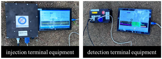
Figure 1.
Signal injection terminal and detection terminal device.
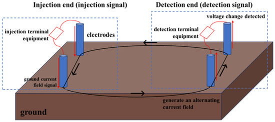
Figure 2.
Horizontal transmission diagram of ground electrode current field signal.
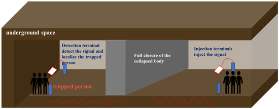
Figure 3.
Practical application scenarios.
The system is composed of several key modules in the hardware design, including the signal injection unit, detection unit, electrode component, and its connecting cable. Figure 1 shows the appearance structure of the injection and detection equipment. The electrodes at the injection end are arranged in a cross arrangement, and two orthogonal injection directions are set. The extremely low-frequency current field signal is injected into the ground through two pairs of electrodes to form a stable ground electrode current field. Compared with the traditional single-electrode design, this two-electrode layout reduces the signal attenuation caused by the poor contact between the electrodes and unreasonable distance, and enhances the signal transmission intensity and uniformity. The detection end electrode adopts the ‘L’-type layout method, and two mutually vertical detection channels are set up to sensitively capture the voltage change of the underground signal. The electrode arrangement shown in Figure 4 clearly shows the relative position of the signal injection end and the signal detection end. All electrodes are buried at a depth of 0.5 m, the electrode spacing at the injection end is 25 m, and the electrode spacing at the detection end is 2 m to improve the accuracy of the voltage signal. Each electrode has a length of 1.2 m and a radius of 0.015 m to ensure a sufficient contact area [26].
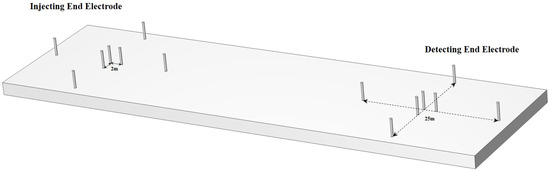
Figure 4.
Schematic diagram of electrode arrangement of injection end and detection end.
In order to enhance the signal transmission capability of the system under complex geological conditions, this study systematically improves the signal type selection, structural parameter tuning, and anti-interference mechanism. First of all, the system selects an extremely low-frequency current field signal with good underground adaptability as the injection source, which shows low attenuation characteristics in the underground medium, and can effectively resist the signal blocking effects caused by structures such as rock strata, sandy soil, and reinforced concrete. The ground current field signal with a total duration of 15 s is injected at the injection end. The first 5 s are the minimum frequency shift keying (MSK) signal for synchronous matching, and the last 10 s are the sine wave signal with a frequency of 10 Hz. The injection voltage is 100 V to ensure that the signal has sufficient propagation energy in complex underground media. The waveform of the injected signal is shown in Figure 5. Secondly, in order to adapt to the conductive characteristics of different underground media, the system dynamically configures the electrode arrangement and injection intensity according to the resistivity distribution of the target area. This mechanism effectively improves the adaptability of the current field structure in the geological non-uniform body and enhances the stability of the signal transmission link.
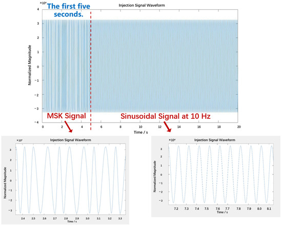
Figure 5.
Injection signal waveform.
In the process of signal transmission, the signal injection end injects the extremely low-frequency current field signal into the underground space through the two electrodes, thus forming the ground electrode current field in the underground medium, and then captures and detects the voltage change of the signal through the three-electrode structure of the detection end, so as to realize the long-distance transmission and efficient signal perception in the underground environment [27,28]. The ground electrode current field signal has a good penetration ability and can propagate across a variety of complex media, which significantly improves the transmission stability and adaptability of the system in the non-ideal underground environment, effectively realizes the long-distance transmission of the signal, and lays a technical foundation for the realization of underground space positioning.
3. Processing of Ground Electrode Current Field Signal
In the actual underground propagation process, the ground electrode current field signal is often affected by factors such as the uneven electrical distribution of underground media, complex geological structure, and frequent electromagnetic interference, and often exhibits strong non-stationarity. Traditional signal-processing methods, such as time domain analysis and frequency domain analysis, have good results in dealing with stationary signals. However, in the face of the nonlinear characteristics of the ground electrode current field signal, it is difficult to effectively extract stable and distinguishable positioning features, which seriously restricts the accurate positioning accuracy based on signal characteristics.
Combined with the characteristics of the ground electrode current field signal, this chapter introduces the FRFT method to perform fractional order transformation on the received signal with the optimal order as the target, to achieve energy concentration and feature enhancement in the optimal fractional domain. By extracting the fractional domain signal characteristics under the optimal order, it provides a more stable and robust signal basis for the subsequent distance modeling and positioning.
3.1. Fractional Fourier Transform
Fourier transform (FT) is a classical time–frequency transform method, which is widely used in the time–frequency analysis of signals. The traditional FT can only transform the signal between the time domain and the frequency domain as a whole, and can not obtain the local time–frequency variation characteristics of the signal. FRFT opens up a new fractional domain between the time domain and the frequency domain, showing all the variation characteristics of the signal from the time domain to the frequency domain, and can extract the local time–frequency variation characteristics of the signal. Its core idea is to map the signal to an optimal fractional domain, where the energy of the non-stationary signal can be more effectively focused [29]. Compared with the traditional Fourier transform which only focuses on the spectrum, FRFT can flexibly capture the essential characteristics of the signal in the ‘time–frequency joint domain’ by adjusting the order parameters, which greatly improves the expression ability of the signal and the stability of feature extraction.
In the time-frequency coordinate system, the Fourier transform is regarded as rotating 90° counterclockwise from the time axis to the frequency axis, and then the FRFT rotates the time domain t-axis counterclockwise to obtain a specific fractional domain u-axis [30], as shown in Figure 6, and then we solve the projection of the t-axis data on the u-axis to obtain the FRFT results of the time data.
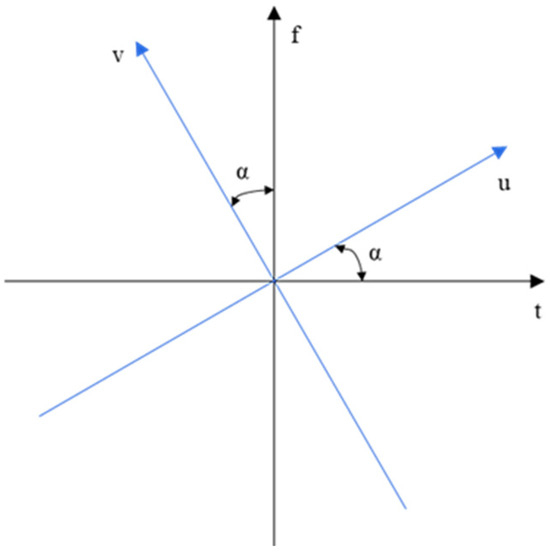
Figure 6.
The time–frequency transform diagram of FRFT.
The input data is x, and its p-order FRFT can be expressed as or ; represents the result of FRFT. On the u domain, is the rotation angle corresponding to the order p, that is, the angle of the new variable u axis turning counterclockwise relative to the time t axis. When p = 1, is the ordinary Fourier transform of x(t); as the order p changes from 0 to 1, FRFT smoothly changes from the original signal to the Fourier transform, so all the characteristics of the signal from the time domain to the frequency domain can be obtained [31].
The p-order FRFT of the signal x(t) is as follows:
where is the kernel function of FRFT, defined as follows:
where is the amplitude factor; n is any integer; and is an impulse function [32].
3.2. Signal Feature Extraction Based on FRFT
In the complex underground environment, the ground electrode current field signal is affected by many factors such as geological structure heterogeneity and electromagnetic interference, showing obvious non-stationarity, which is manifested as the dynamic evolution of the signal characteristics in time and frequency. The traditional time domain and frequency domain analysis methods have the problems of a limited information expression ability and insufficient feature stability when dealing with such non-stationary signals, and it is difficult to effectively extract stable features with a position discrimination ability. Therefore, FRFT is introduced to perform a time–frequency joint analysis of the received signal to achieve the feature enhancement and energy focusing of non-stationary signals.
FRFT can be interpreted as a continuous rotational transform bridging the time and frequency domains. The transformation order α corresponds to the rotation angle θ = α·π/2, and the signal will show different energy distribution patterns at different orders. For a given ground electrode current field detection signal, the energy-focusing degree (such as the energy entropy, maximum amplitude, and second moment) of the signal in the transform domain is optimized by searching in the order interval of 0 to 1, so as to determine the optimal order α* of the signal. The process can be defined as the following optimization objective function:
Here, represents the FRFT result of the signal x(t) under the order α. The signal characteristics, such as the main peak amplitude, main peak frequency, and main peak position, can be extracted by the fractional domain spectrum or power spectrum under the optimal order, which can significantly improve the robustness of the subsequent modeling and positioning.
In order to achieve stable and discriminative feature extraction, the following fractional domain signal-processing flow is adopted in this paper: Firstly, the received signal is band-pass-filtered to suppress environmental interference. Secondly, the coarse step size of 0.1 and the fine step size of 0.01 are set in the range of α ∈ [0, 1], and the optimal fractional order α* of the signal is accurately searched by the two-stage scanning method, that is, the order that can maximize the energy concentration in the fractional order spectrum. Under this optimal order, the amplitude spectrum and power spectrum of the signal in the fractional domain show significant energy-focusing characteristics. The time-domain signal after filtering at the detection end is shown in Figure 7 and Figure 8, which shows the fractional-domain amplitude spectrum of the detection signal under the optimal fractional order. From the graph, it can be seen that the signal exhibits energy concentration characteristics under the optimal order. The results verify the effectiveness of FRFT in dealing with non-stationary signals and can achieve the prominent characterization of key features in the rotation domain.
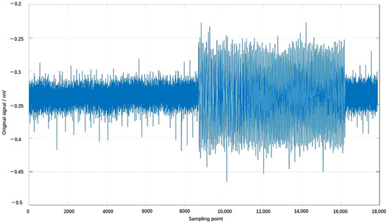
Figure 7.
Time-domain signal after filtering at the detection end.
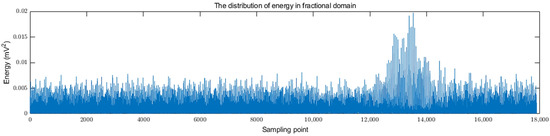
Figure 8.
The fractional domain spectrum of the actual detection signal.
After obtaining the optimal order, the signal is subjected to FRFT transform to extract its multi-dimensional feature parameters in this domain. Nine types of features are extracted, including the main peak amplitude, main peak frequency, power spectrum value corresponding to main peak frequency, half peak width, spectral entropy, energy centroid, skewness, kurtosis, and main peak energy. In the process of feature extraction, by calculating the statistics such as the main peak position and energy centroid of the amplitude spectrum, not only are the distribution characteristics of signal energy in the fractional domain quantified, but the sensitivity to non-stationary changes is also enhanced.
The main peak amplitude and main peak frequency extracted from all measuring point signals constitute two sets of independent feature sets, which correspond to the model (based on the main peak amplitude) and the model (based on the power at the main peak frequency) in the positioning model, respectively, providing stable and robust feature support for the subsequent distance modeling, trilateration, and feature fusion.
4. Signal Feature Location of Ground Electrode Current Field in Fractional Domain
In order to realize the positioning based on the ground electrode current field, this chapter further establishes the mathematical relationship model between the signal characteristics and the transmission distance based on the fractional domain signal characteristics extracted in the previous chapter, and constructs the positioning algorithm on this basis. Considering that the ground electrode current field signal is affected by the electrical distribution of geological media, structural inhomogeneity, and other factors in the process of underground propagation, the signal characteristics and transmission distance often show a complex nonlinear mapping relationship, and it is difficult to directly use the traditional linear or ideal free space model for prediction. In order to improve the modeling accuracy and practical adaptability, this chapter constructs a distance prediction model for two types of fractional domain features based on the main peak amplitude and the power at the main peak frequency, and uses the trilateral measurement principle to design the positioning process. At the same time, the geometric consistency constraint mechanism is introduced to fuse the results of multiple models to improve the robustness and stability of positioning.
4.1. Distance Relation Modeling
When the ground electrode current field signal propagates in the underground medium, its characteristic quantity presents a complex nonlinear law with the change in spatial distance. In order to realize the distance inversion and positioning solution based on signal characteristics, it is necessary to establish a mathematical mapping model between the key fractional domain features of the received signal and the distance between the injection points. Based on the above FRFT feature extraction results, this paper constructs two kinds of empirical modeling methods, which correspond to the main peak amplitude and the power spectrum value at the main peak frequency in the fractional domain spectrum. These two types of features show a strong stability and discriminant ability in actual signals, which can provide effective distance estimation support for the subsequent positioning algorithms.
In view of the fact that FRFT can effectively realize the time–frequency joint analysis and energy-focusing processing of non-stationary signals, this paper applies it to the feature extraction of ground electrode current field signals, so as to obtain the dominant features reflecting the strength and structural differences of signals under different frequency focusing. The first type of model takes the amplitude of the main peak in the fractional domain as the input variable. Because the ground electrode signal is easily affected by the conductivity of the geological medium, the non-uniformity of the geological structure, the geomagnetic interference, and other factors when it propagates underground, the amplitude shows an exponential decay trend with the distance, and a certain logarithmic disturbance term is superimposed. Based on this, this paper constructs an exponential-logarithmic composite model to more accurately describe the nonlinear relationship between the amplitude of the main peak and the distance:
Here, represents the amplitude of the main peak of the ground electrode current field signal at the detection point in the fractional domain, d represents the distance between the detection point and the injection point, and A, B, C, and n are the model parameters to be fitted.
The second type of model takes the power spectrum value corresponding to the main peak frequency in the fractional domain spectrum as the input feature. This feature reflects the concentration degree of the signal energy at the dominant frequency, and has good anti-interference stability. In the process of increasing the distance, this feature usually presents a slow decay law of logarithmic and linear mixing. Based on this, this paper introduces a log-linear mixed term to construct the second type of distance relationship model:
Here, represents the power of the ground electrode current field signal at the detection point at the fractional domain frequency, d represents the distance between the detection point and the injection point, and A, B, C, and n are the model parameters.
The above two models reveal the distance dependence in the signal transmission process from the amplitude characteristics and energy characteristics, respectively, and have complementary advantages. In the subsequent positioning process, this paper will perform distance inversion based on the and models, respectively, and, on this basis, build a fusion positioning algorithm to achieve multi-feature and multi-model geometric consistency optimization positioning.
4.2. Trilateral Positioning Algorithm
Based on the completion of signal feature extraction and the distance estimation model construction, this paper further designs a trilateral positioning framework based on multi-injection point configuration pairs to realize the two-dimensional spatial coordinate solution of the detection points. Trilateration is a positioning method based on geometric constraints. The basic idea is that, when the distance between the detection point and the injection points of three or more known positions is measurable, the plane coordinate position of the detection point can be inversely derived by solving the geometric intersection.
Suppose that there are injection points whose coordinates are , and the distance between the detection point and the injection point is estimated by the characteristic model and the characteristic model , denoted by . In an ideal state, the detection point should satisfy the following geometric constraints:
However, in practical applications, due to the existence of factors such as attenuation, interference, geological inhomogeneity, the multipath effect, and model error in signal transmission, multiple ranging circles often cannot form a unique intersection, but there is an intersection area or offset. Therefore, this paper transforms the localization problem into a nonlinear least squares optimization problem, and constructs the following cost function:
Here, (x,y) are the coordinates of the detection point to be estimated, and is the distance estimated based on the signal characteristics in the fractional domain. By minimizing the objective function, the optimal position estimation result can be obtained.
In order to further improve the positioning accuracy and robustness, a fusion strategy is introduced to integrate the complementary information of the two types of feature models on the basis of trilateral positioning based on the two types of feature models. Considering that the main peak amplitude and the power value at the main peak frequency reflect the different physical characteristics of the signal, that is, the instantaneous amplitude change and energy distribution of the signal, it is complementary to the sensitivity and stability of the spatial position, and the single model has local deviation at some measuring points. Therefore, this paper constructs a fusion model by joint optimization to make the final estimation result as close as possible to the output of the two models, and allows different weights to be applied according to the reliability of the model. The optimization objective function is defined as follows:
Among them, is the fusion coordinate, is the main peak amplitude positioning coordinate, is the power positioning coordinate at the main peak frequency, and and are the weight factors.
In order to further rationally configure the influence degree of different feature models in the fusion process, this paper designs an adaptive weight factor determination mechanism based on the standard deviation of the positioning error, considering that, in a specific experimental area, it is assumed that the real coordinates of several detection points can be obtained, so that the positioning results of the two feature models are, respectively, analyzed with the true values, and the error distribution characteristics are counted.
Let and represent the positioning errors of the two methods on n known measuring points, respectively. The positioning results of the main peak amplitude method and the power method on n test points are and , respectively, and the corresponding real coordinates are . The error sequences of the two methods can be defined as follows:
The error standard deviations corresponding to the two methods are recorded as follows:
Based on the reciprocal ratio principle of error standard deviation, the weight factor is defined as follows:
This mechanism can dynamically adjust the confidence of the model without relying on empirical adjustment, thereby enhancing the robustness and adaptability of the fusion positioning.
5. Positioning Results
In order to verify the feasibility and effectiveness of the fractional domain feature extraction and positioning method of the ground electrode current field signal, this paper builds an experimental system for the injection and detection of the ground electrode current field signal, and carries out multiple sets of positioning experiments in the underground environment. The experimental system is reflected in Figure 1, including the known injection end (signal injection device), the unknown detection end (signal detection device), the connecting wire, and the electrode array. Three groups of known injection ends and a group of unknown detection ends are arranged. The electrode layout of the experimental site and the layout of equipment and electrodes are shown in Figure 4 and Figure 9.
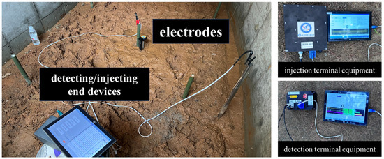
Figure 9.
The electrode layout of the test site and the electrode layout of the injection end and the detection end equipment.
The satellite signal in the selected test site is extremely weak or even unacceptable, and has good electromagnetic shielding characteristics. The spatial structure is composed of concrete walls, steel roofs, and reinforced concrete floors. The local area is filled with gravel and moist soil to simulate the heterogeneous media common in the actual underground environment. The test area also contains infrastructure such as metal pipes and cable ducts, which construct complex signal propagation paths. The overall environment has strong signal attenuation and reflection characteristics, which poses a certain challenge to the proposed positioning method, and also enhances the representativeness and practicability of the experimental results.
Table 1 lists the ambient temperature and formation humidity for each experiment. During the experiment, environmental parameters such as temperature and humidity have natural fluctuations, which may indirectly affect the conductivity of the underground medium and the stability of the signal acquisition of the equipment, thereby causing signal amplitude changes and noise disturbances. Although there are such interference factors, by analyzing the positioning errors under different environmental conditions, it can be seen that the proposed method maintains a high consistency and accuracy in multiple rounds of experiments, and the overall error changes little without a systematic offset. This further verifies that the system has good environmental adaptability and can maintain stable operation in the actual complex medium environment.

Table 1.
Temperature and humidity conditions during the experiment.
As shown in Figure 10, a total of 5 groups of injection points and 6 detection points were set up in this experiment, and 101 sets of geoelectric field response sample data were collected for the subsequent fractional domain feature extraction, distance modeling, and positioning algorithm evaluation.
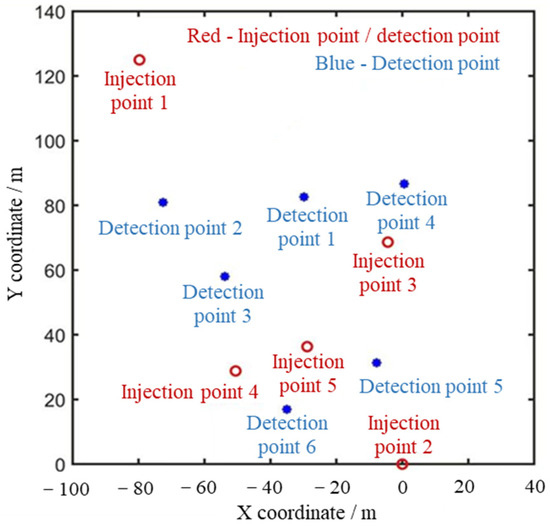
Figure 10.
Position diagram of injection point and detection point.
In order to verify the validity of the established feature–distance model, based on the 38 sets of ground electrode current field response samples collected in the experiment, the nonlinear fitting modeling of the main peak amplitude characteristic model () and the power characteristic model () at the main peak frequency is carried out, and the scatter plot and fitting curve are drawn, as shown in Figure 11. It can be observed that there is a certain monotonic attenuation relationship between the two types of features and the distance, and there is a good fitting trend in most of the distance intervals.
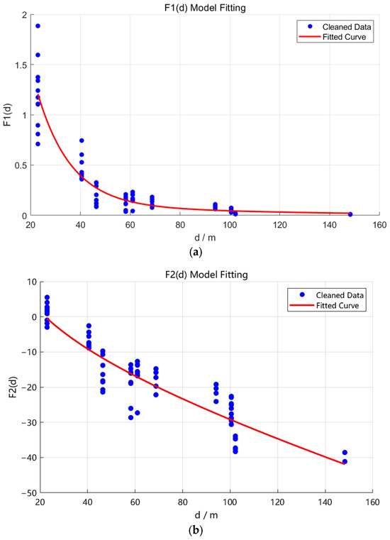
Figure 11.
Fractional domain feature–distance fitting curve: (a) main peak amplitude–distance fitting curve; and (b) power at main frequency–distance fitting curve.
The model parameters are estimated by the least square method, which describe the nonlinear attenuation behavior of the two features in the spatial propagation process. The specific expression is as follows:
Table 2 shows the prediction distance and average error calculated by the two feature–distance models in the experimental area of more than 10,000 square meters, the error of the first behavior model, and the error of the second behavior model:
Table 2.
Estimation error of distance from detection point to injection point (m).
It can be seen from Table 2 that the average error of the model is 5.182 m, the maximum error is 9.869 m, and the minimum error is 0.459 m. The average error of the model is 5.172 m, the maximum error is 9.947 m, and the minimum error is 0.226 m. Further analysis shows that the error mainly comes from the following aspects: Firstly, the signal detected at the detection end is the superposition of the ground electrode current field signal and the environmental noise caused by the equipment and cable. Although the signal is filtered and enhanced, the feature extraction process is still inevitably affected by the residual noise. Secondly, the underground space medium is complex, and the signal may produce reflection and diffraction during transmission, forming a multipath effect, which affects the stability and positioning accuracy of the feature. In addition, the power frequency interference and low-frequency electromagnetic noise that are common in underground power systems and operating equipment will further interfere with signal detection, especially in the low-frequency band. Finally, environmental factors such as temperature, humidity, and medium conductivity will also change the transmission characteristics of the signal. Although there are many error sources mentioned above, the overall positioning error of the system can still be maintained within an acceptable range and show good robustness through the optimization design of signal feature extraction, simulation, and fusion positioning.
Based on the above distance, the trilateral positioning experiment of the ground electrode current field signal is carried out. The distance between each detection point and three selected injection points is calculated by using the main peak amplitude characteristic model and the main frequency power characteristic model, respectively, and the trilateral positioning system under nonlinear geometric constraints is constructed accordingly.
Table 3 and Table 4 summarize the actual coordinates of some detection points, the positioning coordinates estimated by the model and model, and the corresponding errors. It can be seen from the positioning error that the two models have achieved relatively stable spatial positioning at most points. The comprehensive error statistics show that the average error of the model trilateral positioning is 7.53 m, and the model is 8.94 m. The maximum error of the two is less than 10 m, which verifies the feasibility of the distance backstepping method based on the characteristics of the fractional domain signal in the underground space.
Table 3.
model positioning coordinates and errors.
Table 4.
model positioning coordinates and errors.
In order to further improve the positioning accuracy and stability, this paper introduces a fusion positioning strategy under the constraint of feature consistency. On the basis of obtaining the positioning results of the model and the model, the weighted least squares criterion is used for coordinate fusion, and the weight factor is adaptively set according to the error standard deviation of each model in the region, so as to realize the error suppression and credibility enhancement in the single-point positioning results. Compared with the positioning results of the single-feature model, the fusion strategy can effectively balance the complementary advantages of the two and alleviate the instability of the single feature at specific points. The fusion positioning error is shown in Figure 12, and the average error is reduced to 6.896 m, showing a higher stability and accuracy.
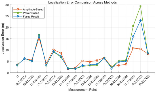
Figure 12.
Fusion positioning and single-feature positioning error.
In addition to the accuracy and robustness, the computational overhead is also an important indicator to measure the engineering adaptability of this method, especially in scenarios with high response time requirements such as emergency rescue. In order to evaluate the real-time performance of the proposed positioning process, this paper conducts a quantitative statistical analysis on the whole process of signal feature extraction, feature–distance modeling, distance inversion, single-feature trilateral positioning, and fusion positioning. The test is carried out on a standard laptop with an Intel Core i9-13980HX 2.20 GHz CPU and 16 GB memory. The FRFT feature extraction process includes filtering, fractional order optimal parameter search, FRFT transform, and feature extraction. The average time consumption is about 0.5 s/channel. In the modeling stage, a nonlinear fitting model is constructed for the main peak amplitude () and the power () at the main peak frequency. Among them, the model adopts the exponential–logarithmic composite expression, and the average fitting time is about 0.3 s, while the more concise model is based on the combination of log(d) and linear terms, and the fitting time is about 0.1 s. For the distance inversion step, the numerical optimization method is used to reverse the eigenvalues of each measuring point. The average inversion time of the feature is about 0.2 s/point, and the feature is 0.06 s/point. In the trilateral positioning stage, the target coordinates are calculated according to the three-point inversion distance, and the average calculation time does not exceed 0.1 s/point. Finally, in the fusion positioning stage, based on the geometric consistency relationship between the two feature positioning results, the weighted average method based on cosine consistency is used for fusion, and the average calculation time is about 0.5 s/point. In summary, it takes less than 5 s to complete a complete feature extraction, model construction, distance inversion, and fusion positioning process, which has good real-time performance. It shows that the proposed method has certain engineering deployment potential, and is especially suitable for emergency positioning tasks with the dual requirements of accuracy and response speed in an underground environment.
6. Conclusions
Aiming at the problem of the lack of positioning satellites and no available beacons in underground space, this paper proposes an autonomous positioning method based on injected ground electrode current field signals, and introduces FRFT to extract the features of strong non-stationary ground electrode current field signals. By constructing a nonlinear feature–distance mapping model, combined with the trilateral positioning algorithm and multi-feature fusion mechanism, the two-dimensional position solution in the complex underground environment is realized. The experimental results show that the technical route is feasible, and the distance information can be effectively obtained according to this method. The precise positioning of any position in the positioning area can be realized by using multi-feature fusion trilateral positioning, and the single-point positioning accuracy can reach 1.745 m.
The signal of the injected ground electrode current field has a good low-frequency penetration ability and can be transmitted in media such as soil and rock. Therefore, the positioning method based on this mechanism has the advantages of natural environmental adaptability and no auxiliary dependence. This method does not rely on external infrastructure or wireless signal support, and can complete location settlement in extreme environments such as a lack of satellites, no available beacons, and no communication networks. It is especially suitable for emergency positioning and space management in complex scenes such as underground mines, tunnels, subway corridors, and disaster collapses.
It should be emphasized that the method in this paper is a preliminary study, and the purpose is to explore the application of ground current field signals in underground space positioning. Although the research on the ground current field has been gradually carried out, its application in underground positioning is still in a relatively preliminary stage. In the future, the research will focus on exploring the realization of the three-dimensional positioning capability: (1) In terms of the electrode layout, we plan to add vertical electrode pairs to the existing electrode layout, and construct a three-dimensional current field injection and detection array to sense the signal attenuation in the height (depth) dimension; (2) in terms of the algorithm, a three-dimensional spatial feature extraction method based on FRFT will be developed, and a nonlinear feature–distance mapping model including depth variables will be constructed; (3) in terms of the positioning solution, the research will integrate multi-plane measurement data or adopt the principle of spatial spherical intersection positioning, combined with the multi-source feature fusion strategy, and finally realize the joint solution of the target point (x, y, z) coordinates; and (4) in terms of the positioning range expansion, the research will gradually expand the spatial scale of the experimental site, from the current small scale to a larger scale, and adjust and optimize the feature model and positioning algorithm in combination with different and more complex geological conditions, so as to improve the universality of the method, the accuracy of positioning, and the engineering adaptability. The above research ideas are expected to gradually realize the three-dimensional positioning ability of underground space, and will become an important direction for the subsequent expansion of this method.
Author Contributions
Conceptualization, S.C., H.Z. and Z.S.; methodology, S.C., H.Z. and Z.S.; software, S.C.; validation, S.C.; formal analysis, S.C.; investigation, S.C., Y.W., Z.L., H.Z. and X.Y.; resources, Z.S. and H.Z.; data curation, S.C., Y.W., H.Z. and Z.L.; writing—original draft preparation, S.C.; writing—review and editing, S.C., Z.S., X.Y., H.Z. and X.G.; supervision, Z.S. and H.Z.; project administration, Z.S.; funding acquisition, Z.S. All authors have read and agreed to the published version of the manuscript.
Funding
This study was supported by the National Natural Science Foundation of China (61971048), and the Beijing Natural Science Foundation (4244091).
Data Availability Statement
The data presented in this study are available in the article.
Acknowledgments
The authors want to thank the Key Laboratory of Modern Measurement and Control Technology of the Ministry of Education, and the Beijing Key Laboratory of High Dynamic Navigation Technology for their assistance.
Conflicts of Interest
The authors declare no conflicts of interest.
Abbreviations
The following abbreviations are used in this manuscript:
| FRFT | fractional Fourier transform |
References
- Michael, R.; Gerald, T.; Nicholas, W.; Justin, R. NIOSH-Sponsored Research in Through-the-Earth Communications for Mines: A Status Report. IEEE Trans. Ind. Appl. 2012, 45, 1700–1707. [Google Scholar]
- Wang, G.; Zhao, X.; Yang, C.; Ma, L.; Dai, W. Recent advances in research on underground space positioning technology for coal mining. Chin. J. Eng. 2024, 46, 1713–1727. [Google Scholar]
- Dehghan Firoozabadi, A.; Azurdia-Meza, C.; Soto, I.; Seguel, F.; Krommenacker, N.; Iturralde, D.; Charpentier, P.; Zabala-Blanco, D. A Novel Frequency Domain Visible Light Communication (VLC) Three-Dimensional Trilateration System for Localization in Underground Mining. Appl. Sci. 2019, 9, 1488. [Google Scholar] [CrossRef]
- Jordaan, J.; Kruger, C.; Silva, B.; Hancke, G. An ultrasonic-based localization system for underground mines. In Proceedings of the 2017 IEEE 15th International Conference on Industrial Informatics (INDIN), Emden, Germany, 24–26 July 2017; p. 141. [Google Scholar]
- Xu, Z.; Yang, W.; You, K.; Li, W.; Kin, Y. Vehicle autonomous localization in local area of coal mine tunnel based on vision sensors and ultrasonic sensors. PLoS ONE 2017, 12, e171012. [Google Scholar] [CrossRef]
- Sun, M.; Wang, Y.; Huang, L.; Xu, S.; Cao, H.; Joseph, W.; Plets, D. Simultaneous WiFi ranging compensation and localization for indoor NLoS environments. IEEE Commun. Lett. 2022, 26, 2052. [Google Scholar] [CrossRef]
- Lin, C.; Chen, L.; Wu, H.; Jin, M.; Chen, G.; Gomez, J.; Chou, C. An indoor positioning algorithm based on fingerprint and mobility prediction in RSS fluctuation-prone WLANs. IEEE Trans. Syst. Man Cybern. Syst. 2021, 51, 2926. [Google Scholar] [CrossRef]
- Kianfar, A.; Uth, F.; Baltes, R.; Clausen, E. Development of a robust ultra-wideband module for underground positioning and collision avoidance. Min. Metall. Explor. 2020, 37, 1821. [Google Scholar] [CrossRef]
- Wang, S.; Wang, S.; Liu, W.; Tian, Y. A study on the optimization nodes arrangement in UWB localization. Measurement 2020, 163, 108056. [Google Scholar] [CrossRef]
- Sa, Y.; Zhu, Z.; Shen, G.; Li, X.; Tang, Y.; Chen, P.; Wang, Q. NLOS mitigation algorithm by distance geometric constrain for mine-used underground monorail crane localization. IEEE Trans. Instrum. Meas. 2023, 72, 1. [Google Scholar] [CrossRef]
- Liu, G.; Shi, L. Review on the development of indoor navigation and positioning technology. J. Navig. Position 2018, 6, 7. [Google Scholar]
- Abrudan, T.; Xiao, Z.; Markham, A.; Trigoni, N. Underground incrementally deployed magneto-inductive 3-D positioning network. IEEE Trans. Geosci. Remote Sens. 2016, 54, 4376. [Google Scholar] [CrossRef]
- Wang, H.; Hao, M.; Zhuang, W. Application of GNSS real-time satellites clock offset estimation in seismic monitoring. Nav. Position. Timing 2023, 10, 108. [Google Scholar]
- Song, M.; Qian, J. Underground Coal Mine Fingerprint Positioning Based on the MA-VAP Method. Sensors 2020, 20, 5401. [Google Scholar] [CrossRef]
- Xu, Z.; Wen, X.; Zhang, G. Path Loss Modeling and Analysis Based on Extremely Low Frequency Current Field Through-the-earth Communications. Telecommun. Eng. 2024, 64, 376–381. (In Chinese) [Google Scholar]
- Xu, Z.; Zhang, X.; Yang, X. Two-stage Long-correlation Signal Acquisition Method for Through-the-earth Communication of the Ground Electrode Current Field. J. Electron. Inf. Technol. 2024, 46, 4504–4512. [Google Scholar]
- Damiano, N.W.; Yan, L.; Whisner, B.; Zhou, C. Simulation and Measurement of Through-the-Earth, Extremely Low-Frequency Signals Using Copper-Clad Steel Ground Rods. IEEE Trans. Ind. Appl. 2017, 53, 5088–5095. [Google Scholar] [CrossRef]
- Su, Z.; Chen, J.; Xu, Z.; Liu, N.; Li, L. A TTE-LAN Communication Scheme for Tunnel Rescuing. J. Phys. Conf. Ser. 2019, 1213, 052071. [Google Scholar] [CrossRef]
- Farnaz, P.; Rashidi, S.; Sheikhani, A. Application of fractional Fourier transform in feature extraction from ELECTROCARDIOGRAM and GALVANIC SKIN RESPONSE for emotion recognition. Biomed. Signal Process. Control 2021, 69, 102863. [Google Scholar]
- Mei, J.; Ren, G.; Chang, C. Multiple information fusion based on single component feature and diagnosis of gear’s early fault. Vibroeng. Procedia 2018, 18, 52–56. [Google Scholar] [CrossRef][Green Version]
- Bajaj, A.; Kumar, S. QRS complex detection using fractional Stockwell transform and fractional Stockwell Shannon energy. Biomed. Signal Process. Control 2019, 54, 101628. [Google Scholar] [CrossRef]
- Bajaj, A.; Kumar, S. A robust approach to denoise ECG signals based on fractional Stockwell transform. Biomed. Signal Process. Control 2020, 62, 102090. [Google Scholar] [CrossRef]
- Keshishzadeh, S.; Fallah, A.; Rashidi, S. Electroencephalogram Based Biometrics: A Fractional Fourier Transform Approach. In Proceedings of the 2018 2nd International Conference on Biometric Engineering and Applications, New York, NY, USA, 16–18 May 2018; pp. 1–5. [Google Scholar]
- Du, X.; Wen, G.; Liu, D.; Chen, X.; Zhang, Y.; Luo, J. Fractional iterative variational mode decomposition and its application in fault diagnosis of rotating machinery. Meas. Sci. Technol. 2019, 30, 125009. [Google Scholar] [CrossRef]
- Jia, Y.; Li, F.; Tao, J.; Wang, P. Transmission Characteristics of Very Low Frequency Electromagnetic Wave of Mine-Seam Wireless Through-the-Earth Communication System. Ind. Mine Autom. 2015, 41, 31–33. [Google Scholar]
- Chu, S.; Zhao, H.; Su, Z.; Yao, X.; Gu, X.; Wang, Y.; Ling, Z. Research on Centroid Localization Method of Underground Space Ground Electrode Current Field Based on RSSI. Sensors 2025, 25, 2889. [Google Scholar] [CrossRef]
- Zhang, G.; Xu, Z.; Chen, J.; Wen, X. OFDM Signal Design Based on Electrode-based Through-the-earth Communication. In Proceedings of the 2021 20th International Conference on Ubiquitous Computing and Communications (IUCC/CIT/DSCI/SmartCNS), London, UK, 20–22 December 2021; pp. 40–45. [Google Scholar]
- Ngwenyama, P.L.; Webber-Youngman, R.C. A Review of the Applications of Through-the-Earth (TTE) Communication Systems for Underground Mines. Min. Metall. Explor. 2024, 41, 2291–2323. [Google Scholar] [CrossRef]
- Fan, H.; Huang, J.; Ren, Z.; Xu, H. Filtering based on FRFT for extracting fault orders of sun gears in a variable speed planetary gear system. J. Mech. Transm. 2025, 49, 127–138. [Google Scholar]
- Tao, R.; Deng, B.; Zhang, W.; Wang, X. Sampling and Sampling Rate Conversion of Band Limited Signals in the Fractional Fourier Transform Domain. IEEE Trans. Signal Process. 2008, 56, 158–171. [Google Scholar] [CrossRef]
- Meng, Z.; Bai, R.; Xu, Q.; Li, J.; Fan, F. Fractional Fourier Domain Feature Fusion Combining Multichannel Targeting Extreme Learning Machine for Bearing Fault Diagnosis. IEEE Trans. Instrum. Meas. 2023, 72, 1–13. [Google Scholar] [CrossRef]
- Shang, M.; Xu, X. Chirp scaling algorithm based on fractional Fourier transform and image weighted entropy. J. Univ. Chin. Acad. Sci. 2024, 41, 644–653. [Google Scholar]


Disclaimer/Publisher’s Note: The statements, opinions and data contained in all publications are solely those of the individual author(s) and contributor(s) and not of MDPI and/or the editor(s). MDPI and/or the editor(s) disclaim responsibility for any injury to people or property resulting from any ideas, methods, instructions or products referred to in the content. |
© 2025 by the authors. Licensee MDPI, Basel, Switzerland. This article is an open access article distributed under the terms and conditions of the Creative Commons Attribution (CC BY) license (https://creativecommons.org/licenses/by/4.0/).