1. Introduction
Since the early 2000s, Orthogonal Frequency Division Multiplexing (OFDM) has emerged as the dominant strategy for designing the physical layer of contemporary communication systems. Its widespread adoption stems from the ability to divide the available frequency spectrum into narrowband subchannels (also called subcarriers) using the Discrete Fourier Transform (DFT). With appropriately chosen modulation parameters, transmissions on these subchannels remain orthogonal across consecutive OFDM symbols [
1].
This orthogonality enables the application of classical equalization techniques such as Zero Forcing (ZF) and Minimum Mean Square Error (MMSE) [
2,
3], because each subchannel can be independently equalized. However, the performance of these equalization methods depends heavily on the accuracy of the estimated channel response.
A common method for channel estimation is the Least Squares (LS) technique [
4], which estimates each subchannel’s frequency response as the ratio of transmitted to received pilot symbols. Although straightforward and computationally light, LS estimation is sensitive to noise, leading to high variance in the estimates. To address this, more advanced techniques like Linear Minimum Mean Square Error (LMMSE) estimation have been proposed [
5,
6,
7], which leverage statistical information about the channel at the cost of increased computational complexity.
In recent years, alternative channel estimation approaches based on compressive sensing (CS) and deep learning (DL) have gained significant attention in the context of OFDM systems. CS techniques exploit the sparsity of the channel impulse response in the delay domain and use algorithms such as Orthogonal Matching Pursuit (OMP) or basis pursuit for reconstruction [
8,
9]. Similarly, DL-based methods leverage neural networks trained on large datasets to map received signals to channel estimates [
10,
11,
12,
13]. While these approaches have shown promising results—especially in dynamic or nonlinear channels—they typically require substantial computational resources, access to labeled training data, as well as prior knowledge about the channel’s statistical properties. In contrast, the method proposed in this paper is designed to be statistically agnostic, computationally lightweight, and readily deployable in real-time and resource-constrained OFDM systems.
An alternative yet computationally efficient method—defined here as one that reduces the number of multiplications using matrix-based operations—employs a DFT-based approach, which begins with a simple least squares (LS) estimate of the channel frequency response (CFR) [
14]. This approach assumes that the channel impulse response (CIR), recovered through an N-point Inverse DFT (IDFT), is confined within the guard interval (GI). Taps outside the GI are treated as noise and are suppressed using a rectangular window. The denoised CIR is then transformed back to the frequency domain. Numerous variations of this method have been proposed in the literature [
15,
16,
17,
18,
19,
20].
In practical OFDM systems, null subcarriers with no signal transmission—typically placed at the spectrum edges—are introduced to suppress out-of-band interference. This structure is common in standards such as Digital Video Broadcasting (DVB) [
21], Wireless Fidelity (WiFi) [
22], and Long Term Evolution (LTE)/5G [
23,
24]. However, these inactive subcarriers disrupt the orthogonality of the DFT, which leads to energy leakage in the reconstructed CIR, thereby degrading channel estimation accuracy [
25].
One way to mitigate this effect is to reduce energy leakage in the CIR and then select the most significant taps. This is typically achieved by minimizing the discontinuity between active and null subcarriers in the CFR [
23,
26,
27,
28,
29,
30,
31]. Another effective approach focuses solely on active subcarriers, completely excluding the null subcarriers from analysis. This corresponds to null extrapolation in the DFT-based approach; however, rather than explicitly applying IDFT and DFT, the method minimizes the squared error of pilot CFR values [
32]. In this approach, the LS estimate is refined by multiplying it with a precomputed square matrix derived from a reduced DFT matrix. This matrix includes only the active subcarriers and taps within the channel delay spread, and its dimensions match the number of active subcarriers.
This paper builds upon and extends the method introduced in [
32]. First, it derives the threshold number of active subcarriers beyond which a Fast Fourier Transform (FFT)-based implementation becomes more computationally efficient due to a reduced number of multiplication operations. Next, the paper explores alternative distributions of null subcarriers beyond the conventional placement at spectral edges. This is especially relevant for future cognitive radio systems that aim to utilize non-contiguous spectrum segments [
33,
34,
35]. To avoid storing multiple precomputed matrices for varying channel delays, we propose a method that identifies the energy-dominant region of the CIR and applies a circular shift accordingly. The focus on LS estimation and active subcarriers is driven by the aim to provide a universal, practical solution that circumvents the need for statistical modeling of the channel response and extrapolation to unused subcarriers. Furthermore, the proposed method is evaluated under conditions of fractional tap delays, which introduce additional CIR leakage effects.
The remainder of the paper is organized as follows.
Section 2 presents a model of the OFDM transmission system with the basic LS channel estimation procedure, which is the initial point of the method presented in
Section 3. This section offers a mathematical formulation of the investigated method, accompanied by an analysis of its implementation complexity in terms of multiplication operations.
Section 4 discusses the simulation scenarios for OFDM transmission and introduces a correction procedure to preserve the precomputed matrix coefficients, even in the presence of symbol synchronization fluctuations. Finally, the results of the numerical experiments are presented, illustrating the system’s performance in terms of Bit Error Rate (BER) and Mean Squared Error (MSE) metrics and including a comparison with related methods.
Notation: Matrices and vectors are denoted using boldface (e.g., or ) and blackboard bold (e.g., ) fonts. Their elements are indexed by italic lowercase letters in parentheses (e.g., ). A superscript in parentheses denotes the current iteration number. The symbols ,, , ∘ and denote the transpose, the conjugate transpose, squared L2-norm, Hadamard product and estimated value, respectively. Italic uppercase and lowercase letters denote signal variables in the frequency and time domain, respectively. Their particular frequency or time moments are described in parentheses (e.g., , ). This font style is also used to represent system parameters (e.g., L, N, M, etc.). To prevent ambiguity, the text clearly specifies whether each variable refers to a signal or a system parameter.
2. System Model
The transmission of a signal within selected frequency bands is a characteristic feature of emerging wireless cognitive systems. OFDM modulation naturally aligns with this requirement. Consider a set of N possible subcarriers, where N denotes the size of the DFT in an OFDM implementation. Information is transmitted only on a subset of A active subcarriers, where . QAM coding schemes are employed to encode the data on these active subcarriers. The remaining subcarriers are excluded from transmission and are termed null subcarriers, as they carry no signal. These null subcarriers can be located anywhere within the OFDM signal bandwidth, enabling adaptation of the spectral profile of the transmitted signal to match current transmission conditions or system requirements.
In the time domain, a single OFDM symbol consists of
N samples obtained via an N-point IDFT along with
L samples forming the cyclic prefix (CP) in the guard interval (GI), positioned between the information parts of the consecutive symbols. To prevent intersymbol inteference, the maximum channel delay spread, denoted as
M, is constrained such that
. The frame structure, depicted in
Figure 1, comprises
F consecutive OFDM symbols preceded by a channel estimation training symbol and a synchronization preamble. The training symbol typically employs Quadrature Phase Shift Keying (QPSK) or Binary Phase Shift Keying (BPSK) symbols and follows block-type structure, in which all active subcarriers transmit a known signal pattern to the receiver. For simplicity, the QPSK (BPSK) constellation symbols are assumed to have unit amplitude.
The output signal of the transmitter, denoted by
, propagates through a wireless channel characterized by a multipath response
and is further corrupted by Additive White Gaussian Noise (AWGN)
. Following time and frequency synchronization at the receiver, the cyclic prefix is removed from each OFDM symbol. The remaining
N samples are then processed via an
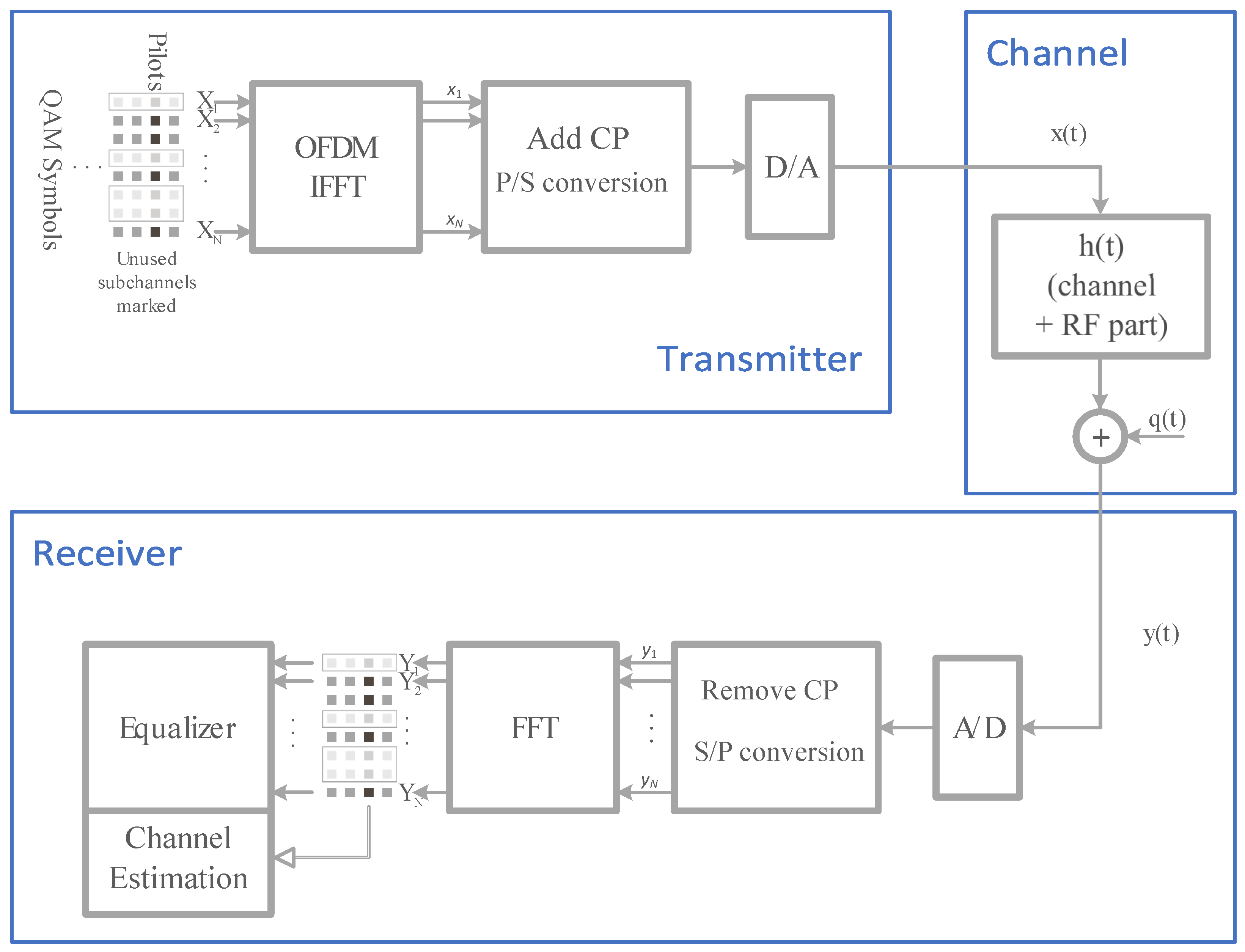
N-point DFT transformation to extract complex symbols corresponding to the active subcarriers. These complex symbols carry either pilot or data information, depending on the type of OFDM symbol. The received pilot symbols are used for channel reconstruction in the Channel Estimation block, and the resulting channel estimate is subsequently applied in the Equalizer block to recover the transmitted information signal. Since the transmission is performed in the baseband, all signals in this system model shown in
Figure 2 are represented as complex-valued waveforms, and every block in the processing chain operates on these complex signals.
The primary objectives of this research are to analyze the complexity of the channel estimation algorithm and to evaluate transmission quality in the presence of a symbol synchronization procedure. Frequency synchronization is assumed to be perfect. Additionally, the transmission channel is considered quasi-static, meaning its characteristics remain constant throughout the transmission of a single frame. This assumption ensures the subchannels orthogonality of each OFDM symbol and permits their independent processing.
Given these assumptions, OFDM transmission can be conveniently represented using matrix notation. In the frequency domain, the reception of
A pilot symbols is described by the vector:
where
is an
diagonal matrix composed of QPSK (BPSK) symbols from the vector
. The subscript
p denotes the signal vector or matrix representing the pilot data transmission. In the case of unit-amplitude, constant-envelope constellations, the following condition is satisfied:
is the CFR vector, representing the impact of the transmission channel on each active subcarrier. denotes the noise vector, accounting for the additive noise present in the system. Both vectors have size where the indices of the active subcarriers belong to the set .
The most straightforward estimation of the CFR on the active subchannels is described as follows:
where
denotes the estimated CFR vector with elements
. The primary limitation of the solution presented in (
4) lies in its inability to effectively mitigate the influence of channel noise
. The next section presents a detailed derivation of a numerically efficient algorithm for estimating the CFR on selected subcarriers, specifically designed to reduce the impact of noise.
3. DFT-Based CFR Estimation Algorithm
3.1. Problem Formulation
Under perfect synchronization, the full-length CIR in the time domain can be described as follows:
where vectors
and
represent the
M first taps of the channel impulse response and the zero vector of appropriate length, respectively. The corresponding
N-point CFR is determined as:
where the square matrix
represents the
N-point DFT. Since the last
taps of the CIR are zero, Equation (
6) can be reformulated as:
where
is a reduced DFT matrix consisting of the first
M columns of the full
N-point DFT. In general, the column indices of the reduced DFT matrix correspond to the positions of the non-zero taps in the CIR, all of which are elements of the set
. Therefore, when permissible synchronization errors occur during the reception of OFDM symbols, the CIR described in (
5) undergoes cyclic shifts consistent with the properties of the DFT. Despite this shift, the associated transformations remain valid, though they involve a modified index set
.
The truncated CIR vector
can be extracted from the full-length CIR vector
using a time domain masking matrix
as follows:
where
is the masking matrix in which each column contains a single element equal to one, corresponding to a non-zero position in the CIR vector
. All remaining columns are zero valued. Using the time domain masking matrix
, Equation (
7) can be reformulated as:
To restrict the CFR vector to the range of active subcarriers defined by the set
, a frequency domain masking matrix of the following form is employed:
in which each column of the frequency mask contains a single element with unit value, corresponding to an active subcarrier indexed in the set
. The CFR of active subchannels can be determined as a
vector:
and consequently substituting (
10) and (
12) into (
1), the received pilots can be expressed as:
Using the LS estimation procedure, the complete solution for the reconstructed CIR can be expressed as follows:
The expression can be simplified by applying appropriate transformations, substituting with Equations (
3) and (
4), while omitting matrix dimensions for clarity. The final form of the CIR estimate is given by:
and the CFR estimate can be calculated as follows:
Equation (
16) can be reformulated into the following compact matrix form:
where
is a Correction Matrix in Frequency (CMF) domain of size
, used to refine the initial CFR estimate
.
Assuming the positions of the CIR taps and the frequency mask are known, can be precomputed, and complex multiplications are required to determine using matrix multiplication operation.
Even if the matrix is not known in advance (due to synchronization uncertainties or changes in the frequency mask structure), various strategies can be employed to obtain it on a device with limited computational resources. For example, the matrix can be transmitted via an auxiliary communication channel from a network node or pre-stored in local device memory in multiple versions. The latter approach, involving shifted versions of the time domain mask, is discussed in a subsequent section.
3.2. Complexity Evaluation of the FFT-Based Approach
Rather than performing the direct matrix multiplication in (
17), the computation in (
16) can be decomposed into three sequential stages. This structured approach facilitates a reduction in computational complexity.
3.2.1. Stage 1
In the first stage of the CFR improvement, the following computation is performed:
This operation corresponds to an N-point IFFT of the full-length CFR, where the reconstructed channel is initially approximated using (
4) on the active subcarriers, while inactive subcarriers are assigned zero values. The resulting intermediate vector
represents a noisy approximation of the CIR additionally degraded by the absence of channel information on the inactive subcarriers.
From a complexity perspective, the implementation of the IFFT procedure using the Radix-2 algorithm typically requires complex multiplications. Since some of the subcarriers are zero valued, the actual number of multiplications can be further reduced.
3.2.2. Stage 2
The second stage is described by the following matrix operation:
This operation is performed entirely in the time domain. The intermediate vector
undergoes an averaging process controlled by the matrix
of the size
, which is determined by the time and frequency masks. Due to the specific structure of the matrix
, which redistributes the averaging results across the CIR taps indexed in the set
, the computational cost of (
20) is reduced to
complex multiplications.
The Correction Matrix in Time (CMT) domain, , can be precomputed in advance, in a manner similar to .
3.2.3. Stage 3
The final stage is defined by the following operation:
This step corresponds to N-point FFT, which typically requires complex multiplications. Similar to Stage 1, the computational load can be further reduced due to the sparsity of the involved vectors: specifically, coefficients of the vector and the coefficients of the vector are zero.
3.3. Complexity Discussion
Table 1 presents the total number of complex multiplications required for both the direct and FFT-based implementation of (
16). From this, the minimum number of active subcarriers, denoted as
, beyond which the use of the CMT matrix becomes more efficient in terms of numerical complexity, can be expressed as follows:
It follows that, for shorter channel delay spreads
M, the CMT matrix approach can be advantageously employed with a lower number of active subcarriers
in the channel estimation process for OFDM modulation. The absolute lower bound is given by
Moreover, the value of
is bounded by the condition
, which is essential for ensuring correct operation of the OFDM system.
Table 2 provides the minimum value of subcarriers
for
N as a power of 2 and for different delay spread length
, given as the fraction of
N. The last column in the table corresponds to
.
Assuming that a complexity reference level (100%) belongs to the direct application of the CMF matrix, the computational complexity reduction in the CMT approach can be defined by the following ratio:
The value
is inversely proportional to the square of the number of pilot subcarriers and proportional to the square of the size of the maximum channel delay spread, scaled by a constant factor dependent on the value of
N. As the size
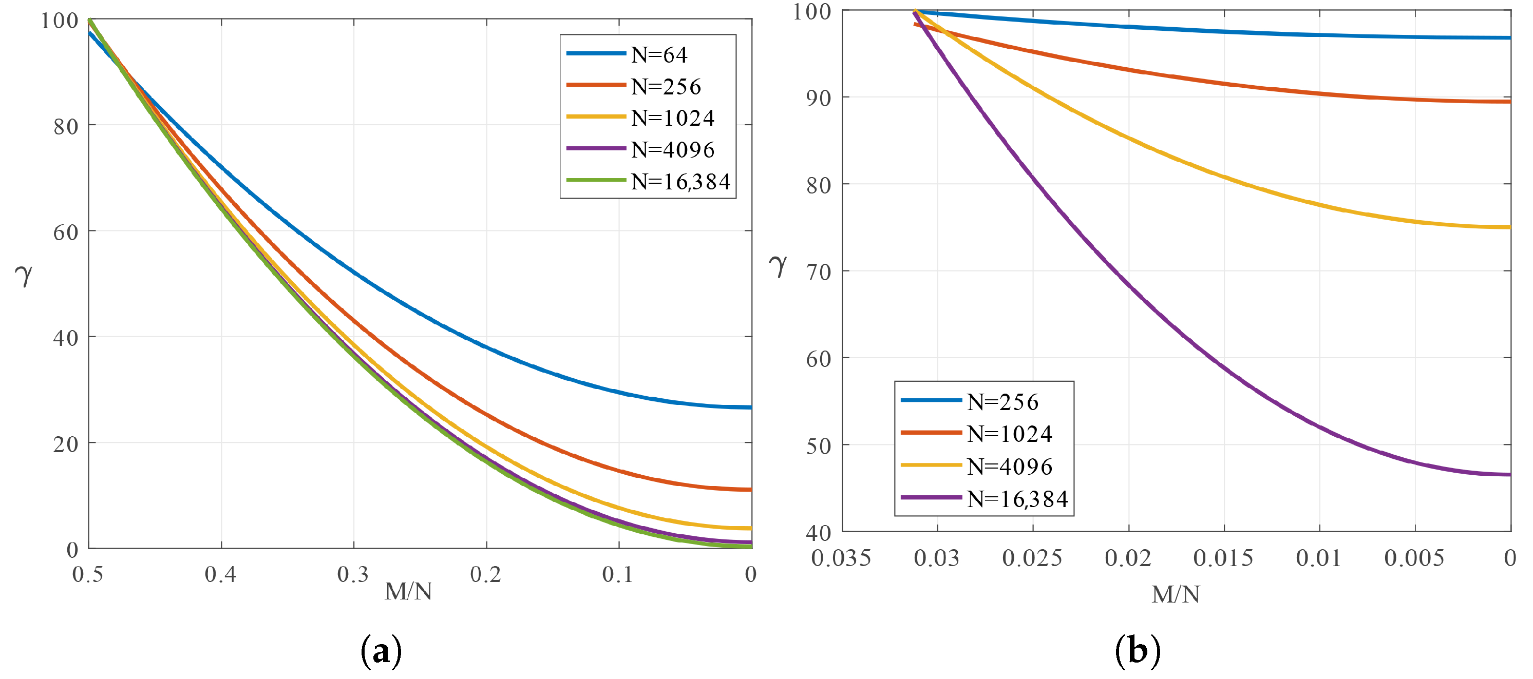
N of the OFDM modulation increases, the computational complexity decreases more significantly for shorter CIR delay spreads. This trend is illustrated in
Figure 3, which compares the behaviour of
for two scenarios:
and
. In the latter case, the efficiency gains are notably less substantial.
Looking at
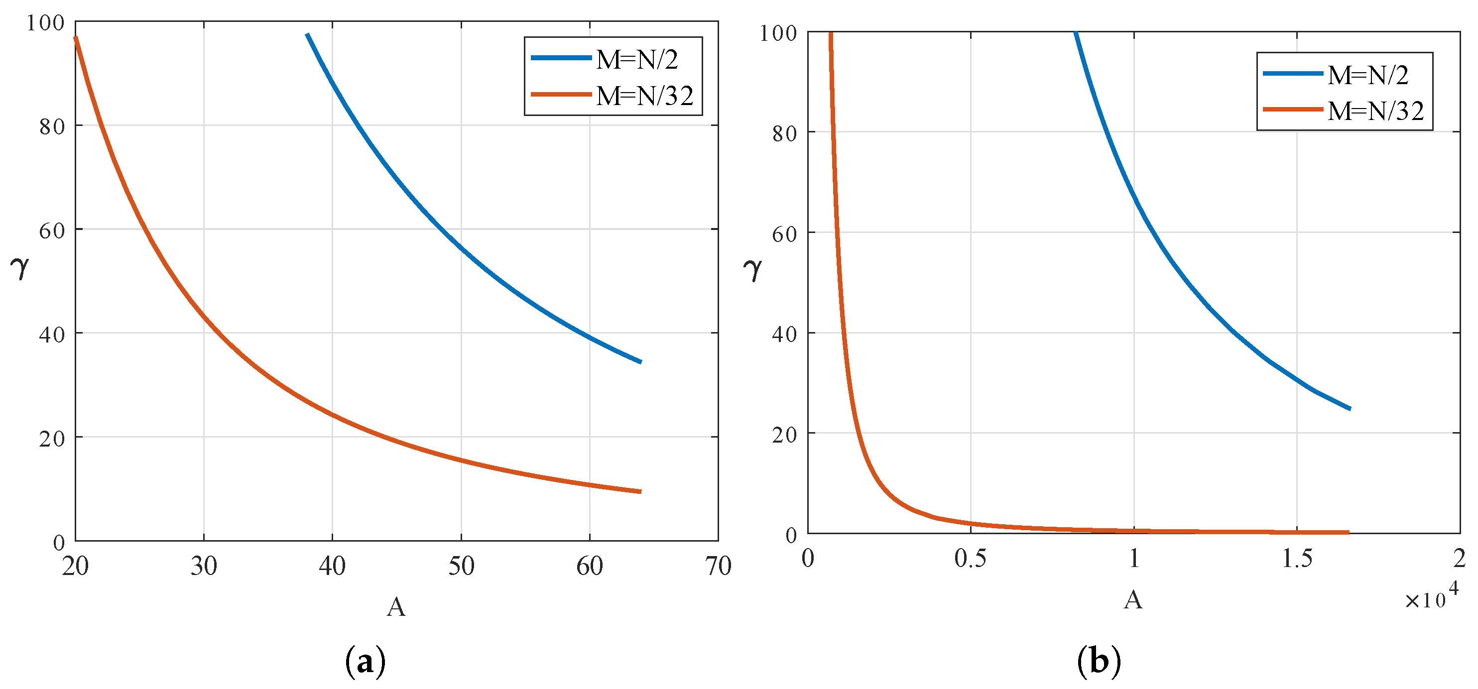
from another perspective, as shown in
Figure 4, as the CIR becomes shorter, the complexity reduction becomes more dynamic with an increasing number of pilot subcarriers. Furthermore, with fewer pilots, it is possible to achieve the same
value (and even smaller) as those attainable under longer channel delay spreads.
The above analysis suggests that the primary beneficiaries of the complexity reduction approach can be fixed and low mobility wireless systems (e.g., broadcasting systems) are characterized by long OFDM symbols and relatively short guard periods. The latter condition is typically found in indoor environments, urban microcell environments with Line of Sight (LoS), and in suburban and rural areas with few buildings or other obstructions. These environments, characterized by minimal multipath effects and short channel delay spread, are well suited to the requirements for effective implementation of the FFT-based approach.
To gain a more detailed insight into the practical aspects, consider as an example a WiFi system compliant with the 802.11 specification [
36], where an L-LTF (Legacy-Long Training Field) signal is employed for the initial channel estimation. The signal comprises two OFDM symbols, preceded by a guard interval of duration equal to half the symbol duration. For a bandwidth of 20 MHz, the number of active pilots in the symbol is 52, and this is doubled for a bandwidth of 40 MHz.
Table 3 illustrates numerical performance in terms of complex multiplications for the most computationally demanding case, namely,
. The last column represents the performance expressed as the ratio of multiplications required in the FFT-based approach relative to the direct implementation of the matrix
.
4. Numerical Experiments
The channel reconstruction performance was evaluated in the OFDM system model using three different frequency masks. Each mask was used in an identical manner to all types of signals transmitted over the channel, including synchronization preamble, training sequence, and data symbols.
The frequency masks modify the original impulse response of the channel, resulting in the CIR dispersion that is consistent with the specific impulse response of the mask. It complicates the localization of the impulse response region that carries the majority of the signal energy. Furthermore, inaccuracies in synchronization result in the time mask, associated with the significant coefficients of the channel impulse response, shifting its position. Consequently, various forms of CMF or CMT matrices would have to be used in the channel reconstruction. These matrix variants could either be computed dynamically or pre-stored in memory.
The solution presented in this paper uses the cyclic shift property, which is inherently compatible with OFDM systems employing a cyclic prefix. This approach ensures that the time mask remains in a fixed location, thereby requiring only a single precomputed matrix (CMF or CMT) for channel estimation. Instead, the frequency characteristics of the processed data—including both pilots and information—are modified according to the principles of the cyclic shift theorem.
4.1. Simulation Scenarios
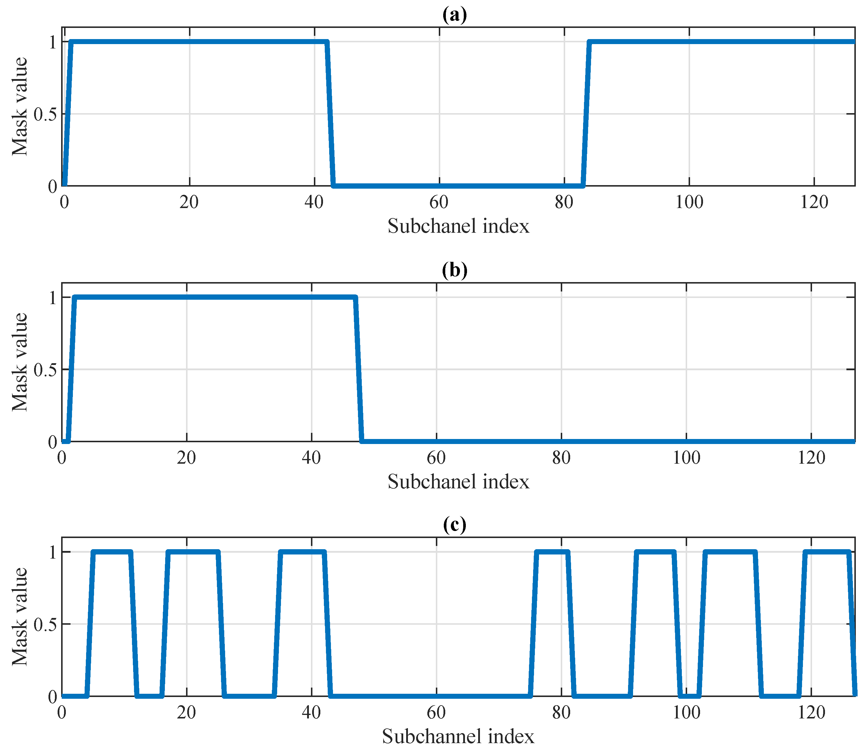
The study proposes three illustrative examples of the frequency masks to demonstrate the potential transmission options. The first, Mask A, represents the classical approach, in which the edge subcarriers (centrally located in the baseband subcarrier index range) and the DC component are excluded from transmission. The second variant, Mask B, depicts a scenario in which only half of the bandwidth is used for transmission. The third, Mask C, exemplifies a situation where the available transmission bands are distributed across the entire OFDM bandwidth. All frequency mask variants are shown in
Figure 5.
The structure of the transmitted signal is as follows: a single transmission over a given channel impulse response comprises 50 frames, each transmitting 50 OFDM symbols containing user data. Each OFDM symbol consists of 128 samples and is preceded by a cyclic prefix of 32, 16, or 8 samples, respectively. A 16-QAM constellation is employed for the active subcarriers in the data symbols. The data symbols are preceded in each frame by one OFDM training symbol of the same length, which transmits QPSK-modulated pilot symbols on the active subcarriers for channel reconstruction. Preceding the training symbol is a synchronization preamble with strong correlation properties and a total length of 256 samples.
The synchronization preamble enables the receiver to determine the start of the frame and, consequently, the boundaries of the individual OFDM symbols. Symbol timing is refined by analyzing the concentration of energy in the reconstructed impulse response within a region corresponding to the length of the guard interval. Further details of this synchronization procedure are provided in the subsequent subsection.
Channel reconstruction performance was evaluated using the six-path Typical Urban COST-207 channel model, [
37] which has a maximum delay spread of approximately 5 microseconds. For this evaluation, 50 random realizations of channel impulse responses were generated using built-in MATLAB R2022a functions. Given the relationship between the propagation path delays and the sampling frequency
MHz, the resulting impulse responses exhibit compressibility, with energy spread across multiple taps. This effect introduces additional dispersion in the CIR beyond that caused by the applied frequency masks. The use of three different CP lengths enabled the analysis of various CIR-to-GI length ratios.
All simulations were performed for SNR values ranging from 0 to 20 dB in 5 dB increments. The results were compared across different solutions, considering only CFR reconstruction algorithms based on active subcarriers. The following methods were evaluated in the simulations:
- (CSI)
Ideal case with known channel state information (CSI);
- (LS)
Classical LS estimation;
- (CP)
CIR estimation according to the DFT-based approach with nulling coefficients out off the CP region;
- (MTX)
The DFT-based approach with the precomputed correction matrix (explored in this paper);
Each of the last two methods (CP and MTX) was evaluated for two cases. In the first case, the time-domain mask was fixed at the beginning of the OFDM symbol (the results marked with the postfix “-st” in the graphs). In the second case, the time mask position was adjusted based on the estimated energy concentration in the reconstructed impulse response—or alternatively, a correction was applied directly to the initial CFR estimate as described in the subsequent subsection (the results marked with the postfix “-ad” in the graphs). In both cases, the time mask length is equal to the size of the GI.
4.2. Maintaining the Time Mask Position
The examined transmission model uses a synchronization scheme based on the correlation function of the received preamble sequence. Under ideal conditions, it determines the start of each OFDM symbol at the midpoint of the GI. However, due to inherent variability of the channel characteristics and the presence of noise interference, the estimated starting point may exhibit fluctuations. These fluctuations manifest as shifts in the reconstructed channel’s impulse response.
Any shift in the position of the impulse response coefficients necessitates the use of an alternative correction matrix (CMF or CMT), corresponding to a time mask with a shifted unit-value pattern. Since synchronization inaccuracies are common in practical scenarios, storing multiple versions of the correction matrices would be required to accommodate all potential shifts. To mitigate the need for storing numerous matrix variants, this study incorporates the cyclic shift property of the DFT as a compensatory mechanism within the channel estimation procedure. This allows for maintaining a fixed correction matrix while dynamically adjusting the channel estimate to account for synchronization offsets.
The complete CFR estimation procedure comprises the following steps:
- 1.
Estimate
using (
4);
- 2.
Determine the impulse response using IDFT transform of ;
- 3.
Find a vector of length L consisting of consecutive indices of (including circular shift) for which has the highest energy;
- 4.
Select the value of the first element in the vector ;
- 5.
Determine the time shift as follows
- 6.
Correct the LS CFR estimate
where
i is the index of the active subcarrier belonging to the set
- 7.
Determine the final CFR estimate
where
is the precomputed CMF matrix for the time mask with unit values for the indices from 0 to
.
The primary advantage of the proposed procedure lies in its simplicity. It requires only the basic parameters of the OFDM symbol and a single instance of the CMF matrix (or the CMT matrix, if numerical improvement of the CFR is achieved via the FFT-based approach).
4.3. Result Discussion
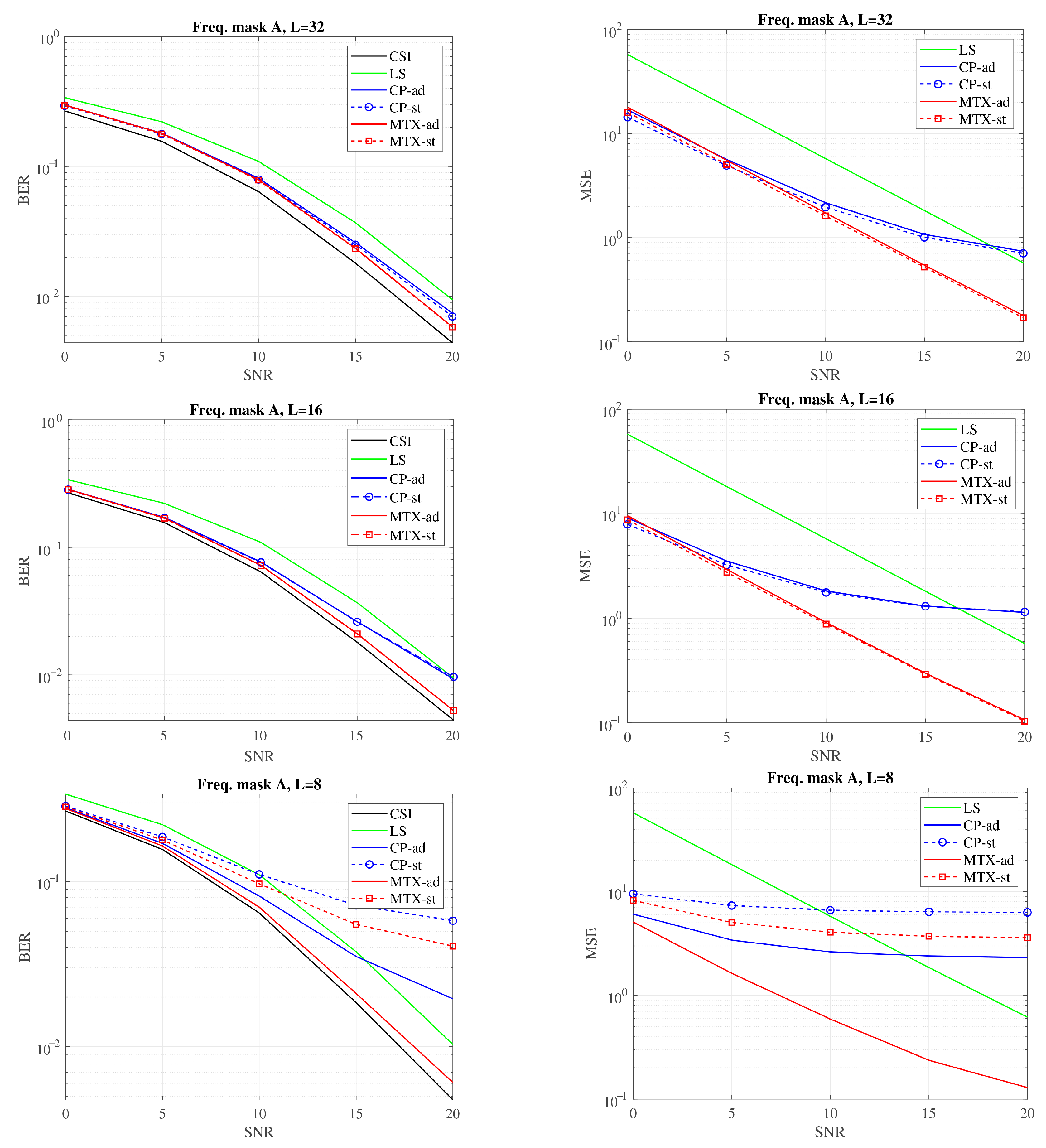
Figure 6,
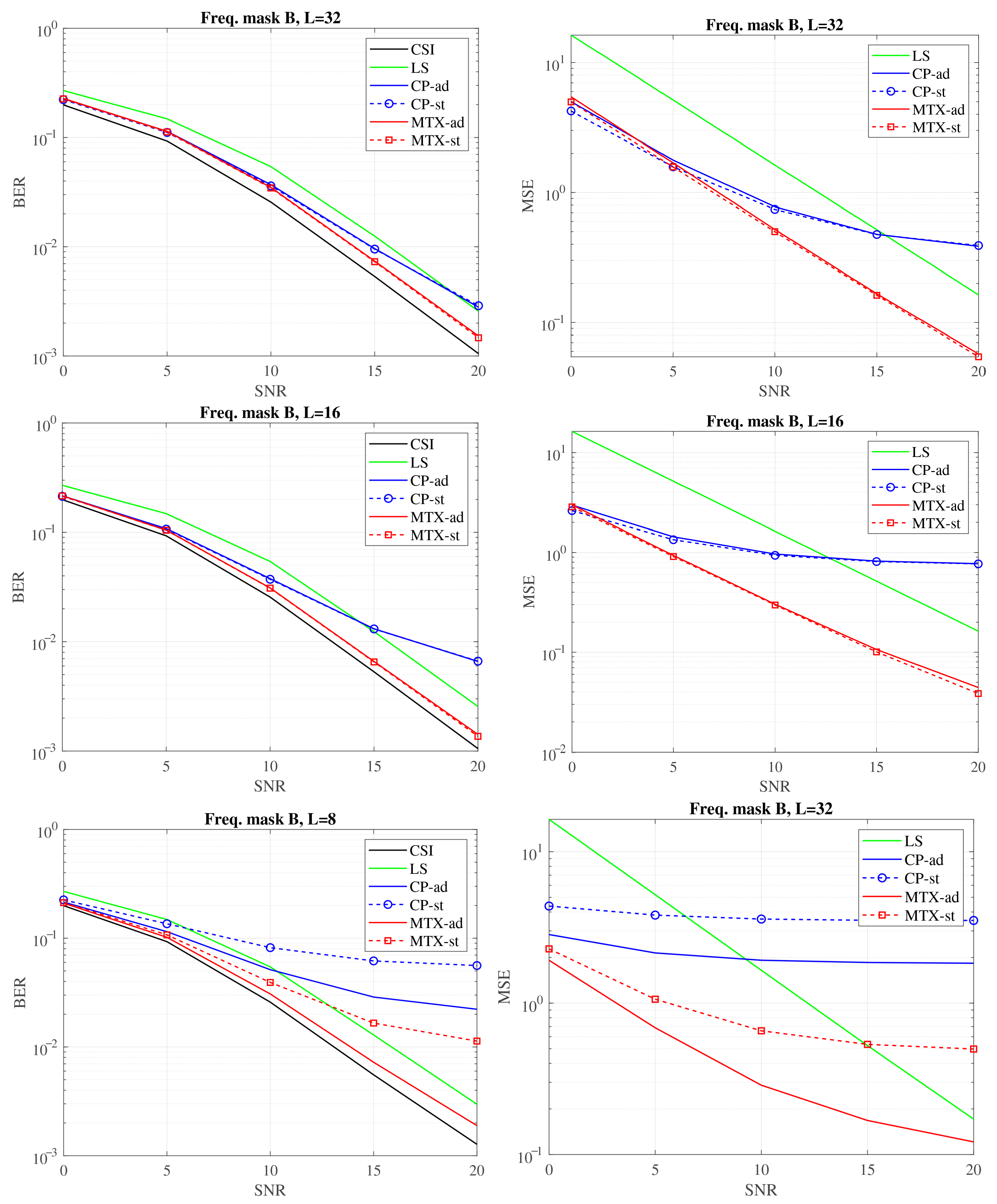
Figure 7 and
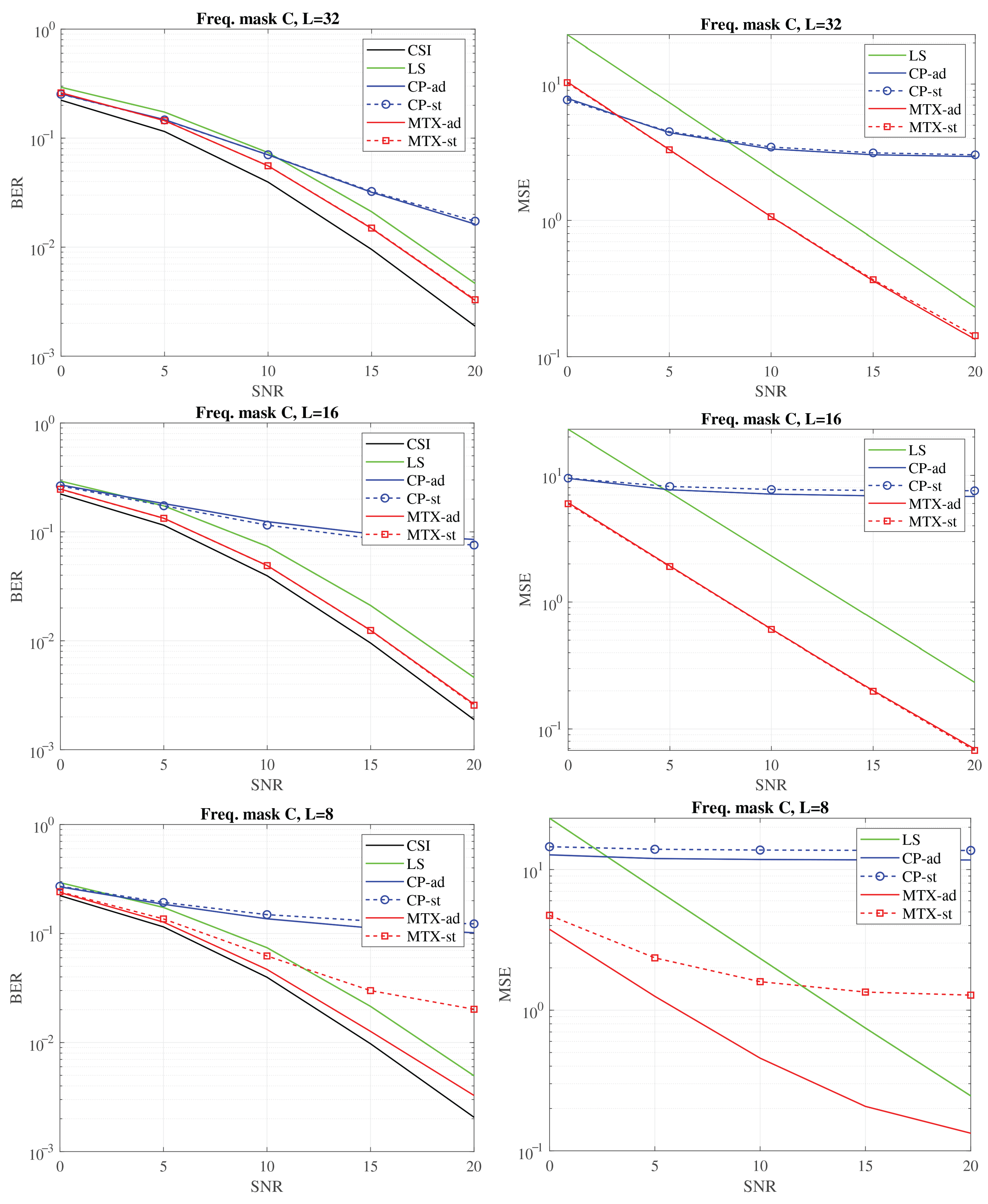
Figure 8 illustrate the BER and MSE performance metrics for signal transmission over the same group of channels using different frequency masks. The aim was to investigate scenarios where the system, encountering varying relationships between the guard interval (GI) length and the channel delay spread, retrieves channel characteristic using only the symbols on the active subchannels. The results demonstrate that the approach utilizing the precomputed matrix is highly effective, yielding the best performance.
No significant difference is observed between the “-st” and “-ad” versions when the channel delay spread M is significantly smaller than the guard interval length L. This condition is exemplified in experiments conducted with L values of 32 and 16 samples. In such cases, the impulse response length remains less than half of the GI length, even when accounting for the dispersion in the channel impulse response caused by the analog filters’ bandwidth limitations. Thus, regardless of synchronization fluctuation effects, a time mask length equivalent to L is sufficient to encompass the entire impulse response in each instance.
A different situation occurs when , which was comparable to the channel delay spread. Uncompensated fluctuations in the determination of symbol timing may cause the fixed time mask to miss significant portions of the impulse response. As a results, channel estimation errors are much more severe and become particularly evident at high SNR levels. The proposed solution, incorporating CIR energy evaluation, proved to be an effective remedy, maintaining system quality regardless of the frequency mask shape used in the simulations. Some improvement was also observed with the “CP-ad” method; however, the effect of the frequency mask often caused performance to fall below that of the simplest LS algorithm.
The larger bit error rate (BER) values observed in the experiment when using the mask A are associated with transmission over a greater number of subchannels, including those with significant attenuation, leading to substantial distortion of the received symbols. The number of active subchannels assigned to the corresponding mask is shown in
Table 4.
The classic “LS” algorithm exhibits the lowest computational complexity. The “CP” method introduces two additional FFT transforms, which are further supplemented by multiplication with a CMT matrix in the “MTX” method or replaced by a CMF matrix, depending on which approach offers greater computational efficiency (as analyzed in the previous section). Additional numerical overhead is introduced by the channel impulse response offset compensation mechanism used in the “-ad” scenarios. However, this complexity is significantly lower compared to the determination of a new matrix, which would require a matrix inversion operation.
To quantitatively assess the increased computational complexity introduced by the modified methods relative to the baseline Least Squares (LS) algorithm, an overhead metric is defined as the ratio of the additional number of multiplications to those required by the LS method. For the “
CP” method, the metric is given by:
whereas for the “
MTX” approach, it is expressed as:
Table 5 presents the computed values of the overhead metric for the considered simulation scenarios.
As shown in
Table 5, the “
CP” method leads to a substantial increase in the number of multiplication operations. However, this added complexity must be weighed against its potential to reduce estimation errors caused by spectral and temporal leakage—an issue particularly prominent when the values of
L and
M are comparable. The “
MTX” method, which refines the channel estimation by leveraging the matrix
in a direct formulation, also introduces a marked increase in computational cost, as reflected in the final row of
Table 5. Nevertheless, when favorable conditions are met, this complexity can be significantly reduced by employing the proposed three-stage decomposition of the matrix computation.
5. Relation to Compressive Sensing and Deep Learning-Based Channel Estimators
Compressive Sensing (CS) and Deep Learning (DL) represent modern techniques for enhancing channel estimation, often with the potential to surpass conventional pilot-assisted linear methods. In CS, the dominant delay taps of CIR are first identified through sparse support detection, after which their amplitudes are refined via Least-Squares (LS) projection [
38]. DL, in contrast, reverses this sequence: a neural network directly produces an enhanced channel response, with a preliminary LS estimate typically serving as an input feature map rather than a post-processing stage [
12,
39].
Table 6 provides a qualitative side-by-side comparison between the analyzed
approach, greedy CS algorithms and representative DL estimators reported in the literature.
The method investigated in this work can, in principle, be combined with greedy CS algorithms such as OMP by applying the MTX matrix concept after path delay identification. However, in such a scenario, the matrix would need to be computed online or multiple precomputed instances for various delay supports would have to be stored in memory. In practice, the performance of CS estimation depends critically on accurate delay detection, which becomes challenging when pilots occupy only a limited number of subbands. The resulting spectral gaps cause time-domain energy leakage into adjacent impulse response coefficients. To simplify implementation, we therefore assumed here that the cyclic prefix spans the entire delay spread, ensuring that the matrix remains constant and eliminating the need to track the support set for each frame. Developing efficient strategies to update this matrix remains an open problem for future investigation.
Compared to greedy CS methods, DL-based channel estimators are appealing because they can learn the complex time-frequency structures of wireless channels, which are difficult to model analytically. They function as powerful denoisers and interpolators and can maintain high accuracy under low pilot density or substantial transmission impairments, provided that these conditions are reflected in the training data. In model-based variants, the neural network refines LS/DFT estimates by reducing residual errors, whereas in data-driven variants, it replaces the conventional channel estimation block entirely.
Given the scenario considered in this manuscript (slow-varying channels with block-type pilots across all subcarriers), a purely analytic solution remains the pragmatic option. Qualitatively, the literature indicates that with a full pilot symbol, linear estimators already exploit nearly all available information, leaving limited room for DL to improve the decision quality. Moreover, the MTX approach is preferable under the assumed conditions because it:
Requires only pilot signals as training data and no model maintenance, avoiding domain-shift issues and retraining overheads intrinsic to DL;
Offers deterministic, low and fixed online complexity and latency (FFT + small matrix–vector products), and can be mapped directly to FPGA/DSP blocks;
Is robust to SNR/channel mismatch by design (there are no learned weights whose validity depends on a training envelope);
Is hardware-transparent and easily verifiable/certifiable (no black-box parameters), which eases integration;
Exploits the design choice in the paper that the entire cyclic prefix spans the delay spread. This yields a time-invariant matrix and removes the need for adaptive CIR support tracking.
Importantly, a hybrid scheme combining MTX and DL could be a promising next step in the extended estimation procedure. In this scheme, the deterministic MTX-based front end would remain intact while a small neural module would learn a residual correction of the channel using a nonlinear denoiser or interpolator, for example, or softly modulate the MTX mask by predicting an effective delay span. This design could leverage the strengths of DL, particularly its ability to exploit learned time-frequency structures at low pilot densities or under moderate impairments, while preserving the hardware transparency and fixed latency of the analytic backbone.
Nevertheless that integration is non-trivial and beyond this paper’s scope because it would require a representative training/validation corpus for the slow-varying, block-pilot regime. Furthermore, the room for DL improvement over linear processing is limited with a full pilot symbol. For these reasons, we propose investigating MTX + DL as a means of improving BER at lower pilot budgets or under mild model mismatch in future work.
6. Conclusions
The paper has presented a detailed discussion of a channel estimation method that employs a precomputed CMF (or CMT, depending on computational complexity) enhancement matrix. These matrices are derived from vectors representing the active region of the CIR (time mask) and the active subcarriers of the CFR (frequency mask), thereby enabling a more accurate and reliable reconstruction process. This effectiveness has been validated through simulation analyses against reference methods that also rely solely on active subcarriers for channel reconstruction.
In the simulation study, symbol synchronization fluctuations, which affect the position of the time mask and, consequently, the structure of the precomputed matrix, were addressed. To eliminate the need for storing or computing multiple matrix variants in real-time, a compensation method based on the energy distribution of impulse response coefficients was proposed.
Additionally, with focus on minimizing the number of multiplication operations, a condition was derived to determine the minimum number of subcarriers above which, for a given value of M, the FFT-based approach using the CMT matrix becomes more computationally efficient than direct multiplication using the CMF matrix. An analysis of computational efficiency across different values of active subcarriers A and channel delay spread M was performed.
Future work will concentrate on practical implementation aspects, including hardware deployment on FPGAs or DSPs to evaluate real-time performance and resource efficiency. Validation in real-world channel conditions will be conducted to assess robustness in the presence of multipath propagation and Doppler effects. Further research will explore adaptive time/frequency masking strategies and the integration of the proposed method into complete receiver architectures to enhance flexibility and system compatibility. Additionally, efforts will be directed toward developing efficient matrix update techniques aimed at minimizing computational overhead. The aforementioned integration with DL is also being considered.

