Abstract
The increasing interest shared by academia and industry in the development of RISC-V cores, extensions and accelerators becomes fructified by collaborative efforts, like the EU’s ChipsJU, which leverages the design of building blocks, IPs and cores based on RISC-V architecture. A domain capable of benefiting from the RISC-V extensibility is the control of external DACs and ADCs. The proposed solution is an open-source RISC-V extension for optimized control of external DACs and ADCs called RiscADA. The extension supports a parametrizable number of DACs and ADCs, is integrated as a coprocessor beside CVA6 in a SoC by using the CV-X-IF interface, deployed on a Kintex UltraScale+ FPGA and implements ISA extension instructions. After benchmarks with commercial solutions, the results show that CVA6 using RiscADA extension configures external DACs 38.6× and 10.9× times faster than MicroBlaze V and simple CVA6, both using AXI SPI peripherals. The proposed extension achieves 5.35× and 3.05× times higher sample rates of external ADCs than the two configurations mentioned above. RiscADA extension performs digital signal conditioning 4.52× and 3.1× times faster than the MicroBlaze V and CVA6, both using AXI SPI peripherals. It computes statistics for external ADC readings (minimum, maximum, simple-moving average and over-threshold duration).
1. Introduction
The classical VLSI laws, which historically dictated the evolution pace of the processors in terms of frequency, power consumption and integration scale, are nowadays slowed down (e.g., Moore’s) or obsolete (e.g., Dennard’s). The digital designers involved in proposing and developing the architectures needed for meeting the modern requirements of embedded computing, high performance computing, machine learning and advanced automation techniques are facing the limitations of the current silicon-based technologies.
The last few years of computer engineering have shown unprecedented collaboration efforts between universities and companies for designing RISC-V cores, peripherals, extensions, hardware accelerators, drivers and software libraries. Silicon industry companies, which built their wealth and reputation on the proprietary hardware paradigm, never disclosing all the internal details of their processors (or no detail at all) and were always competing to design better performing computing machines, are working together with universities in projects meant to leverage the industrial adoption of the open-hardware RISC-V architecture [], into domains such as high-performance computing, automotive, space, IoT, etc. Many European projects as the ones grouped in the Chips JU [] or European Processor Initiative/EuroHPC JU [] are meant to make RISC-V the de facto standard in Europe for designing and manufacturing families of low-power processors, building blocks, IPs, platforms, compilers and software libraries for general-purpose microcontrollers and also for high-performance computing, big-data and emerging applications. An extended analysis performed by the SHD Group revealed that the RISC-V market reached “$6.1B in 2023, a growth of 276.8% over 2022 and is forecast to grow to $92.7 B by 2030…” ([]).
Due to the open-hardware nature and due to the educational and industrial interest shown in this subject, the RISC-V architecture easily became the most popular platform for designing and deploying hardware accelerators and extensions. These hardware accelerators are implementing software-oriented algorithms in a hardware manner for bringing the control of various hardware structures closer to the instruction level for achieving better time performance and lower energy consumption.
One engineering field that can benefit from the integration into a RISC-V extension is the control of external DACs (digital-to-analog converters) and ADCs (analog-to-digital converters). The author of the book [] states that because we live in an analog world, where “most of the stimuli we experience in daily life—sounds, sights, tactile stimuli—are continuous in time”, “most important applications of digital signal processing involve processing analog signals”. External DACs and ADCs are present in many applications like data acquisition systems and laboratory instrumentation, control systems, signal processing, telecommunications, medical devices, audio and video equipment. After searching for publications targeting both RISC extensibility and external A/D and D/A converters control and not being able to identify such work, the authors are proposing a RISC-V extension for this purpose.
This article presents the design of an open-source RISC-V extension featuring improved time performance and resource utilization for controlling external 12-bit DACs and ADCs with an SPI-like interface, named RiscADA. Integrated as a coprocessor through CV-X-IF interface with CVA6 RISC-V core in the Ariane SoC proposed by OpenHW Group [] and deployed on a Kintex UltraScale+ FPGA, RiscADA extension is able to configure an external DAC 38.6× times faster than an AMD MicroBlaze V and 10.9× times faster than a CVA6 core, both using Xilinx AXI Quad-SPI peripherals.
The proposed solution achieves 5.35× and 3.05× times higher sample rates of reading external ADC measurements than the two configurations enumerated above. By performing digital signal conditioning, RiscADA extension detects an over-threshold signal 4.52× and 3.1× times faster than MicroBlaze V and the CVA6 core controlling the converters with Xilinx AXI Quad-SPI peripherals. The RiscADA extension is scalable, being able to control up to 64 external DACs and up to 64 external ADCs.
The RiscADA extension is addressing the applications where the required number of external ADCs and DACs exceeds the number of SPI peripherals offered by microcontrollers (MCUs) or the number of digital outputs that can be used as chip-select for converters placed on the same SPI bus. These applications may include but are not limited to systems for industrial process control, medical systems, automated test systems for automotive ECUs, logic analyzers, etc.
The main contributions of this paper are: the open-source RISC-V extension for optimized control of parametrizable numbers of external DACs and ADCs distributed together with a CV-X-IF ([]) adapter designed for integration as a coprocessor beside ([]), a GNU/GCC-compatible C library for using the extension without modifying the compiler and the experiments proving the performance improvements gained by using dedicated hardware accelerators instead of classical memory-mapped peripherals. The RiscADA extension HDL files and the dedicated C library files are available in the kcu116 branch of the CVA6 repository fork at https://github.com/cosminandreipopovici/cva6/tree/kcu116 (accessed on 1 July 2025).
The second section provides information on the related work and the third shows the analysis of the available commercial solutions. The fourth section illustrates the architecture of the proposed solution and the fifth brings up the discussion on the tests, experiments and benchmarks used for the solution validation.
2. Background
Due to the fact that current research focuses on on-chip converters connected to RISC-V architectures [] and because the control of external converters is used in niche applications, this section will briefly describe some publications that involve RISC-V cores controlling on-chip ADCs and DACs.
Article [] presents the design of a microcontroller based on a 32-bit RISC-V core and integrating a 10-bit SAR ADC and a 12-bit DAC connected to the core through an APB bridge placed on an AXI4-Lite bus. The SAR ADC offers a 10 MHz maximum sample rate and supports a differential input. The DAC is capable of 100 ns setting time. The microcontroller is implemented in 130 nm CMOS technology.
The authors of paper [] are introducing a SoC integrating a PicoRV32 core and an 8-bit SD ADC (Sigma-Delta ADC). An interconnect element processes the end-of-conversion events from the ADC and feeds the acquired data to the RISC-V core when requested. The SoC validation was performed using UVM and the implementation technology chosen was TSMC 65 nm.
The design and the parametrized generation of signal analysis SoC is addressed in papers [,]. The architecture presented in these papers shows two main components: a general-purpose RISC-V core (Rocket CPU implementation) with a vector processing extension and a DSP Accelerator featuring a TISAR ADC and a signal filtering chain with multiple components. The RISC-V core, which is placed on a TileLink Crossbar and the DSP Accelerator, which is placed on an AXI4 bus, communicate through a Memory-Mapped IO Manager. The SoC offers an efficiency of 19 TOPS/W and 23 GFLOPS/W, is implemented in 16-nm CMOS technology and can be used in applications like spectrometry, radar signal processing, etc.
The paper [] introduces a Linux-capable RISC-V core called DVINO (Drac Vector IN-Order) with a two-lane vector processing unit. The SoC containing DVINO integrates an ADC with a 9-level second-order Delta-Sigma modulator.
The authors of the report [] describe a RISC-V-based SoC used as an encryption accelerator featuring integrated ADCs and DACs. The designed DAC is differential and has a sampling rate of 9 MS/s, and the designed DAC is a differential 8-bit SAR ADC having a 1 MS/s sample rate. The most valuable thing about this report is the fact the project is a combination of digital design and analog design efforts of the students proposing the SoC.
The paper [] addresses the challenges of designing terahertz (THz) transceivers. The terahertz communication is implemented using the Modified PWM technique for controlling a PWM-DAC. The PWM-DAC is integrated into a 32-bit RISC-V core implemented in 180 nm CMOS and tested on an Artix-7 FPGA (XC7A200TFBG484-3).
For offering an example of an industrial grade product, the authors analyzed the application note [], which describes the scan mode operation of the 12-bit SAR ADC embedded into the Renesas R9A02G021 ([]), an MCU equipped with a low-power 48 MHz 32-bit RISC-V core, 128 KB of code flash memory and 16 KB of SRAM memory. The MCU also features a dual channel 8-bit DAC.
Other examples of already produced RISC-V-based microcontrollers are the GD32VF103 ([]) family produced by GigaDevice. These 32-bit RISC-V MCUs feature two 12-bit SAR ADCs with a sample rate of 1 MS/s and configurable resolution (6-bit, 8-bit, 10-bit or 12-bit) and two 12-bit DACs with selectable resolution (8-bit or 12-bit). The DACs can be triggered by a dedicated timer interrupt or by an external interrupt using DMA support for loading values to be converted.
The papers briefly described above present internal DACs and ADCs placed on the same SoC with RISC-V cores. Even though the on-chip connection to the core offers high-speed access to these peripherals, the small number of A/D and D/A channels (1–2) are not enough for applications requiring controlling/monitoring high numbers of analog signals from domains like active safety in automotive, aerospace, medical and energy industries. In comparison with the converters of this SoCs, the proposed extension is scalable and can be parametrized to control up to 64 external DACs and up to 64 external ADCs. This is the main advantage of using RiscADA extension for external converters instead of RISC-V-based SoCs with internal converters.
Because the authors of this paper used the CV-X-IF specialized coprocessor connection interface proposed by OpenHW Group for connecting RiscADA to the CVA6 RISC-V core, two publications related to CV-X-IF are mentioned below.
The authors of the paper [] are using the CV-X-IF to connect to the CV32E40X core ([]), a hybrid accelerator for Post-Quantum Cryptography CRYSTALS algorithms. The accelerator offers 7.74× and 4.12× performance improvements for Kyber’s and Dilithium’s algorithms in comparison with the baseline software implementation.
The article [] proposes automated methods for integrating new custom instructions of co-processors into the compiler toolchain, the first method being used for building an “automatically retargeting compiler toolchain” and the second one for generating CV-X-IF compatible co-processors.
3. Available Commercial Solutions
The available market solutions for integrating a high number of external DACs and ADCs may fall into one of the following categories:
- Microcontrollers and DSPs with a high number of SPI peripherals;
- Custom HDL designs for FPGAs with high logic resources and pin count for controlling as many external DACs and ADCs as needed;
- Customizing CPU soft-core IPs such as Xilinx MicroBlaze, AMD MicroBlaze V (RISC-V soft core), Intel Nios II or Nios V, LatticeMico32, etc., to accommodate as many SPI peripherals as needed for the application requirements for external DACs and ADCs.
The highest number of SPI peripherals on a microcontroller is around 5–6 units, some examples being the STM32F427 and STM32F429, Arm Cortex-M4 cores with floating point units and digital signal processing units running at 180 MHz.
Custom HDL designs for FPGA may benefit from high numbers of digital pins offered by some series of FPGAs, such as Xilinx Kintex-7. The engineer developing the HDL design can choose to instantiate as many control blocks for the external converters as the application requires within the limits of the available logic resources and pin count. If the acquired data needs to be recorded on a hosting PC, a high-speed communication interface must be used. National Instruments offers FPGA cards with PCIe communication, such as NI PCIe-7820R that features a Kintex-7 160T with 128 digital pins. Considering external DACs and ADCs need only 3 of the 4 SPI pins (CS, CLK and MOSI for DAC and CS, CLK and MISO for ADC), this FPGA board can accommodate 42 external DACs or ADCs.
The alternative to making custom FPGA designs is using validated IPs like soft-cores and SPI peripherals. The option analyzed by the authors of this work is using an AMD MicroBlaze V soft-core IP together with Xilinx AXI Quad-SPI peripherals on a Xilinx Artix-7 XC7A100TCSG-1 FPGA. After a resource utilization analysis and after generating a valid bitstream file, the authors concluded that this solution can accommodate up to 30 external ADCs or DACs.
The performance comparison between using the Xilinx AXI Quad-SPI and the proposed solution is illustrated in the fifth section of this article.
4. Architecture of the Proposed Solution
The proposed solution for controlling external 12-bit DACs and ADCs called RiscADA (Figure 1) is a RISC-V extension implementing R-format instructions []. The extension has the following interfaces:
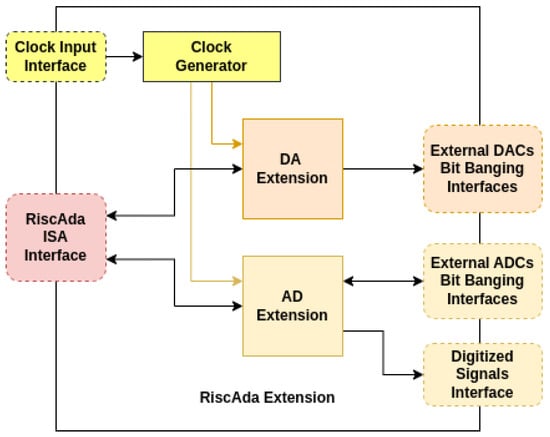
Figure 1.
Block Diagram of the RiscADA Extension.
- Clock Input Interface: used for receiving the main CPU clock;
- ISA Interface: used for receiving the instructions fields and source registers values for setting/getting values, for performing configurations, and for sending data back to the main CPU;
- External DACs Bit Banging Interfaces: parametrized number of interfaces for controlling external DACs, each of them exposing CS, CLK and MOSI signals;
- External ADC Bit Banging Interfaces: parametrized number of interfaces for reading measurements of external ADCs, each of them exposing CS, CLK and MISO signals;
- Digitized Signal Interface: output signals resulted from the digital signal conditioning of the inputs read by the external ADCs.
The RiscADA Extension has a simple structure, being composed of three main modules:
- Clock Generator: module used for generating the two clock signals for the DA Extension and for the AD Extension, necessary because external DACs and ADCs have different minimum and maximum operating frequencies; these two clock signals are generated using a clock dividing technique;
- DA Extension is the sub-extension of the RiscADA Extension responsible for the control of the external DACs and including a parametrized number of DA Blocks;
- AD Extension is the sub-extension of RiscADA Extension used for reading the external ADCs and for computing basic statistics on the sampled signals and includes a parametrized number of AD Blocks; it is also responsible for the digital signal conditioning of the analog inputs; in this context, digital signal conditioning refers to reading an analog input, comparing its value to a preconfigured threshold and setting an digital output to logic ‘1’ if the value exceeds the threshold (plus a hysteresis value) or to logic ‘0’ if the value drops under the threshold (minus the hysteresis value).
4.1. Architecture of the DA Extension
The DA Extension, used for controlling the external 12-bit DACs, offers the following functionalities:
- Setting an instant analog value on one DAC channel or the same value on all channels simultaneously;
- Configuring and starting a sequence of maximum 10 analog levels, each of them having a duration of maximum 4096 µs; preconfigured sequences for multiple channels can be started simultaneously.
The DA Extension, illustrated in Figure 2, is composed of the DA Sequencer and the DA Block module. The DA Sequencer receives the instruction fields and the source registers’ values from the ISA interface, sends them to the DA Blocks and sends back the responses from these blocks to the ISA interface for the destination register to be written back. The DA Block is a parametrized module that instantiates at synthesis the declared number of blocks equal to the number of external DACs to be controlled.
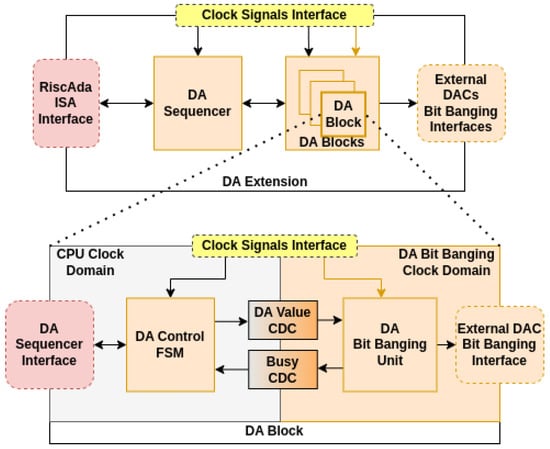
Figure 2.
Architecture of the DA Extension (top) and Architecture of a DA Blocks (bottom).
The DA Block is split into two clock domains. The first clock domain, where the source clock is the RISC-V core clock, contains the DA FSM Control, which implements the instant analog value setting and also the configuration of the multiple analog levels sequence. The source clock for the second domain is the clock divided for the DA Extension. This domain uses the divided clock for DA Extension as the serial clock for controlling an external DAC and contains the DA Bit Banging Unit. This unit outputs the instant values or the values from an analog sequence to the DAC by using the SPI-like protocol.
There are two data exchange processes between the two clock domains. The first exchange is the 12-bit digital-to-analog value passed to the DA Bit Banging Unit and the second one is the busy flag of the same unit that has to be read by the DA Control FSM and sent back to the ISA interface when requested by the dedicated instruction. This data exchange between the clock domains is performed by two CDCs implemented in a double register manner. These modules are implemented by the authors and are not related to the AMD CDC IP with the same name.
Setting the same instant value on all DA channels or configuring and starting a 10-value analog sequence on multiple channels can be performed simultaneously because all DA Blocks are using the same clock (the divided clock for DA Extension).
4.2. Architecture of the AD Extension
The AD Extension, illustrated in Figure 3, used for reading analog measurements from 12-bit external ADCs offers the following functionalities:
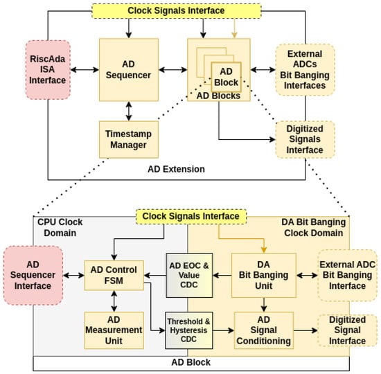
Figure 3.
Architecture of the AD Extension (top) and Architecture of an AD Block (bottom).
- Reading the latest instant analog measurement;
- Setting and getting the values of threshold and hysteresis for the digital signal conditioning process;
- Performing the digital signal conditioning;
- Computing basic statistics over the sampled signals in order for them to be accessible by the CPU without additional computational effort: simple moving average over 16 samples, minimum, maximum and the latest over-threshold duration of the signal.
The AD Extension is formed by the AD Sequencer, the AD Blocks and Timestamp Manager. The AD Sequencer is the gateway between the ISA interface and the AD Blocks. The Timestamp Manager, a 32-bit timer, provides the timestamps for the values measured by external ADCs and for statistics. The AD Blocks module is parametrized with the necessary number of external ADCs.
The AD Block is composed of two clock domains. The RISC-V core clock domain contains the AD Control FSM, which obtains the analog values read as digital samples and feeds them to the AD Sequencer and to the AD Measurement Unit. AD Control FSM also transmits threshold and hysteresis settings to the Signal Conditioning module. The second component in the RISC-V clock domain is the AD Measurement Unit, which always computes minimum, maximum, simple-moving average over 16 samples and over-threshold duration.
The source clock for the second domain is the clock divided for the AD Extension. This domain uses the divided clock for AD Extension as the serial clock of the external ADCs and contains the AD Bit Banging Unit and the AD Signal Conditioning module. The AD Bit Banging unit reads in a loop measurements from the external ADC. The two clock domains are exchanging data through the CDCs implemented by the authors as the ones described in the previous sub-section.
All AD Blocks sample their corresponding channels, computing the statistics mentioned above, and performing the digital signal conditioning simultaneously and these processes are also synchronized due to using the same clock signal (the divided clock for AD Extension). These processes are unattended, the ADC converters being polled as fast as possible and the latest acquired measurements being used for computing statistics and digital signal conditioning. The statistics kept by each AD Block can be reset one at a time or all simultaneously.
4.3. Integration of RiscADA in Ariane SoC
4.3.1. RiscADA Extension Integrated as Coprocessor for CVA6
The RiscADA extension was integrated as a coprocessor into the Ariane SoC (Figure 4) beside CVA6 [] (CV64A6-IMAFD—RV64IMAFD) using the CV-X-IF interface [], a specialized interface for connecting co-processors to the main core. For the purpose of integration, the authors designed a CV-X-IF adapter, which implements an FSM for performing the handshaking between the RiscADA extension and the signals of the coprocessor interface. The RiscADA extension files added by the authors to the CVA6 repository fork available at https://github.com/cosminandreipopovici/cva6/tree/kcu116 (accessed on 1 July 2025) are organized in the directories at the following paths:
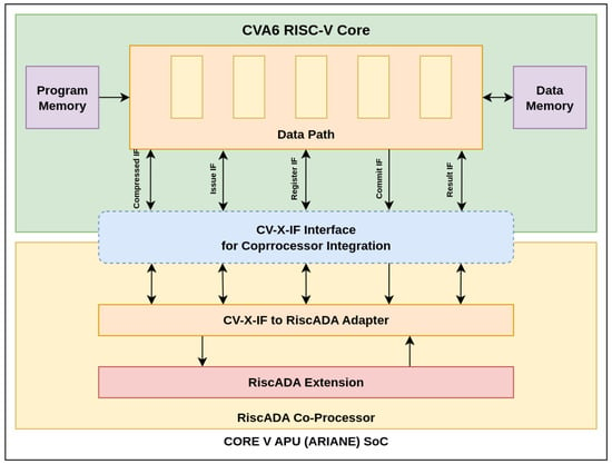
Figure 4.
RiscADA Extension connected to CVA6 using CV-X-IF inside Ariane SoC.
- /core/riscada—RTL files describing the RiscADA extension, the CV-X-IF adapter and the coprocessor wrapper;
- corev_apu/fpga/constraints—the constraints file for the AMD KCU116 FPGA development board ([]);
- /verif/tests/custom/riscada—the files of RiscADA C library based on inline assembly snippets for GCC compiler ([]) named ADA_functions.h and ADA_functions.c and the C tests file riscada_tests.c; also, the Gtkwave template file is available in this directory;
- /verif/regress/—the bash script for starting the execution of the RiscADA tests named riscada_c_tests.sh.
The concept of using CV-X-IF is simple: every instruction not recognized by the main core as legal from the opcode point of view is passed to the coprocessor together with the source registers’ values; the coprocessor chooses to accept and execute it or not and to feed back the results for writing data to the destination register. The RiscADA extension together with the adapter are instantiated into the RiscADA coprocessor and connected with CV-X-IF to the CVA6 core.
4.3.2. Clock Generation Considerations for RiscADA Extension Integration
An important mention from the integration point of view is related to the clock resources for the RiscADA. The Clock Generator module illustrated in Figure 1 divides the main RISC-V clock frequency into two different clock frequencies needed by DA and AD extensions. The two generated clock signals are used in the DA and AD Block as clock sources for the bit-banging units and as serial clock signals for the controlled converters.
The clock dividing mechanism, preferred by the authors for offering a vendor-independent design in terms of FPGA implementation, can be replaced by the designers who want to integrate RiscADA into their RISC-V-based SoCs with clock enabling techniques, with clock generation IPs or with clock buffer primitives specific to their FPGA target.
4.3.3. DMA Support as Integration Future Work
The OpenHW Group, the current maintainers of CVA6 project are offering two classes of RISC-V cores. The first one is the Linux-capable processors like CVA6, part of the Ariane SoC, which can be synthetized for AMD FPGAs. The CVA6-based SoC named Ariane does not feature any DMA cores. The second class is the microcontroller class featuring cores like CV32E40P ([]) for CORE-V-MCU SoC ([]). The CORE-V-MCU features the uDMA core ([]), a DMA subsystem designed for easy memory transfers with peripherals implementing communication interfaces like I2C, UART, SPI, or GPIO interfaces.
Even though CORE-V-MCU has DMA support and CVA6 does not, the authors have chosen CVA6 core for its CV-X-IF specialized coprocessor interface for RiscADA integration. For transferring all concurrently acquired ADC measurements from RiscADA to RAM memory or for transferring parameters for analog values or sequences to be configured and started in parallel on DAC converters, a DMA subsystem must be integrated as a future improvement. The approach proposed for further analysis and implementation implies modifying the CVA6-based Ariane SoC for integrating the uDMA core provided by the OpenHW Group:
- Making an AXI-to-APB or AXI to an AXI-to-AXI-lite bridge due to CVA6 usually using AXI4 and UDMA using APB or AXI-lite;
- Mapping uDMA registers into CVA6’s address space;
- Connecting the bridge mentioned above for uDMA to AXI interconnect of CVA6;
- Connecting uDMA’s interrupts outputs to the PLIC used by CVA6 and updating the CVA6 interrupts vectors;
- Modifying the Linux device tree for defining the channels to be used by uDMA.
4.4. Architecture of ISA Extension
The ISA extension designed for operating the RiscADA accelerator contains R-format instructions for controlling both sub-modules, DA Extension and AD Extension.
The instructions listed in Table 1 has the opcode 7’b1111011 and were designed for controlling the external DACs:

Table 1.
RiscADA Extension Instructions.
- da_set_val —this instruction is used for setting an instant analog value (12 bits) on an external DA channel selected by address; by setting the most significant bit in funct3 field, the value can be set on all channels (channels broadcast); the val_12 in the rs2 operator is the 12-bit analog value to be configured on an external DAC channel;
- da_set_seq_len—instruction used for setting the number of levels in an analog sequence for an DA channel selected by address; it supports channels broadcast; the len_4b in the rs2 operator is the 4-bit length of the analog sequence to be configured and has a maximum value of 10;
- da_set_seq_vals—this instruction sets the values of each level in an output analog sequence (maximum 10 values, 12 bits each); it supports channels broadcast; the vals04_60b and vals59_60b are the first and second groups of 5 12-bit analog values of the sequence to be configured;
- da_set_seq_durs—this instruction sets the duration of each level in an analog sequence (maximum 10 values, 12 bits each, resolution in microseconds); it supports channels broadcast; the durs04_60b and durs59_60b are the first and second groups of 5 12-bit analog durations of the values of the sequence to be configured;
- da_set_seq_start—this instruction starts an analog sequence for an external AD channel selected by address;
- da_get_val—this instruction is used for retrieving the latest configured instant analog value set on an external DA channel;
- da_get_seq_running—this instruction retrieves the mask holding logical ‘1’s on the positions indicating DA channels which are running an analog sequence;
- da_get_busy—this instruction retrieves the mask having logical ‘1’s on the positions indicating which DA channel bit banging unit is busy configuring an external DA to avoid overwriting the DA value.
The instructions designed for the interaction with the external ADCs and for getting the computed statistics of the sampled signals are:
- ad_reset_stats—issuing this instruction will reset all statistics (minimum value, maximum value, simple moving average, latest over-threshold duration); when issued on broadcast, it will also reset the timestamp timer;
- ad_set_thr_hyst—this instruction is issued for setting the threshold and the hysteresis values for the signal conditioning/over-threshold detection; thr_12 and hyst_12 are the 12-bit values of threshold and hysteresis for the digital signal conditioning;
- ad_get_stats—this instruction is used for retrieving all the statistics measured from an AD channel and the latest instant value read;
- ad_get_thr_hyst—this instruction retrieves the latest threshold and hysteresis values set on an AD channel;
- ad_get_val—instruction used for getting the instant value of an external AD channel together with its 32-bit timestamp (microseconds); ad_val is a 12-bit instant value read from an external ADC channel;
- ad_get_otd—instruction used for getting the latest over-threshold duration for an AD channel and the timestamp; otd is the 12-bit over-threshold duration recorded for a sampled analog input;
- ad_get_sma16—instruction used for retrieving the simple-moving average value (performed on 16 samples) and the timestamp of its retrieval; sma is the 12-bit instant simple moving average performed on the last 16 samples for a sampled analog input;
- ad_get_max—instruction used for retrieving the maximum measured value for an AD channel and the timestamp of its retrieval; max is the 12-bit maximum value recorded for a sampled analog input before the last statistics reset operation was performed;
- ad_get_min—instruction used for retrieving the minimum measured value for an AD channel and the timestamp of its retrieval; max is the 12-bit minimum value recorded for a sampled analog input before the last statistics reset operation was performed.
4.5. C Library for the RiscADA Extension
For using the ISA extension instructions designed for RiscADA in order to test the solution, two options were identified:
- Writing ASM “.word” macros with parametrized source and destination registers for the new instructions in order to be inserted by the assembler/linker when writing the binary file;
- Using extended inline assembler snippets in C code for writing the functions that will compose the C library for RiscADA extension.
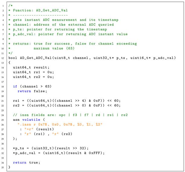
The second option was chosen due to the fact that the GNU Toolchain for RISC-V supports extended inline assembler code and because this option enabled the use of the RiscADA extension from C code without modifying the compiler. An example of a function implemented in this manner is presented in Listing 1.
| Listing 1. Example of RiscADA library function implementation based on inline assembler code. |
 |
5. Evaluation, Results, Discussion
5.1. Design Validation by Simulation
For validating the RiscADA extension, every instruction was tested by writing tests in C and running them in the simulator using Verilator [] version 5.008. Validating the functionalities of the instructions involved comparing set and get configured values, analyzing the generated waveforms and creating a mock-up for the output data signal of the AD converter in order to simulate a sampled analog input signal. All the instructions were also tested in a black-box testing manner without using a RISC-V core in Vivado Xsim simulator ([]) and in Verilator.
The simulation waveform snippet presented in Figure 5 illustrates the execution of the da_set_val and da_get_val on the RiscADA extension integrated as a coprocessor into CVA6 in the context of instructions testing. After an analog value is set with the dedicated instruction, its value is retrieved with the counterpart getter instruction. If the values are equal, the test continues with the next analog value to be set.
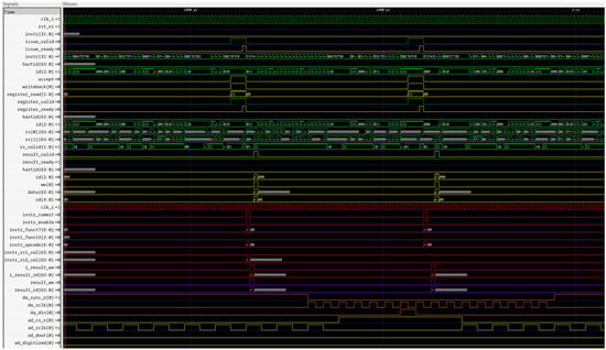
Figure 5.
Simulation illustrating execution of da_set_val and da_get_val instructions.
5.2. Testing the Solution on FPGA
For testing the RiscADA solution in a real environment, the Ariane SoC with Xilinx peripherals (containing the CVA6 core and the RiscADA extension interconnected through CV-X-IF) was synthetized for Kintex UltraScale+ XCKU5P-2FFVB676E FPGA for the Xilinx KCU116 board. This SoC was configured to include the following AXI peripherals:
- Xilinx DDR4 MIG (Memory Interface Generator);
- Xilinx AXI Quad-SPI for comparing its performance with RiscADA;
- Xilinx AXI GPIO for receiving commands for setting DA channels on external DACs connected to AXI Quad-SPI and RiscADA simultaneously.
5.3. Test Setup
The setup for testing the solution and performing a performance comparison between RiscADA and a classical SPI peripheral contains the following elements (Figure 6):
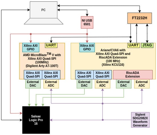
Figure 6.
Test and Benchmark Setup.
- Ariane Xilinx SoC with CVA6 processor and RiscADA Extension as coprocessor and with two Xilinx AXI Quad-SPI (for the time performance comparison between RiscADA and the classical SPI peripheral approach for controlling external DACs and ADCs) deployed on Kintex UltraScale+ XCKU5P-2FFVB676E FPGA on AMD KCU116 development board ([]);
- AMD MicroBlaze V with Xilinx AXI Quad-SPI peripherals deployed on Artix XC7A100TCSG-1 FPGA;
- External DACs: Texas Instruments DAC121S101-Q1 [], 12-bit, 8 µs setting time, 30 MHz maximum operating frequency (used at 25 MHz for the experiments);
- External ADCs: Analog Devices AD7476A [], 12-bit, 20 MHz maximum operating frequency (used at 12.5 MHz for the experiments);
- National Instruments USB-6501 digital data acquisition and control device for stimulating the digital inputs of the MicroBlaze V and Ariane/CVA6 in order to trigger the outputting of an analog value set for the external DACs;
- Siglent SDG2082X Arbitrary Waveform Generator for generating analog signals to be read by the external ADCs;
- FT2232H dual-channel (UART and MPSSE-JTAG) for loading programs on CVA6 program memory via OpenOCD and for UART communication with CVA6;
- Saleae Logic Pro 16—Logic Analyzer and Protocol Decoder for performing time measurements on the whole setup;
- Workstation with AMD Ryzen 9 9950X 16-Core, 96 GB DDR5, 2x1TB NVMe RAID 0 running Ubuntu 22.04.
5.4. Test Scenarios and Results
The tests and performance comparisons implied three scenarios run on all three configurations:
- (C1) AMD MicroBlaze V with Xilinx AXI Quad SPI;
- (C2) Ariane/CVA6 with Xilinx AXI Quad-SPI;
- (C3 )Ariane/CVA6 with RiscADA extension.
The scenarios for tests and comparison are enumerated and described below:
- (M1) Measuring the response time for setting an output analog value on external DACs;
- (M2) Measuring the maximum sample rate for reading the external ADCs (by polling the external ADCs as fast as possible, with respect to the hardware and software limitations); this feature is extremely important when the external ADCs are used in analog signal acquisition systems and the designed system must respect a required sample rate for the requested application class;
- (M3) Measuring the detection time of an over-threshold signal; this feature is crucial for applications where the external ADCs are used for the detection of over-voltage and over-current situations and fault correction actions must be taken within microseconds to prevent damaging the equipment or harming people.
5.4.1. Measuring the Response Time for Setting an Output Analog Value
For this scenario, a preconfigured analog output value is set on the external DACs when devices are triggered by a digital input or an analog value is sent on the same UART line to all the devices for being set on the external DACs. The durations between the arrival of the digital trigger (or the arrival of the bytes on UART) and the moment when the configured output voltage settles are measured with the logic analyzer and noted as setting times of the external DACs.
The measured durations listed in the tables and graphics below represent the averages from 1000 measurements performed; this applies to all the results presented in this paper. The results for this experiment are illustrated in Figure 7.
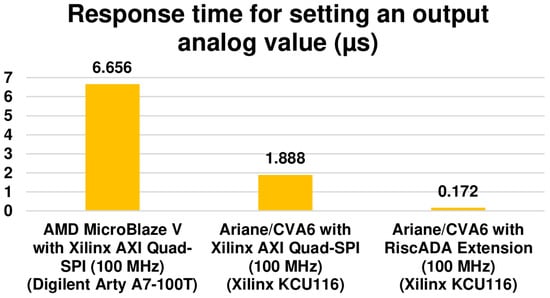
Figure 7.
Response time for setting an output analog value on external DACs.
The results in the chart above (Figure 7) show that by using the CVA6 with RiscADA extension, the setting time of an analog value on external DACs is 38.6× times better than the case of using MicroBlaze V with Xilinx AXI Quad-SPI and 10.9× times better same core, CVA6, but with the same AXI SPI peripheral.
5.4.2. Measuring the Maximum Sample Rate for Reading the External ADCs
For this scenario, the authors measured the maximum achievable sample rate for polling in a loop as fast as possible the external ADCs, using all three available configurations. Since MicroBlaze V and Ariane/CVA6 are performing polling in a loop, the external ADCs by software means, while RiscADA extension always polls the external ADC without the need to execute code, it is expected that the setup using RiscADA will perform better. The results for this test/comparison are depicted below (Figure 8).
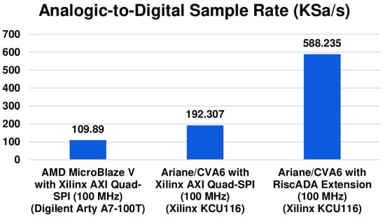
Figure 8.
Maximum sample rates for using the external ADCs.
It can be observed that for using the RiscADA extension with CVA6, the maximum achievable sample rate for using the external ADCs is 5.35× times higher than using the MicroBlaze V with classical AXI SPI peripheral and 3.05× times higher than using the same CVA6 core with the same AXI SPI peripheral.
5.4.3. Measuring the Detection Time of an Over-Threshold Signal
In this scenario, the same threshold and hysteresis values were set on all three configurations, a static analog value just above the threshold plus hysteresis is set on the waveform generator and the durations between the moment the analog signal settles and the moments the over-threshold signal is detected by signal conditioning on all configurations are noted as the over-threshold detection durations. For this experiment, the results are illustrated below in Figure 9.
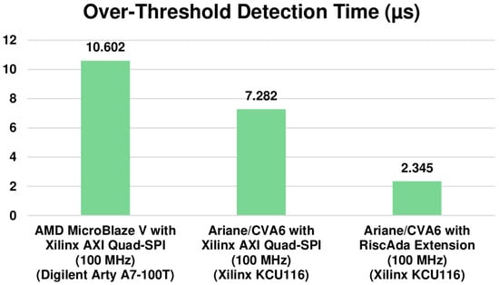
Figure 9.
Over-threshold detection time for the three compared solutions.
The results presented in the third chart (Figure 9) show that an over-threshold signal is detected by CVA6 with RiscADA 4.52× times faster than the MicroBlaze V using Xilinx AXI Quad-SPI peripheral and 3.1× times faster than the same RISC-V core, CVA6, but with Xilinx AXI Quad-SPI peripheral.
5.5. Discussion on Test Results
The better time performances proven by using CVA6 with RiscADA extension in comparison with MicroBlaze V and CVA6 using AXI SPI peripherals for controlling external DACs and external ADCs are the consequence of using domain-specific architecture instead of a generic solution.
In the first place, using the generic AXI SPI peripherals means that control of write and read operations is performed by memory operations, which are slower than directly using the RISC-V register operations, like the RiscADA extension does for controlling the external converters. Figure 10 illustrates that the configurations data or the read data are passing throw many more modules in the case of using AXI SPI peripherals than in the case of using RiscADA.
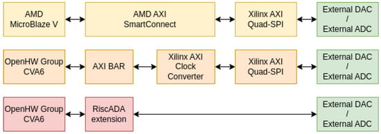
Figure 10.
Block diagrams illustrating the number of modules between the RISC-V cores and the external converters for the three test configurations.
In the second place, the RiscADA extension manages to achieve better sample rate and over-threshold detection times because it does not depend on the code run by the RISC-V core for performing external ADC readings or for performing digital signal conditioning.
The RiscADA extension, which operates in parallel with the CVA6 core, samples in the loop the external ADCs as fast as possible and, once configured with threshold and hysteresis values, will run the digital signal conditioning computations and will also perform basic statistics computation without the intervention of the main core. The feature of getting the timestamp and instant values or any of the statistics or all the statistics in one instruction makes RiscADA ideal for digital acquisition systems.
5.6. FPGA Resource Utilization—Comparison
Since the most common way of controlling high numbers of external DACs and ADCs in analog acquisition and control systems is using FPGAs with soft-cores or custom designs, the authors made a resource utilization comparison between using MicroBlaze V with Xilinx AXI Quad-SPI Peripherals and using CVA6 with RiscADA extension for different numbers of external converters. The synthesis and implementation were performed for a Xilinx XC7A100TCSG-1 FPGA.
The results listed in Table 2 show that using RiscADA uses 2× times fewer LUTs, between 6.1× and 6.5× times fewer LUTRAMs, between 1.58× and 2× times fewer FFs and between 1.7× and 2× times fewer Slices than the case of using AXI SPI peripherals. The RiscADA extension manages to offer much better FPGA resources utilization, even though it not only offers communication with the external converters but also handles tasks like configuring analog output sequences for DACs and computing basic statistics and signal conditioning for the analog inputs sampled by ADCs.

Table 2.
FPGA Resources Utilization—Comparison.
6. Conclusions
The contribution introduced by this paper is an open-source scalable/parametrizable RISC-V extension for optimized control of 12-bit SPI-like external DACs and ADCs, configured and queried by an ISA extension set, integrated as a coprocessor beside CVA6 in Ariane SoC and accessible via a C library with no compiler modifications needed.
The increased time performance and optimized FPGA resources utilization proven by RiscADA are the direct consequences of choosing the domain-specific architecture as a design paradigm. Another reason for performance improvements brought by RiscADA is the placement of this extension near the main core (CVA6), directly exchanging the data with it through the CV-X-IF interface.
The reason for calling the RiscADA extension a hardware accelerator is the capacity to output sequences of multiple analog values and to compute basic statistics over the sampled analog inputs without the need to execute code on main core.
By the optimized access to the external DACs and ADCs offered by RiscADA, the setting time of an analog output is performed 10.9× times faster than using the same CVA6 core with AXI SPI peripherals, the sample rate of analog inputs became 3.05× times higher, and the detection of an over-threshold signal is performed through digital signal conditioning 3.1× times faster.
Even though the CVA6 coprocessor interface (CV-X-IF) does not support memory operations yet, further work includes adding support for DMA data transfer and for the associated interrupts for the purpose of reading the measured values from all external ADCs simultaneously. Another reason for implementing DMA support is configuring multiple analog output values (or sequences) on external DACs in parallel.
These results prove that using the RiscADA extension as a coprocessor for the CVA6 RISC-V core can be chosen as a solution for designing complex analog acquisition and control systems for applications requiring high numbers of analog inputs and outputs. For being used and improved in the spirit of the open-hardware philosophy, the RTL design and the C library were made available in kcu116 branch of the CVA6 fork at https://github.com/cosminandreipopovici/cva6/tree/kcu116 (accessed on 1 July 2025).
Author Contributions
Conceptualization, C.-A.P., A.S., N.-A.B. and V.-I.M.; methodology, C.-A.P., A.S. and V.-I.M.; software, C.-A.P., A.S. and N.-A.B.; validation, C.-A.P., A.S. and N.-A.B.; formal analysis, C.-A.P. and A.S.; investigation, C.-A.P. and N.-A.B.; resources, A.S. and V.-I.M.; data curation, C.-A.P., A.S. and N.-A.B.; writing—original draft preparation, C.-A.P., A.S. and N.-A.B.; writing—review and editing, C.-A.P., A.S., N.-A.B. and V.-I.M.; visualization, C.-A.P.; supervision, A.S. and V.-I.M.; project administration, A.S.; funding acquisition, A.S. All authors have read and agreed to the published version of the manuscript.
Funding
This work was supported in part through the ISOLDE project, nr. 101112274 which is supported by the HORIZON Chips Joint Undertaking and its members Austria, Czechia, France, Germany, Italy, Romania, Spain, Sweden, Switzerland, and in part by a grant of the Romanian Ministry of Research, Innovation and Digitization, CNCS/CCCDI-UEFISCDI, project number PN-IV-P8-8.1-PME-2024-0003.
Institutional Review Board Statement
Not applicable.
Informed Consent Statement
Not applicable.
Data Availability Statement
Dataset available on request from the authors.
Conflicts of Interest
The authors declare no conflicts of interest.
Abbreviations
The following abbreviations are used in this manuscript:
| ADC | Analog-to Digital Converter |
| APB | Advanced Peripheral Bus |
| AXI | Advanced eXtensible Interface |
| CDC | Clock Domain Crossing |
| CMOS | Complementary Metal-Oxide-Semiconductor |
| CPU | Central Processing Unit |
| DAC | Digital-to-Analog Converter |
| DMA | Direct Memory Access |
| DSP | Digital Signal Processor |
| ECU | Electronic Control Unit |
| EU | European Union |
| FF | Flip-Flop (FPGA resource) |
| FPGA | Field-Programmable Gate Array |
| FSM | Finite State Machine |
| GFPLOS | Giga Floating-Point Operations Per Second |
| GPIO | General-Purpose Input/Output |
| HDL | Hardware Description Language |
| HPC | High Performance Computing |
| I2C | Inter-Integrated Circuit |
| IoT | Internet of Things |
| IP | Intelectual Property |
| ISA | Instruction Set Architecture |
| JTAG | Joint Test Action Group |
| JU | Joint Undertaking |
| LUT | Lookup Table |
| MCU | Microcontroller Unit |
| MPSSE | Multi-Protocol Synchronous Serial Engine |
| OCD | On-Chip Debugging |
| PC | Personal Computer |
| PCIe | Peripheral Component Interconnect Express |
| PLIC | Platform-Level Interrupt Controller |
| RAM | Random Access Memory |
| RISC | Reduced Instruction Set Computer |
| RTL | Register-Transfer Level |
| SAR | Successive Approximation Register (ADC type) |
| SoC | System-on-a-Chip |
| SPI | Serial Peripheral Interface |
| SRAM | Static RAM |
| TISAR | Time-Interleaved SAR ADC |
| TOPS | Tera Operations per Second |
| UART | Universal Asynchronous Receiver/Transmitter |
| UVM | Universal Verification Model |
References
- Asanovic, K.; Patterson, D.A. Instruction Sets Should Be Free: The Case for RISC-V; Technical Report, EECS Department, University of California at Berkeley, Technical Report No. UCB/EECS-2014-146; University of California at Berkeley: Berkeley, CA, USA, 2014; Available online: https://www2.eecs.berkeley.edu/Pubs/TechRpts/2014/EECS-2014-146.html (accessed on 14 January 2022).
- European Union. Chips Joint Undertaking. 2023. Available online: https://european-union.europa.eu/institutions-law-budget/institutions-and-bodies/search-all-eu-institutions-and-bodies/chips-joint-undertaking_en (accessed on 11 November 2023).
- European Union. European High Performance Computing Joint Undertaking (EuroHPC JU). 2020. Available online: https://european-union.europa.eu/institutions-law-budget/institutions-and-bodies/search-all-eu-institutions-and-bodies/european-high-performance-computing-joint-undertaking-eurohpc-ju_en (accessed on 14 October 2022).
- The SHD Group. RISC-V Market Report: Application Forecasts in a Heterogeneous World (Abridged Version). San Jose, CA, USA, 2024. Available online: https://theshdgroup.com/wp-content/uploads/2024/01/RISC-V-Market-Analysis-2024-Abridged-Report-2.pdf (accessed on 11 May 2024).
- Holton, T. Digital Signal Processing: Principles and Applications, hardback ed.; Cambridge University Press: Cambridge, UK, 2021; ISBN 9781108418447. [Google Scholar] [CrossRef]
- Zaruba, F.; Benini, L. The Cost of Application-Class Processing: Energy and Performance Analysis of a Linux-Ready 1.7-GHz 64-Bit RISC-V Core in 22-nm FDSOI Technology. IEEE Trans. Very Large Scale Integr. (VLSI) Syst. 2019, 27, 2629–2640. [Google Scholar] [CrossRef]
- OpenHW Group. eXtension Interface—CV-X-IF. OpenHW Group (Working Group of Eclipse Foundation), Brussels, Belgium, 2024. Available online: https://docs.openhwgroup.org/projects/openhw-group-core-v-xif/en/latest/x_ext.html#cv-x-if (accessed on 1 November 2024).
- Patterson, D.A.; Hennessy, J.L. Computer Organization and Design: The Hardware/Software Interface, 1st ed.; Morgan Kaufmann Publishers: Cambridge, MA, USA, 2017; ISBN 9780128122754. [Google Scholar]
- Duran, C.; Rueda, D.L.; Castillo, G.; Agudelo, A.; Rojas, C.; Chaparro, L.; Hurtado, H.; Romero, J.; Ramirez, W.; Gomez, H.; et al. A 32-bit RISC-V AXI4-lite bus-based microcontroller with 10-bit SAR ADC. In Proceedings of the IEEE 7th Latin American Symposium on Circuits & Systems (LASCAS), Florianopolis, Brazil, 28 February–2 March 2016. [Google Scholar] [CrossRef]
- Križan, M.; Budanović, I.; Čoti, M.; Kundrata, J.; Čeperić, V.; Mandić, T. Design and Verification Challenges in SoC Integration of PicoRV32 RISC-V with Sigma-Delta ADC. In Proceedings of the 47th MIPRO ICT and Electronics Convention (MIPRO), Opatija, Croatia, 20–24 May 2024; pp. 1344–1349. [Google Scholar] [CrossRef]
- Bailey, S.; Han, J.; Rigge, P.; Lin, R.; Chang, E.; Mao, H. A Generated Multirate Signal Analysis RISC-V SoC in 16nm FinFET. In Proceedings of the 2018 IEEE Asian Solid-State Circuits Conference (A-SSCC), Tainan, Taiwan, 5–7 November 2018; pp. 285–288. [Google Scholar] [CrossRef]
- Bailey, S.; Rigge, P.; Han, J.; Lin, R.; Chang, E. A Mixed-Signal RISC-V Signal Analysis SoC Generator with a 16-nm FinFET Instance. IEEE J. Solid-State Circuits 2019, 54, 2786–2801. [Google Scholar] [CrossRef]
- Cabo, G.; Candón, G.; Carril, X.; Doblas, M.; Domínguez, M.; González, A. DVINO: A RISC-V Vector Processor Implemented in 65nm Technology. In Proceedings of the 37th Conference on Design of Circuits and Integrated Systems (DCIS 2022), Pamplona, Spain, 16–18 November 2022; p. 9970128. [Google Scholar] [CrossRef]
- Du, L.; Gohil, S.; Ma, M.; Nguyen, B.M.; Sasic, M.; Yun, J. RISC-V Microcontroller and Encryption Accelerator with Integrated ADC, DAC and On-Chip References. Technical Report, University of Illinois, Urbana-Champaign, Dept. of Electrical & Computer Engineering, 2024. ECE 498HK Project Report. Available online: https://courses.grainger.illinois.edu/ece498hk/fa2024/data/projects/ECE498HK-G3.pdf (accessed on 9 January 2025).
- Zhong, X.; Ma, S.L.; Chou, H.-F. A RISC-V SoC for Terahertz IoT Devices: Implementation and Design Challenges. arXiv 2024, arXiv:2401.14620. [Google Scholar] [CrossRef]
- Renesas Electronics Corporation. RISC-V A/D Converter (Scan Mode) Application Note, R01AN7170EJ0100 Rev.1.00. Application Note R01AN7170EJ0100 Rev.1.00, Renesas Electronics Corporation, Koto City, Tokyo, Japan, 2024. Published 18 March 2024. Available online: https://www.renesas.com/ja/document/apn/risc-v-ad-converter-scan-mode-application-note (accessed on 17 December 2024).
- Renesas Electronics Corporation. R9A02G021 Datasheet (32-Bit MCU Based on RISC-V). Datasheet R01DS0422EJ0110 Rev. 1.10, Renesas Electronics Corporation, Koto City, Tokyo, Japan, 2024. Published 29 February 2024. Available online: https://www.renesas.com/en/document/dst/r9a02g021-datasheet (accessed on 17 December 2024).
- GigaDevice Semiconductor Inc. GD32VF103 Series MCUs. Haidian District, Beijing, China, 2025. Available online: https://www.gigadevice.com/product/mcu/main-stream-mcus/gd32vf103-series (accessed on 14 June 2025).
- Dolmeta, A.; Martina, M.; Masera, G. ATHOS: A Hybrid Accelerator for PQC CRYSTALS-Algorithms Exploiting New CV-X-IF Interface. IEEE Access 2024, 12, 182340–182352. [Google Scholar] [CrossRef]
- OpenHW Group. CORE-V CV32E40X–4-Stage, In-Order 32-Bit RISC-V Core: User Manual, Version 0.10.0. Technical Report v0.10.0, OpenHW Group (Working Group of Eclipse Foundation), Brussels, Belgium, 2023. Solderpad Hardware License 0.51. Available online: https://docs.openhwgroup.org/projects/cv32e40x-user-manual/en/latest (accessed on 3 November 2024).
- Hepola, K.; Arachchige, T.R.; Multanen, J.; Jääskeläinen, P. Fully Automatic Compiler Retargeting and CV-X-IF Hardware Interface Generation for RISC-V Custom Instructions. In Proceedings of the 2024 IEEE Nordic Circuits and Systems Conference (NorCAS), Lund, Sweden, 29–30 October 2024; pp. 1–7. [Google Scholar] [CrossRef]
- RISC-V International. The RISC-V Instruction Set Manual. RISC-V International Association, Zürich, Switzerland, 2019. Available online: https://github.com/riscv/riscv-isa-manual/releases/download/Ratified-IMAFDQC/riscv-spec-20191213.pdf (accessed on 7 January 2023).
- AMD Inc. KCU116 Board User Guide (UG1239), Revision 1.3 ed.; Santa Clara, CA, USA, 2023. Describes the Features of the KCU116 Evaluation Board for the Kintex UltraScale+ XCKU5P-L2FFVB676E FPGA. Available online: https://docs.amd.com/v/u/en-US/ug1239-kcu116-eval-bd (accessed on 18 November 2024).
- GNU Project. RISC-V Operand Modifiers. GNU Compiler Collection (GCC), GNU Project supported by Free Software Foundation, 2025. Part of the GCC Documentation on Extended Asm. Available online: https://gcc.gnu.org/onlinedocs/gcc/Extended-Asm.html#RISC-V-Operand-Modifiers (accessed on 11 November 2024).
- OpenHW Group. CV32E40P User Manual; OpenHW Group (Working Group of Eclipse Foundation): Brussels, Belgium, 2023; Available online: https://docs.openhwgroup.org/projects/cv32e40p-user-manual/en/latest/ (accessed on 14 October 2024).
- OpenHW Group. CORE-V MCU Overview; OpenHW Group (Working Group of Eclipse Foundation): Brussels, Belgium, 2023; Available online: https://docs.openhwgroup.org/projects/core-v-mcu/doc-src/overview.html (accessed on 14 October 2024).
- OpenHW Group. Micro-DMA Subsystem; OpenHW Group (Working Group of Eclipse Foundation): Brussels, Belgium, 2022; Available online: https://docs.openhwgroup.org/projects/core-v-mcu/doc-src/udma_subsystem.html (accessed on 14 October 2024).
- Snyder, W.; Wasson, P.; Galbi, D. Verilator; 2015. Available online: https://github.com/verilator/verilator (accessed on 21 May 2023).
- AMD Inc. Vivado Design Suite User Guide: Logic Simulation; Santa Clara, CA, USA, 2024. UG900 (v2024.2). Available online: https://docs.amd.com/r/en-US/ug900-vivado-logic-simulation (accessed on 16 May 2025).
- Texas Instruments. DAC121S101/-Q1 12-Bit Micro Power, RRO Digital-to-Analog Converter. Dallas, TX, USA, 2015. Available online: https://www.ti.com/lit/ds/symlink/dac121s101.pdf (accessed on 7 January 2025).
- Analog Devices. AD7476A/AD7477A/AD7478A—2.35 V to 5.25 V, 1 MSPS, 12-/10-/8-Bit ADCs in 6-Lead SC70. Wilmington, MA, USA, 2016. Available online: https://www.analog.com/media/en/technical-documentation/data-sheets/ad7476a_7477a_7478a.pdf (accessed on 7 June 2025).
Disclaimer/Publisher’s Note: The statements, opinions and data contained in all publications are solely those of the individual author(s) and contributor(s) and not of MDPI and/or the editor(s). MDPI and/or the editor(s) disclaim responsibility for any injury to people or property resulting from any ideas, methods, instructions or products referred to in the content. |
© 2025 by the authors. Licensee MDPI, Basel, Switzerland. This article is an open access article distributed under the terms and conditions of the Creative Commons Attribution (CC BY) license (https://creativecommons.org/licenses/by/4.0/).