Abstract
To enhance the rapid and stable tracking of a specified trajectory by quadcopter drones, while ensuring a degree of resistance to external wind disturbances, this paper proposes an integrated control strategy that combines an optimization algorithm and fuzzy control. In this system, both the position and attitude loops utilize second-order Linear Active Disturbance Rejection Control (LADRC) controllers, supplemented by fuzzy controllers. These controllers have been optimized using a modified crayfish optimization algorithm (MCOA), resulting in a dual-closed-loop control system. In comparisons with both the dual-closed-loop LADRC controller and the dual-closed-loop fuzzy control LADRC controller, the proposed method reduces the rise time by 52.87% in the X-channel under wind-free conditions, reduces the maximum trajectory tracking error by 86.37% under wind-disturbed conditions, and reduces the ITAE exponent by 66.2%, which demonstrates that the newly designed system delivers excellent tracking speed and accuracy along the specified trajectory. Furthermore, it remains effective even in the presence of external disturbances, it can reliably maintain the target position and the attitude angle, demonstrating strong resistance to interference and stability.
1. Introduction
Small quadcopter drones have gained widespread application in various fields in recent years due to their simple structure; flexible control; low cost; and strong capabilities for vertical takeoff, landing, and hovering. For example, they are extensively used in wildfire detection [], fault diagnosis [], pesticide spraying [], and forestry photography []. Therefore, how to enhance the controllability, high precision, and anti-interference capabilities of small quadcopter UAVs under complex wind conditions has become a very worthwhile study topic in the current research field of small quadcopter UAVs [,].
The PID controller is the most commonly used and classic type of feedback controller in industrial control systems and is widely applied in small quadcopter drones. It dynamically corrects control errors through proportional (P), integral (I), and derivative (D) adjustments, enabling the system output to quickly and stably track the desired value. In reference [], fuzzy control is concomitant with the PID controller to dynamically adjust the controller parameters. The simulation results indicate that the fuzzy-controlled PID controller offers an improved tracking performance and reduced overshoot compared to the standard PID controller. Reference [] proposes novel fuzzy PID surface super-twisted sliding mode control. The proposed SMC controller employs a super-twisted algorithm and utilizes fuzzy control to adjust the controller parameters. The results demonstrate a superior tracking performance and disturbance rejection capability. Park et al. [] combined a multi-layer fuzzy neural network with PID control using the gradient descent method to derive parameter update laws and establish a multi-layer structure for online adjustment of PID controller parameters. The simulation results demonstrated its excellent control performance. Alrubyli et al. [] combined reinforcement learning’s Q-learning with a PID controller, utilizing its unique reward mechanism to adjust the PID parameters, enabling faster and smoother flight of quadcopter drones. Reference [] combines fuzzy logic control long- and short-term memory networks to form a control framework that is both predictive and adaptive. The integrated co-optimization of prediction and control is realized, providing a smart energy management framework with practical guidance for microgrid systems.
Active Disturbance Rejection Control (ADRC) is an advanced control method that does not require precise models and has strong robustness. It was first proposed by Professor Han Jingqing [] and is a robust control method based on the observer concept that does not depend on precise models. Compared with traditional PID, ADRC can effectively cope with system uncertainties and external disturbances and is particularly suitable for controlling nonlinear, strongly coupled, and difficult-to-model objects such as quadcopter drones. Reference [] combines the ADRC controller with a quadcopter drone, establishing an ADRC control loop in the attitude loop. The simulation results demonstrate that the ADRC controller achieves an excellent performance in attitude control of quadcopter UAVs. Cheng et al. [] combined the quantitative feedback theory with the ADRC controller to form an ADRC controller with generalized predictive control (ADRC-GPC), which exhibits stronger robustness and a more dynamic performance than the traditional ADRC controller. Reference [] combines the ADRC controller with a fast terminal unidirectional sliding mode (FTUSMC) attitude controller, deriving the control law via the FTUSMC to accelerating system convergence and bolstering overall robustness. The simulation results indicate that the proposed control strategy can effectively and precisely track the desired signal trajectory. Reference [] proposes a control strategy combining LQR and LADRC using LQR to adjust the relationship between the fast response of the controlled object’s output and the amplitude of its input.
Linear Active Disturbance Rejection Control (LADRC) is a simplified implementation of ADRC proposed by Professor Gao Zhiqiang []. LADRC retains the core principles of ADRC (disturbance estimation and compensation), but replaces the nonlinear functions (such as the fal function) with linear structures, making it more suitable for engineering applications and rapid implementation. Wang et al. [] combined the LADRC controller with sliding mode control (SMC) to form a mass-adaptive control strategy. SMC improves the controller’s robustness and resolves the accuracy issues caused by the bandwidth limitations of LADRC. The simulation results show that the designed control strategy adjusts the controller parameters using BP to modify the bandwidth value of LESO, while incorporating adaptive control to adjust the LESO observation error and PD gain magnitude, resulting in reduced overshoot and a faster response speed. Gao et al. [] proposed a control strategy combining a BP neural network with adaptive LADRC. They optimized the adjustment of LADRC.
Reinforcement learning (RL) is an important machine learning method in Artificial Intelligence (AI), which enables an agent to learn the optimal policy by interacting with the environment and learning through trial and error to maximize long-term returns. A study [] controls a quadrotor by using an RL-trained neural network that remains stable under complex tasks. Lambert et al. [] realized low-level control of a quadrotor by building a model-based RL with a small amount of real flight data. Stabilized hovering control of Crazyflie without internal PID and without prior knowledge was achieved. Another study [] proposes a robust control strategy based on reinforcement learning, combining the RISE controller and the OADC (One-Actor Dual-Critic) learning framework. The jitter problem of traditional RISE is solved. RL training is accelerated by model knowledge, while retaining the flexibility and adaptability of RL. A different study [] establishes a disturbance-compensated reinforcement learning (DCRL) framework, which improves the robustness of the system by combining a reinforcement learning controller and a disturbance observer to estimate and compensate for external disturbances in real time. The experimental results show that DCRL significantly outperforms the traditional RL controller in wind-disturbed environments.
Traditional controller parameter tuning largely relies on human experience, which often leads to conflicts between multiple objectives, such as the difficulty of balancing a fast response and high stability. In recent years, the application of intelligent optimization algorithms has become increasingly widespread. These algorithms play a crucial role in controller parameter tuning by enabling automatic search, global optimization, and strong adaptability, effectively overcoming the issues of low efficiency, strong reliance on experience, and difficulty in handling complex systems associated with the traditional manual tuning methods. Reference [] employs a particle swarm optimization algorithm to adjust the PID parameters, setting the PSO conditions to search for the initial PID controller parameters. The results indicate that the controller parameters selected through PSO optimization yield a better performance. Reference [] proposes an explosion-based optimization algorithm (REA) applied to PD-LQR controllers. This optimization algorithm is based on random fragmentation and dispersion generated during explosions. Through comparison with other optimization algorithms, it demonstrates that this optimization algorithm can converge to the global optimal solution more quickly. Reference [] proposes a method combining the cuckoo search algorithm (CSA) with a PID controller. By comparing it with the PSO-PID control strategy, the results show that although CSA requires more iterations, the PID controller adjusted by CSA has a faster response speed. Another study [] proposes an improved genetic optimization algorithm (IGA) to enhance population genetic diversity. The improved IGA is combined with an ADRC controller, and by adjusting the ADRC controller parameters, the control performance of the quadcopter drone in terms of altitude and attitude is improved.
Although LADRC has demonstrated robust performance in quadrotor control, there is still a lack of research on combining LADRC with intelligent optimization algorithms and fuzzy logic for robust and adaptive control during wind disturbances. To address this gap and enhance the quadrotor’s resilience against wind disturbances, this study aims to improve the efficiency of initial parameter tuning of the controller and improve the overall control performance of the quadcopter drone in conditions of wind disturbance. Based on the quadcopter drone model, a dual-loop control strategy is established. Both the inner and outer loops adopt the LADRC control strategy with MCOA-tuned parameters and additional fuzzy control. The optimal initial parameters for LADRC are selected using the MCOA, and the LADRC parameters are dynamically adjusted via fuzzy control to adapt to environmental changes. Through simulation experiments, the novel control strategy proposed in this paper is compared to the dual-loop LADRC control strategy and the dual-loop LADRC control strategy with fuzzy control under both wind-free and wind-disturbed conditions. The results demonstrate that the proposed control strategy offers an improved performance in trajectory tracking and exhibits superior control abilities when faced with wind disturbances.
2. Quadrotor Modeling
The quadcopter drone in this paper adopts an X-type model, consisting of four rotors and an X-shaped fuselage. The rotors rotate in the same direction relative to the center of symmetry of the aircraft. Simultaneously, it is assumed that the drone has a rigid structure, with its center of gravity aligned at its midpoint. The coordinate system of the quadcopter drone is defined as illustrated in Figure 1.
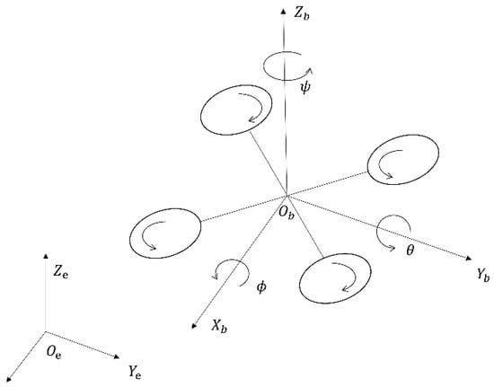
Figure 1.
Diagram of quadrotor coordinate structure.
Quadcopter drones have three position channels and three attitude channels. By introducing the relationship between the ground coordinate system and the aircraft coordinate system, a rotation matrix is introduced:
where is for and is for .
The total lift of the drone is expressed as follows:
where
represent four-rotor lift.
The four control signals of the quadcopter drone system and their relationship to the lift of the four rotors are given as follows:
Using Newton’s and Euler’s laws of motion, kinematic equations for a quadcopter drone are given as follows:
where is moments of inertia, is wheelbases; and , represent drag coefficients.
In this study, several idealized assumptions were made in quadrotor UAV dynamics to reduce model complexity and focus on verifying the proposed control strategy. Specifically, air resistance and wind disturbances were initially neglected in the modeling phase, the UAV structure was assumed to be perfectly rigid, and the thrust and torque outputs from the propellers were considered linearly controllable without actuator delays or saturation effects. These assumptions are reasonable for small-scale UAVs operating in low-speed, indoor environments, where aerodynamic and structural effects are minimal. However, in real-world scenarios, these simplifications may lead to discrepancies between the simulation and the actual performance. Some potential limitations include degraded control accuracy, increased response delay, reduced robustness under external disturbances, and mismatches between the simulation results and the physical tests due to unmodeled dynamics. Future work will aim to incorporate more realistic aerodynamic and environmental factors to further validate the controller’s performance in practical applications.
3. Controller Design
Given the susceptibility of small quadcopter drones to external influences, the controller employs a second-order LADRC controller, supplemented by fuzzy control and the MCOA. The initial parameters of LADRC are obtained with the help of MCOA selection, while fuzzy control dynamically adjusts the parameters of the LADRC controller to enhance system robustness. The control structure is shown in Figure 2.
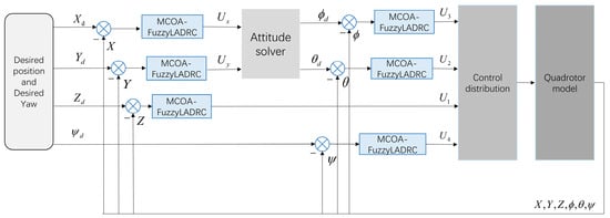
Figure 2.
Overall block diagram of control system.
3.1. Modified Crayfish Optimization Algorithm
The crayfish optimization algorithm (COA) was introduced by Heming Jia et al. in 2023 []. The COA is based on three behaviors of freshwater shrimp and crabs: summer avoidance, cave competition, and foraging. It uses “temperature” as a control factor to regulate exploration and exploitation, and for the first time introduces shrimp and crab ecological behaviors into the framework of swarm intelligence optimization. However, due to the COA’s tendency to become stuck in local optima and experience reduced search efficiency in later stages, Heming Jia et al. introduced a modified crayfish optimization algorithm (MCOA) in 2024 []. This algorithm features an environmental update mechanism and a ghost adversarial learning strategy, which enhance its ability to escape local optima and provide efficient solutions for complex optimization problems.
The first step is the initialization phase:
where between [0, 1], , represent the upper and lower bounds of the search space.
At the same time, one can calculate the temperature as follows:
The second step is to enter the main loop phase. At this point, the environmental parameters are updated, and the position of each individual is updated. Discrete water quality factors are obtained through local environmental assessment.
When the water quality factor , it updates the current location:
where is a random position, is the adaptive water flow coefficient, and is a random position between the optimal position and the current position. represents the movement direction of the crayfish. The calculation formulas for and are as follows:
When is between [0,1], the water flow coefficient .
When the water quality factor , the original COA position is updated and divided into a high-temperature stage and a low-temperature stage.
For the high-temperature stage (), if , the position update formula is as follows:
where is a decreasing curve, and denotes the number of iterations.
, represent the optimal position of the current individual and the optimal position of the group, respectively.
If , then the position update formula is as follows:
represents a random individual crayfish:
During the low-temperature phase (), feed intake is calculated first:
where is the optimal temperature, and and are parameters that control changes in food intake at different temperatures.
Then, we proceed to food size determination:
where represents the food factor constant 3, represents the fitness value of the th crayfish, and represents the fitness value of the food location of the th crayfish.
If the food size is , then the current position is calculated as follows:
where
If the food size is , then the current position is calculated as follows:
The positions of each crayfish are updated using the above method, and then ghost reverse learning is introduced. For each individual , let the current candidate position be and the old position be :
The amplification factor is then calculated:
where is for the current iteration and is for the total iteration.
Opposing solutions are generated:
By comparing the fitness function values and , the optimal solution for the current iteration is selected. Then, the global optimal solution is updated, and are updated, and the global optimal solution is output when the maximum number of iterations is reached.
To validate the superiority of the selected optimization algorithms in parameter selection for the LADRC controller, a step response with an input of 1 is established. Taking the pitch channel transfer function as an example, the LADRC controller is employed. As shown in Figure 3, by comparing the response performances of the LADRC controller adjusted by the three optimization algorithms (PSO, GAPSO, and MCOA) and the LADRC controller without optimization algorithm adjustment to the step response, it can be concluded that LADRC optimized by the three optimization algorithms reaches stability at approximately the same time, but LADRC optimized by the MCOA has a smaller overshoot.
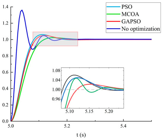
Figure 3.
Comparison of effects of various optimization algorithms.
3.2. Fuzzy Control Design
Fuzzy control is an intelligent control method based on fuzzy logic, suitable for systems with unknown or imprecise mathematical models, high nonlinearity, and strong disturbances. It is widely applied in fields such as unmanned aerial vehicle control, robotics, and industrial automation. Its core principle is to utilize human experiential knowledge to design control strategies through linguistic rule inference. The controller translates input variables, such as the error and its rate of change, into linguistic variables and infers the control output based on a fuzzy rule base.
A fuzzy controller typically consists of four parts: fuzzification, establishment of a fuzzy rule base, fuzzy reasoning, and defuzzification. By inputting the error and error rate of each channel, the adjusted is output to the corresponding control module according to the LADRC fuzzy rule table and iterated with the control parameters of the previous stage to obtain new controller parameters, thereby achieving real-time adjustment of the LADRC controller parameters. The parameter adjustment formula is as follows:
In this formula, is the controller parameter of the previous stage, and is the output quantity of fuzzy control.
The fuzzy controller uses the tracking error and its derivative as inputs and generates an adjustment coefficient as the output. This coefficient is used to modify the LADRC gain parameters in real time. The core idea is that large errors and rapid changes in the error indicate the need for stronger control effort, hence larger gain adjustments. Small errors and slow variations suggest the system is near stability, so minimal or no adjustment is needed to avoid overshooting or instability. Intermediate conditions lead to moderate gain tuning to balance speed and precision.
The fuzzy control rules in Table 1 were designed based on conventional control heuristics and qualitative expert knowledge. Each rule considers how the combination of current error and its rate of change should influence the controller’s aggressiveness.

Table 1.
Fuzzy rules.
Membership functions of the inputs , are shown in Figure 4. The output affiliation function graph is shown in Figure 5.
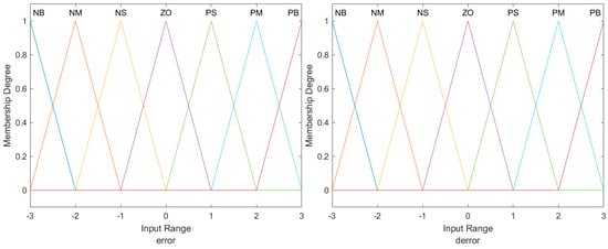
Figure 4.
Membership functions.
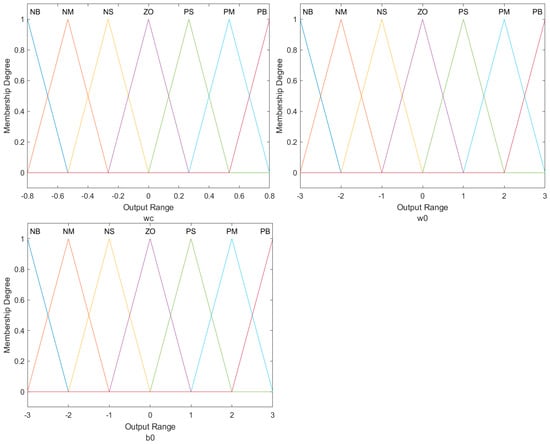
Figure 5.
membership function.
3.3. Position and Attitude Controller Design
Since LADRC is commonly used to handle external disturbances and system modeling uncertainties, it has strong robustness. Therefore, both the position loop and attitude loop controllers in this paper adopt LADRC controllers. Based on this, the initial parameters of the controller are adjusted by the MCOA, while fuzzy control is added externally to dynamically adjust the parameters. This forms an MCOA–fuzzy hybrid control strategy. The control structure is shown in Figure 6.
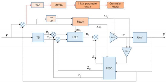
Figure 6.
Structure of control system.
The Linear Expanded Observer (LESO) estimates the system state and disturbance by expanding the total disturbance of the system into a new state variable. For a second-order system:
where is the total system disturbance (including model uncertainty and external disturbances), and is the control gain.
To design LESO, the extended system state variables are defined as follows:
Then, the state space equation of the system is given as follows:
Let
To observe , construct a linear expansion observer to estimate them:
where is the state estimation vector, is the output matrix, and is the observer error gain.
To eliminate disturbances, establish a disturbance compensation formula:
Calculate control quantities using LESO-estimated states:
where is the virtual control quantity calculated by LSEF, and the controller gains , , and are controller coefficients.
3.4. Stability Analysis
To assess the stability of the controller, the roll channel within the attitude control loop is selected as a representative case study. In the UAV model, both internal coupling effects and external disturbances are collectively regarded as total system perturbations. Accordingly, the dynamic behavior of the roll channel can be characterized as follows:
Here, denotes the overall perturbation affecting the roll channel, while represents roll acceleration, which is obtained by applying the Laplace transform to Equations (26)–(31).
Here, denotes the desired roll angle, which is obtained by substituting Equation (34) into Equation (35):
Assuming that LESO can accurately estimate perturbation, Equation (33) is derived by applying the Laplace transform to the original system equation:
This expression characterizes the relationship between the actual roll angle output and its desired reference value:
According to the Routh–Hurwitz stability criterion, the system is deemed stable if conditions and are sufficiently satisfied, as this ensures that all the closed-loop poles lie in the left half of the complex plane. Given that is a controller parameter and is positive, it can be concluded that the closed-loop system is indeed stable.
4. Simulation and Discussion
The text-designed hybrid control strategy (MCOAFuzzyLADRC) was compared with the dual-loop LADRC control strategy and the dual-loop FuzzyLADRC control strategy using the same quadcopter drone model and with the same desired position, attitude, and disturbance signal conditions, demonstrating that the designed hybrid control strategy has a better control performance and wind disturbance resistance.
To facilitate analysis, the time-weighted integral absolute error (ITAE) is introduced as a controller evaluation metric with the following formula:
The parameters relevant to the quadrotor UAV are listed in Table 2, and the controller parameters are shown in Table 3.

Table 2.
Parameters of UAV.

Table 3.
Parameters of controller.
4.1. Simulation of Signal Tracking
The quadcopter is initialized at the origin with an initial position of (0, 0, 0) and an initial attitude angle of (0, 0, 0). Given a step signal with a fixed value of 2 for the desired X and Y positions of the quadcopter drone, a step signal with a fixed value of 1 for the desired Z position, and a desired yaw angle of 0, the simulation results are presented in Figure 7 and Figure 8.
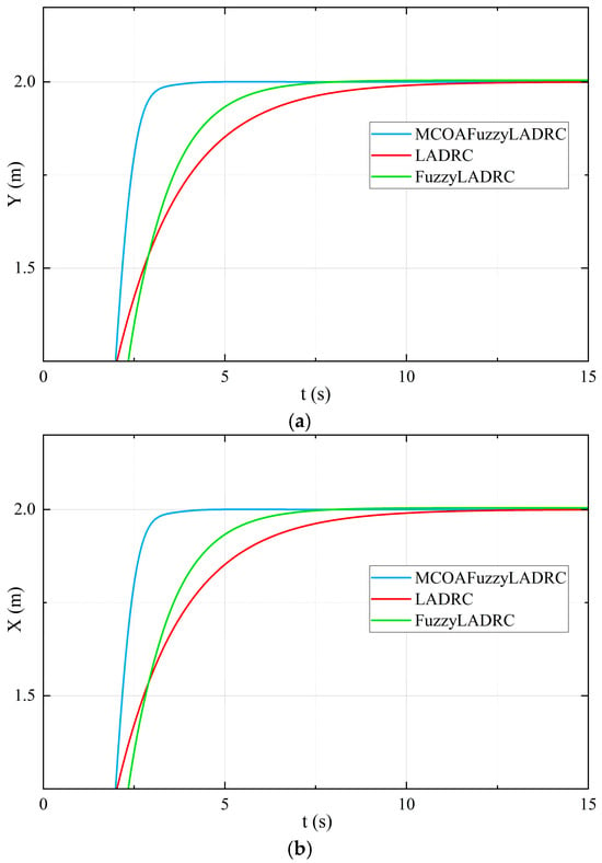
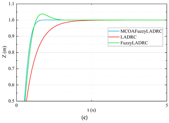
Figure 7.
Comparison of simulation results. (a) X; (b) Y; (c) Z.
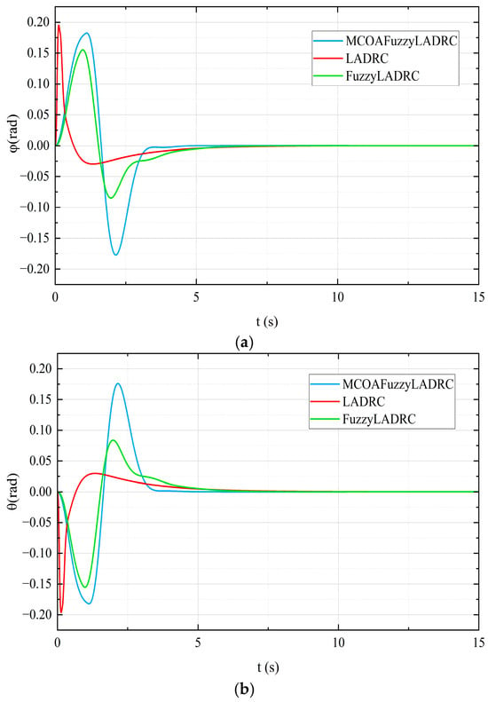
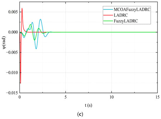
Figure 8.
Comparison of simulation results. (a) Roll; (b) pitch; (c) yaw.
For ease of analysis, the rise time, i.e., the time required to reach the expected value, is recorded in Table 4.

Table 4.
Ascending time of each channel.
Analysis of these figures and tables shows that the MCOAFuzzyLADRC control strategy at the position loop reduces the rise time in the X and Y directions by 64.7% and 48.2%, respectively, compared to the dual-loop LADRC and FuzzyLADRC control strategies. In the Z direction, the rise time is reduced by 73.1% and 31.7%, respectively.
The ITAE values for each channel are summarized in Table 5. As evidenced by the data, the MCOAFuzzyLADRC controller achieves lower ITAE values, indicating faster convergence rates and reduced overshoot relative to the other two controllers. These results demonstrate that the proposed composite control strategy delivers a superior tracking performance for step input signals.

Table 5.
Comparison of ITAE with different control strategies.
4.2. Additional Wind Disturbance Simulation
The initial position of the quadcopter drone is (0, 0, 0), and the initial attitude angle is (0, 0, 0). The given stationary flight trajectory of the quadcopter drone is shown in Table 6. A half-period sine gust with an amplitude of three and a time-varying wind with an amplitude of one were introduced as external disturbances for the drone. The wind model is shown in the Figure 9, and the time of wind disturbance introduction is shown in Table 7. The effectiveness of the designed controller was validated through fixed-point flight simulation experiments.

Table 6.
Hovering trajectory at fixed point.
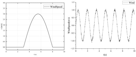
Figure 9.
Wind disturbance model.

Table 7.
Wind disturbance schedule.
As shown in Figure 10, the LADRC strategy optimized by the MCOA and supplemented with fuzzy control exhibits a faster convergence speed and stronger wind disturbance resistance compared to the double-loop LADRC control strategy, which has the slowest tracking speed and is most affected by disturbances. The double-loop LADRC control strategy supplemented with fuzzy control has a control performance that is intermediate between the two. As shown in Figure 11, due to the fast-tracking speed of the new controller, the rotor motor changes more frequently, resulting in larger changes in attitude angle, but it quickly converges to a stable state. Table 8 and Table 9 show the maximum overshoot of each channel under two wind disturbance conditions. From these tables, it can be seen that under gusty wind conditions, the maximum overshoot of the MCOAFuzzyLADRC control strategy in the X and Y channels is reduced by approximately 52.87% and 12.76%, respectively, compared to the dual-closed-loop LADRC and fuzzy LADRC control strategies. In the Z channel, the maximum overshoot is reduced by approximately 51.35% and 36.4%, respectively. Under time-varying wind conditions, the MCOAFuzzyLADRC control strategy reduces the maximum overshoot of the X and Y channels by approximately 86.37% and 69.68%, respectively, compared to the dual-loop LADRC and FuzzyLADRC control strategies.
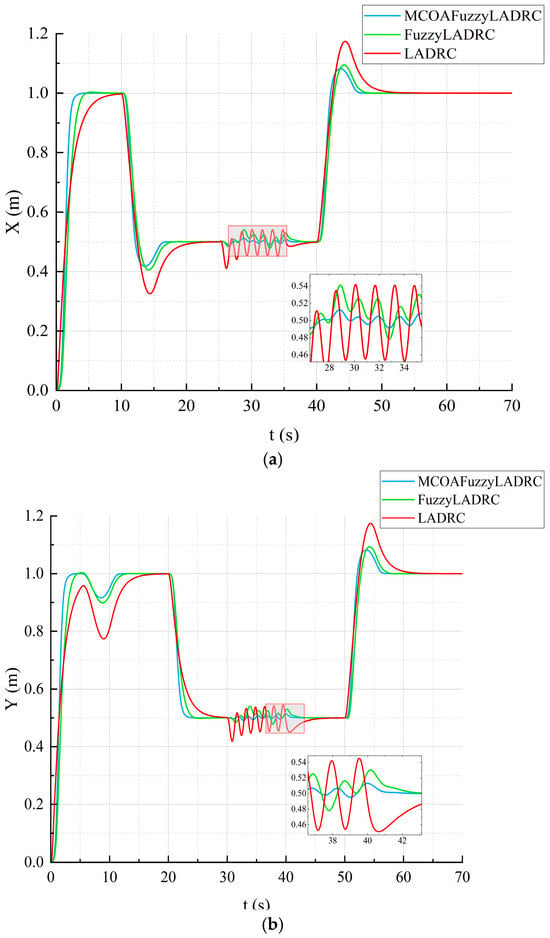
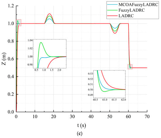
Figure 10.
Comparison of simulation results. (a) X; (b) Y; (c) Z.
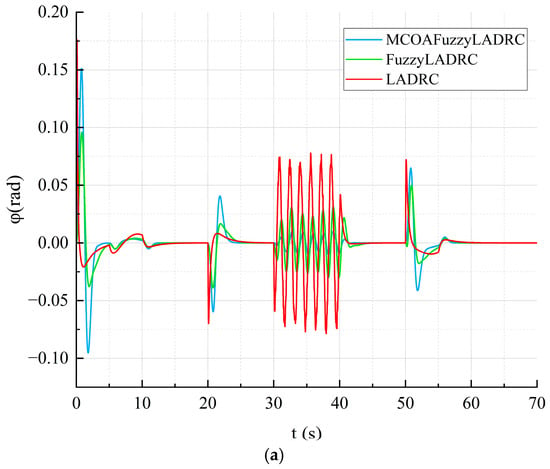
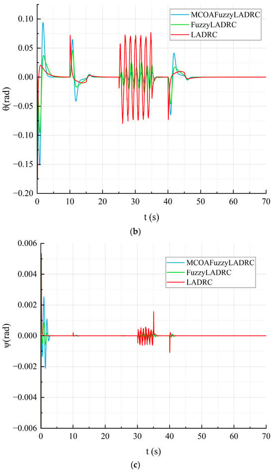
Figure 11.
Comparison of simulation results. (a) Roll; (b) pitch; (c) yaw.

Table 8.
Maximum overshoot in each channel under gusty conditions.

Table 9.
Maximum overshoot in each channel under time-varying wind conditions.
Table 10 summarizes the ITAE values for each channel. As evidenced by the data, the MCOAFuzzyLADRC control strategy proposed in this paper exhibits lower ITAE values, indicating faster convergence rates and enhanced robustness. These results further confirm that the novel control strategy designed herein offers superior wind disturbance rejection capabilities and facilitates quicker system stabilization.

Table 10.
Comparison of ITAE with different control strategies.
5. Conclusions
This article addresses the nonlinear, highly coupled, and under-actuated characteristics of quadrotor flight control systems, as well as their susceptibility to external disturbances that can affect flight performance. We propose a novel control strategy aimed at enhancing the robustness of the control system against external disturbances, while optimizing flight performance. This specific research focuses on the following aspects:
- We establish a flight dynamics model for the quadrotor drone, delineating the relationship between various channels and the controller. Based on this, we develop an inner and outer loop control structure, with both loops employing the LADRC strategy enhanced by MCOA-optimized fuzzy control.
- To address the complexity and difficulty in achieving optimal parameters for the LADRC controller, we propose a method using the MCOA to select the initial parameters for the LADRC controller. The MCOA incorporates an environmental updating mechanism and a ghost cooperative learning strategy that improve the ability to escape local optima, thereby facilitating the selection of optimal parameters for the controller.
- In response to external disturbances, we introduce a fuzzy control algorithm based on the existing controller. By modeling fuzzy rules, we achieve real-time dynamic adjustments to the LADRC controller parameters, ensuring that the quadrotor maintains stable control in changing environments despite disturbances.
- The proposed optimization algorithm and integration of fuzzy control were validated through simulations. However, discrepancies may arise in real-world applications due to factors like sensor noise and uncertainties in modeling. Future work will focus on implementing this control strategy in actual flight tests to robustly verify its superiority.
Author Contributions
Conceptualization, K.L., Y.B. and G.W.; methodology, K.L., Y.B.; software, K.L., Y.B.; validation, K.L., Y.B.; writing—original draft preparation, K.L.; writing—review and editing, Y.B. and G.W. All authors have read and agreed to the published version of the manuscript.
Funding
Jiangsu Province Natural Science Foundation (BK20130782) of China.
Data Availability Statement
The data are contained within this article.
Conflicts of Interest
Author Guangzhao Wang was employed by the company Hangzhou Zhiyuan Research Institute Co. The remaining authors declare that the research was conducted in the absence of any commercial or financial relationships that could be construed as a potential conflict of interest.
References
- Mawanza, J.; Agee, J.; Bhero, E. Finite-time Control for a Quadcopter UAV in the Application of Wildfire Monitoring. IET Control Theory Appl. 2024, 18, 1540–1558. [Google Scholar] [CrossRef]
- Lai, W.-H.; Tsai, S.-T.; Cheng, D.-L.; Liang, Y.-R. Application of Wavelet Scattering and Machine Learning on Structural Health Diagnosis for Quadcopter. Appl. Sci. 2021, 11, 10297. [Google Scholar] [CrossRef]
- Souvanhnakhoomman, S. Review on Application of Drone in Spraying Pesticides and Fertilizers. 2024. Available online: https://arxiv.org/pdf/2402.00020 (accessed on 19 July 2025).
- Yadav, Y.; Kushwaha, S.K.P.; Mokros, M.; Chudá, J.; Pondelík, M. Integration of Iphone Lidar with Quadcopter and Fixed Wing UAV Photogrammetry for the Forestry Applications. Int. Arch. Photogramm. Remote Sens. Spat. Inf. Sci. 2023, XLVIII-1-W3-2023, 213–218. [Google Scholar] [CrossRef]
- Ke, C.; Cai, K.-Y.; Quan, Q. Uniform Passive Fault-Tolerant Control of a Quadcopter with One, Two, or Three Rotor Failure. IEEE Trans. Robot. 2023, 39, 4297–4311. [Google Scholar] [CrossRef]
- Abdulkareem, A.; Oguntosin, V.; Popoola, O.M.; Idowu, A.A. Modeling and Nonlinear Control of a Quadcopter for Stabilization and Trajectory Tracking. J. Eng. 2022, 2022, 2449901. [Google Scholar] [CrossRef]
- Baharuddin, A.; Basri, M.A.M. Self-Tuning PID Controller for Quadcopter Using Fuzzy Logic. Int. J. Robot. Control Syst. 2023, 3, 728–748. [Google Scholar] [CrossRef]
- Gedefaw, E.A.; Abdissa, C.M.; Lemma, L.N. An Improved Trajectory Tracking Control of Quadcopter Using a Novel Sliding Mode Control with Fuzzy PID Surface. PLoS ONE 2024, 19, e0308997. [Google Scholar] [CrossRef]
- Park, D.; Le, T.-L.; Quynh, N.V.; Long, N.K.; Hong, S.K. Online Tuning of PID Controller Using a Multilayer Fuzzy Neural Network Design for Quadcopter Attitude Tracking Control. Front. Neurorobotics 2021, 14, 619350. [Google Scholar] [CrossRef]
- Alrubyli, Y.; Bonarini, A. Using Q-Learning to Automatically Tune Quadcopter PID Controller Online for Fast Altitude Stabilization. In Proceedings of the 2022 IEEE International Conference on Mechatronics and Automation (ICMA), Guilin, China, 7 August 2022; IEEE: Piscataway, NJ, USA, 2022; pp. 514–519. [Google Scholar]
- Cavus, M.; Dissanayake, D.; Bell, M. Deep-Fuzzy Logic Control for Optimal Energy Management: A Predictive and Adaptive Framework for Grid-Connected Microgrids. Energies 2025, 18, 995. [Google Scholar] [CrossRef]
- Han, J. From PID to Active Disturbance Rejection Control. IEEE Trans. Ind. Electron. 2009, 56, 900–906. [Google Scholar] [CrossRef]
- Wang, H.; Zhuo, J.; Xiong, X. Attitude Control of Quadrotor UAV Based on ADRC. In Proceedings of the 2023 IEEE International Conference on Electrical, Automation and Computer Engineering (ICEACE), Changchun, China, 26–28 December 2023; pp. 8–15. [Google Scholar]
- Cheng, Y.; Dai, L.; Li, A.; Yuan, Y.; Chen, Z. Active Disturbance Rejection Generalized Predictive Control of a Quadrotor UAV via Quantitative Feedback Theory. IEEE Access 2022, 10, 37912–37923. [Google Scholar] [CrossRef]
- Yang, Y.; Fu, J.; Gao, H.; Zhang, Y. Compound Control Method of ADRC and FTUSMC for Quadrotor UAV Attitude System. In Proceedings of the 2023 2nd International Conference on Robotics, Artificial Intelligence and Intelligent Control (RAIIC), Mianyang, China, 11–13 August 2023; pp. 96–103. [Google Scholar]
- Toyota, M.; Tanaka, R. A Design Approach to Linear Active Disturbance Rejection Controller Based on Linear Quadratic Regulator Method for Quadrotor Attitude Control. In Proceedings of the 2021 60th Annual Conference of the Society of Instrument and Control Engineers of Japan (SICE), Tokyo, Japan, 8–10 September 2021; pp. 1202–1208. [Google Scholar]
- Wang, W.; Gao, Z. A Comparison Study of Advanced State Observer Design Techniques. In Proceedings of the 2003 American Control Conference, Denver, CO, USA, 4–6 June 2003; Volume 6, pp. 4754–4759. [Google Scholar]
- Wang, Z.; Zhao, T. Based on Robust Sliding Mode and Linear Active Disturbance Rejection Control for Attitude of Quadrotor Load UAV. Nonlinear Dyn. 2022, 108, 3485–3503. [Google Scholar] [CrossRef]
- Gao, Y.; Zhu, G.; Zhao, T. Based on Backpropagation Neural Network and Adaptive Linear Active Disturbance Rejection Control for Attitude of a Quadrotor Carrying a Load. Appl. Sci. 2022, 12, 12698. [Google Scholar] [CrossRef]
- Hwangbo, J.; Sa, I.; Siegwart, R.; Hutter, M. Control of a Quadrotor with Reinforcement Learning. IEEE Robot. Autom. Lett. 2017, 2, 2096–2103. [Google Scholar] [CrossRef]
- Lambert, N.O.; Drew, D.S.; Yaconelli, J.; Levine, S.; Calandra, R.; Pister, K.S.J. Low-Level Control of a Quadrotor with Deep Model-Based Reinforcement Learning. IEEE Robot. Autom. Lett. 2019, 4, 4224–4230. [Google Scholar] [CrossRef]
- Hua, H.; Fang, Y. A Novel Reinforcement Learning-Based Robust Control Strategy for a Quadrotor. IEEE Trans. Ind. Electron. 2023, 70, 2812–2821. [Google Scholar] [CrossRef]
- Pi, C.-H.; Ye, W.-Y.; Cheng, S. Robust Quadrotor Control through Reinforcement Learning with Disturbance Compensation. Appl. Sci. 2021, 11, 3257. [Google Scholar] [CrossRef]
- Sonugür, G.; Gçkçe, C.O.; Koca, Y.B.; Inci, Ş.S. Particle Swarm Optimization Based Optimal PID Controller for Quadcopters; “Prof. Marin Drinov” Publishing House of Bulgarian Academy of Sciences: Sofia, Bulgaria, 2022. [Google Scholar]
- Shauqee, M.N.; Rajendran, P.; Suhadis, N.M. An Explosion Based Algorithm to Solve the Optimization Problem in Quadcopter Control. Aerospace 2021, 8, 125. [Google Scholar] [CrossRef]
- Soyinka, O.K.; Ikpaya, M.N.; Luka, L. Study on PID Gain Parameter Optimization for a Quadcopter under Static Wind Turbulence Using Bio-Inspired Algorithms. Discov. Electron. 2025, 2, 8. [Google Scholar] [CrossRef]
- Jijun, S.; Daogang, P. Application Research on Improved Genetic Algorithm and Active Disturbance Rejection Control on Quadcopters. Meas. Control 2024, 57, 1347–1357. [Google Scholar] [CrossRef]
- Jia, H.; Rao, H.; Wen, C.; Mirjalili, S. Crayfish Optimization Algorithm. Artif. Intell. Rev. 2023, 56, 1919–1979. [Google Scholar] [CrossRef]
- Jia, H.; Zhou, X.; Zhang, J.; Abualigah, L.; Yildiz, A.R.; Hussien, A.G. Modified Crayfish Optimization Algorithm for Solving Multiple Engineering Application Problems. Artif. Intell. Rev. 2024, 57, 127. [Google Scholar] [CrossRef]
Disclaimer/Publisher’s Note: The statements, opinions and data contained in all publications are solely those of the individual author(s) and contributor(s) and not of MDPI and/or the editor(s). MDPI and/or the editor(s) disclaim responsibility for any injury to people or property resulting from any ideas, methods, instructions or products referred to in the content. |
© 2025 by the authors. Licensee MDPI, Basel, Switzerland. This article is an open access article distributed under the terms and conditions of the Creative Commons Attribution (CC BY) license (https://creativecommons.org/licenses/by/4.0/).