Article

Model-Free Predictive Current Control for an Improved Transverse-Flux Flux-Reversal Linear Motor

1
Electric Power Research Institute, State Grid Gansu Electric Power Company, Lanzhou 730050, China
2
College of Electrical Engineering, Sichuan University, Chengdu 610065, China
*
Author to whom correspondence should be addressed.
Electronics 2025, 14(12), 2477; https://doi.org/10.3390/electronics14122477
Submission received: 30 April 2025 / Revised: 12 June 2025 / Accepted: 17 June 2025 / Published: 18 June 2025

Abstract

:
One of the significant features of the transverse flux linear motors (TFLMs) is the relatively higher thrust density, since the main flux loop of TFLM is located on a perpendicular plane to the motion direction. As one type of reluctance TFLM, the transverse-flux flux-reversal linear motor (TF-FRLM) is an interesting topology for the long stroke scene, which owns a passive reluctance type secondary, and the high-priced permanent magnets are only fixed on the short primary. To further enhance the practicality of the TF-FRLM, this paper focuses on the topology improvement and the control methods of TF-FRLM. Based on an improved TF-FRLM, a model-free predictive current control (MFPCC) method with suppressed sampling noise is proposed in this paper. Firstly, the details of structural improvements on the TF-FRLM topology are described, and some typical performances of TF-FRLMs are simulated by the three-dimensional finite element method and tested by a prototype. Then, based on the proposed basic principle of MFPCC, the reference current for inner-loop control is predicted. To ensure the prediction accuracy of the current in the MFPCC control method, the average filtering principle is used to suppress the impact of current sampling noise on performance. Finally, through comparative experiments on MFPCC schemes on the prototype platform, the effectiveness of the proposed control method is verified.

1. Introduction

There are numerous linear motion scenarios in various fields, such as industrial production and transportation, where the moving target is driven by mechanical devices to complete control commands along a straight direction [1,2,3]. In these linear motion processes, using linear motors to directly drive loads is an increasingly mature approach, which has better accuracy and dynamic response [4]. Modern linear motors have been widely studied by scholars, and various topological structures have been proposed. Among the linear motors, the transverse flux linear motor (TFLM) is a noteworthy new type of machine. TFLM can be regarded as the application of transverse flux motor technology in linear motors. Due to the fact that the plane of the main magnetic flux in TFLM is perpendicular to the direction of motor motion, it usually has the characteristic of high thrust density [5]. Much of the literature has introduced the study of TFLMs based on various scenarios, such as in industry applications [6,7,8], in the transportation application [9], and in the power energy application [10].
Nowadays, the topology structure of TFLM is diverse. The first typical structure is called “The Permanent Magnet-synchronous type of TFLMs”; as the name suggests, it has the same permanent magnet secondary to the traditional synchronous permanent magnet linear motor (PMLM) [11]. According to the research results, the total output performance of the permanent magnet (PM) synchronous typed TFLMs is excellent. However, the construction cost of the motor system is very expensive, due to the large amount of expensive permanent magnets used in long-stroke transportation. The second type of typical structure is called “The passive reluctance TFLMs” for the researchers [12]. In contrast to the PM synchronous-typed TFLMs, the passive reluctance TFLMs own a passive secondary reluctance, with a similar working principle to the switched reluctance motor. Since it does not use any permanent magnet materials, the manufacturing cost is the lowest among TFLMs. However, the lower force density and larger force ripple issues limit the practical application value of the passive reluctance TFLMs. To deal with the above-mentioned problems, the primary-PM excited TFLMs were proposed [13]. In the primary-PM excited TFLMs, the long secondary part is made up of relatively low-priced silicon steel sheets, and only a few permanent magnets are needed on the short primary, which significantly reduces the construction cost of linear motor systems. Meanwhile, the force density of primary-PM TFLMs can still be maintained at a considerably high level compared to the PM synchronous-type TFLMs. The transverse flux flux-reversal linear motor (TF-FRLM) is a typical topology of the primary-PM excited TFLM [5]. From the perspective of both the comprehensive cost and the performance, this article takes TF-FRLM as the research object; the basic topology structure of TF-FRLM is shown in Figure 1.
As is known, a practical linear motor system is an intimate combination of the high-performance linear motor and the advanced motor driver with various control strategies. In terms of the modern control of linear motor systems, a tremendous amount of control strategies has been developed, including PID control, space vector pulse width modulation control, fuzzy control, model predictive current control (MPCC) [14,15,16], deadbeat predictive current control (DPCC) [17,18], and so on. Although the methods of MPCC and DPCC have found widespread application, their control algorithm relies on parameters such as the phase resistance of the motor, the inductance of the motor, and the flux linkage of the motor. However, it is well known that the foregoing parameters are susceptible to uncontrollable factors like operating temperature, stator current, and flux saturation; they are quite difficult to calculate accurately in practical systems [19]. In response to these difficulties, the Model Free Predictive Current Control (MFPCC) method has been proposed [20,21,22]. Compared to the MPCC method and the DPCC method, this method effectively relieves the parameter dependence during the current control, through using the input–output data of the system to anticipate forthcoming current values, which only uses one parameter of the stator inductance [23]. However, when controlling the TF-FRLM, serious noise issues limit the control performance. In this paper, an MFPCC strategy for an improved TF-FRLM is proposed. Compared to the traditional MFPCC strategy, the proposed method is computationally simple and does not require any observers. It only requires the measured currents as input to achieve reliable current control.
The main content of this paper is as follows. In Section 2, the details of structural improvements on the TF-FRLM topology are described. Section 3 delves into the mathematical model of the TF-FRLM and the principle of the proposed MFPCC. In Section 4, the TF-FRLM prototype platform experiment is conducted to verify the effectiveness of the proposed control method. Finally, a conclusion is summarized for this article. The contribution of this paper is to propose an improved MFPCC method for an improved TF-FRLM and to decrease the influence of sampling noise on control performance.

2. Thrust Enhancement Principle of the Improved TF-FRLM

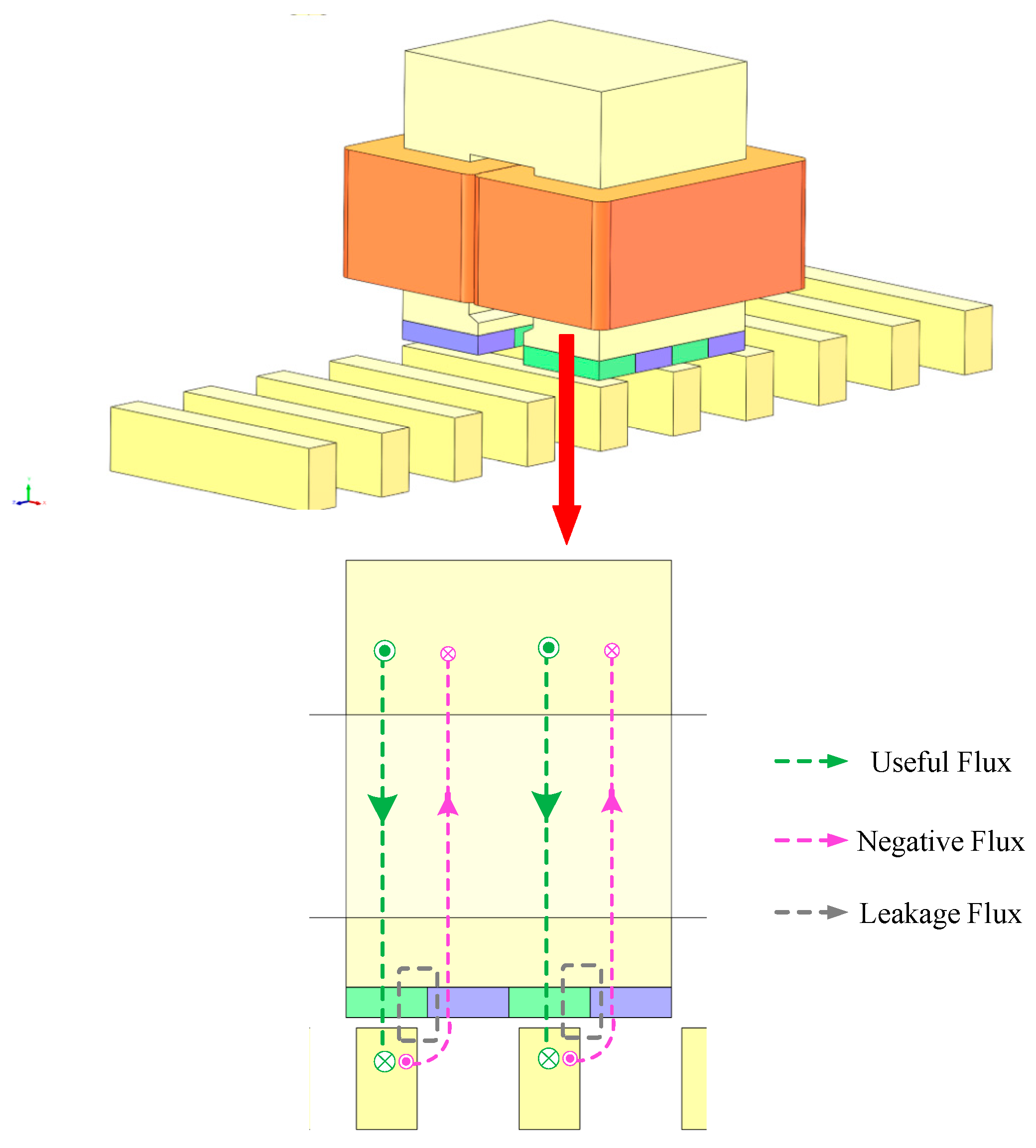
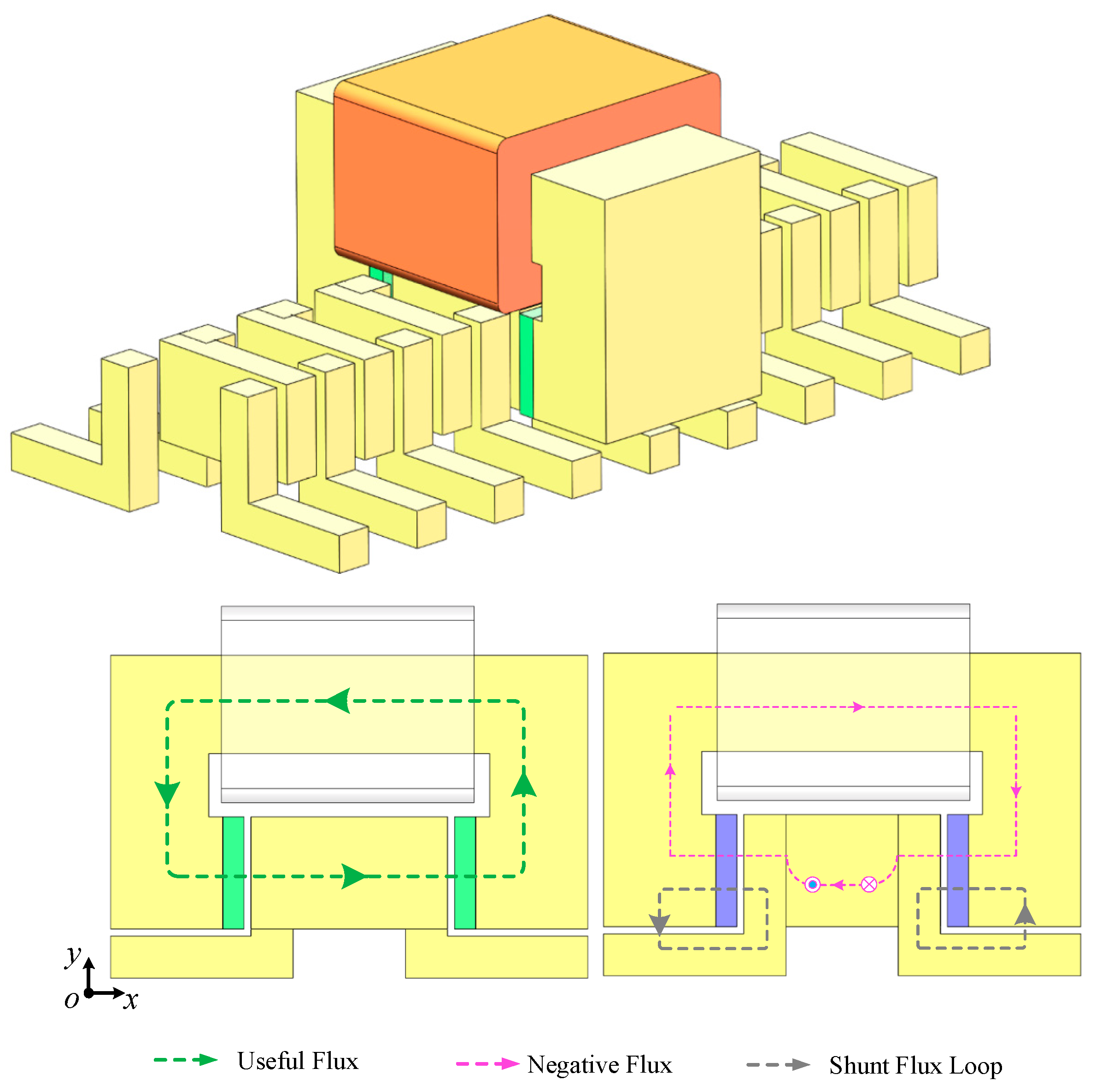
2.1. Improvement in the Motor Structure

As mentioned in the related literature, the serious flux leakage phenomenon in the transverse flux machines is a key factor that limits the further improvement in the thrust/torque density in this type of motor. The leakage flux could be separated into several components by distinguishing between different flux loops. In the existing TF-FRLM, the first leakage flux component is the negative flux excited by the ‘unused’ PMs, which is linked with the coil and closed up in the opposite direction of the positive flux loop, as the pink lines shown in Figure 1. The second component is the direct leakage flux between the adjacent PMs along the motion direction, which does not link with the coil, as the gray lines show in Figure 1.
From the view of qualitative analysis, to deal with either one or both two of the leakage components should significantly improve the total effective flux linked with the motor’s armature winding to generate effective motivation force.
To achieve that, a transformation and an update of the original structure of TF-FRLM is performed to achieve the target of increasing the total effective flux. The ‘transformation’ refers to the torsions of the primary cores, from the U-shaped cross-face to the C-shaped cross-face and from the motion direction view (z-axial view in this paper). This means the original planar gap is separated into two gaps; meanwhile, the total sum of the gaps’ surface area remains the same. The ‘update’ refers to the addition of some auxiliary secondary cores in the secondary, which is located at the blank space between the original I-shaped secondary cores. Benefiting from those two improvement measures by introducing the auxiliary cores, a new closed loop is proposed for the magnetic flux excited by the ‘unused’ PMs.
The transformed negative flux path can be described as shown in Figure 2: the flux excited by the “unused” negative PM firstly passes through one main gap into the auxiliary core, then it passes through the additional gap and directly returns to the source PMs. Thus, most of the negative PM flux directly flows within the “shunt loop” as the gray lines shown in the Figure 2, instead of linking with the armature winding. And the total effective PM flux linked with the armature winding is presented to grow larger, synchronous with the thrust/torque generated by the same driven current.

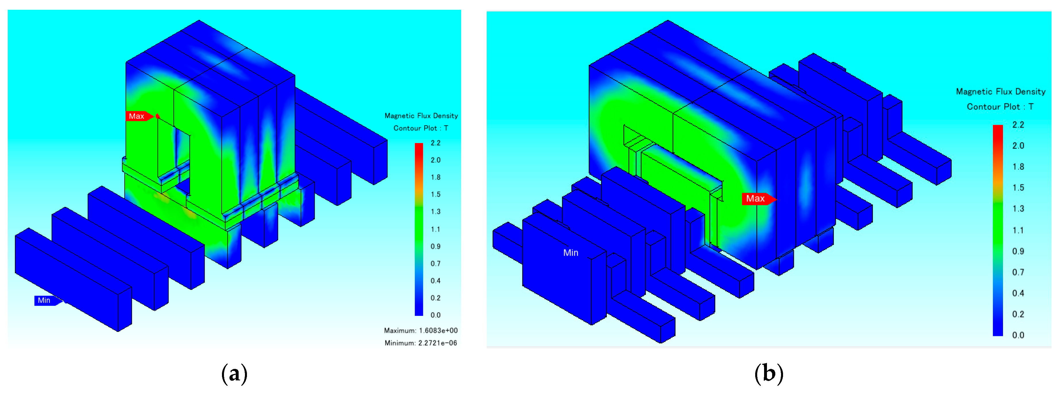
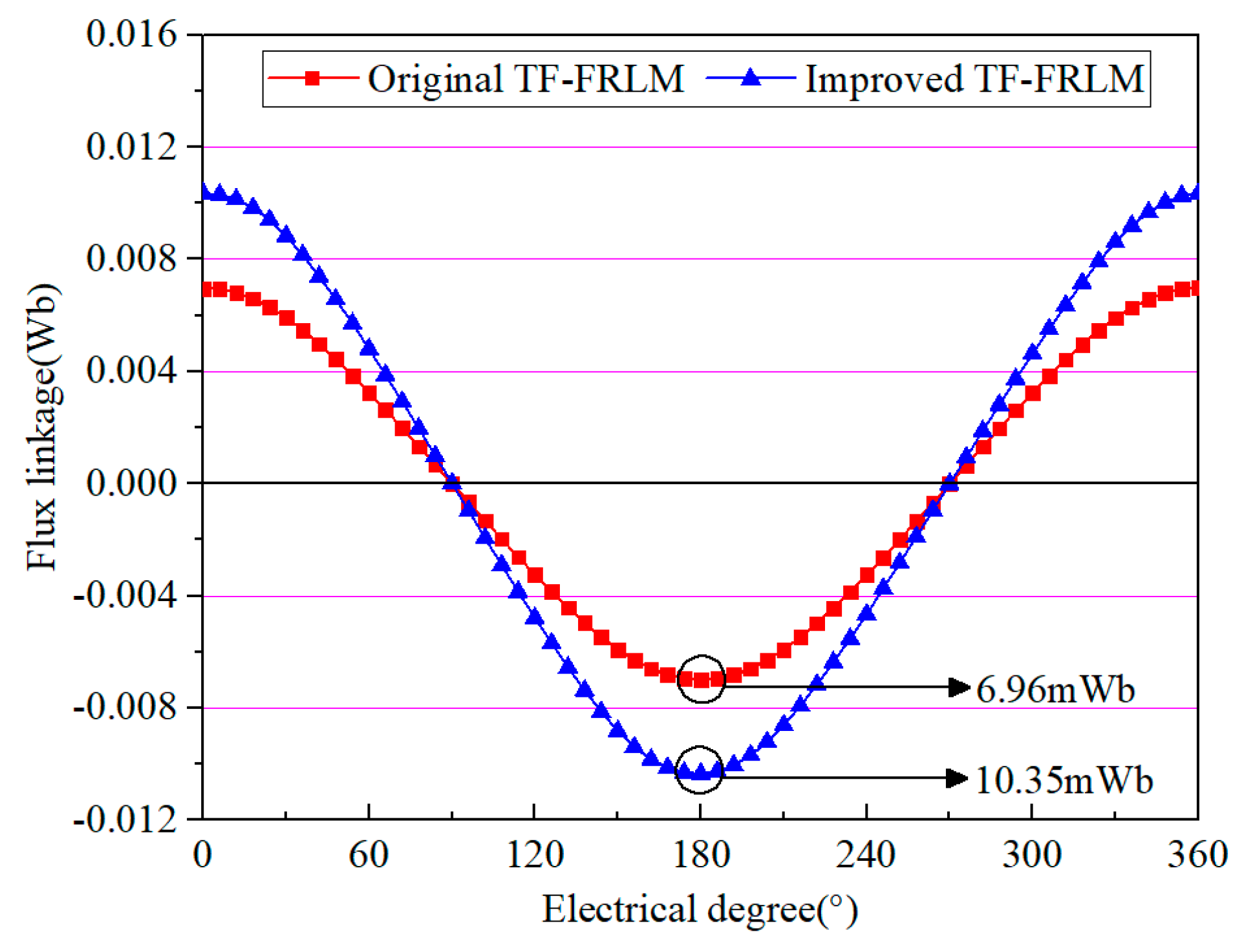
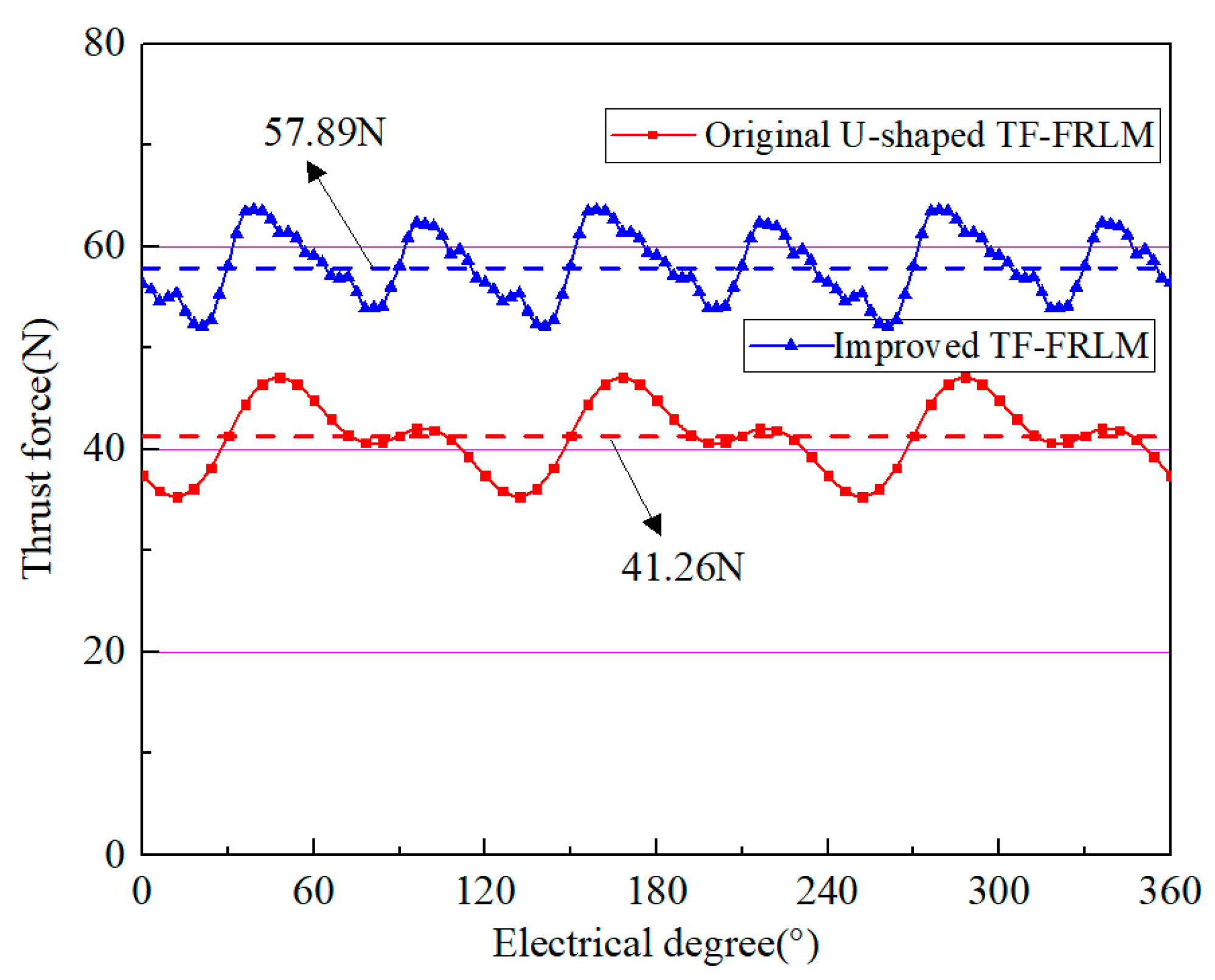
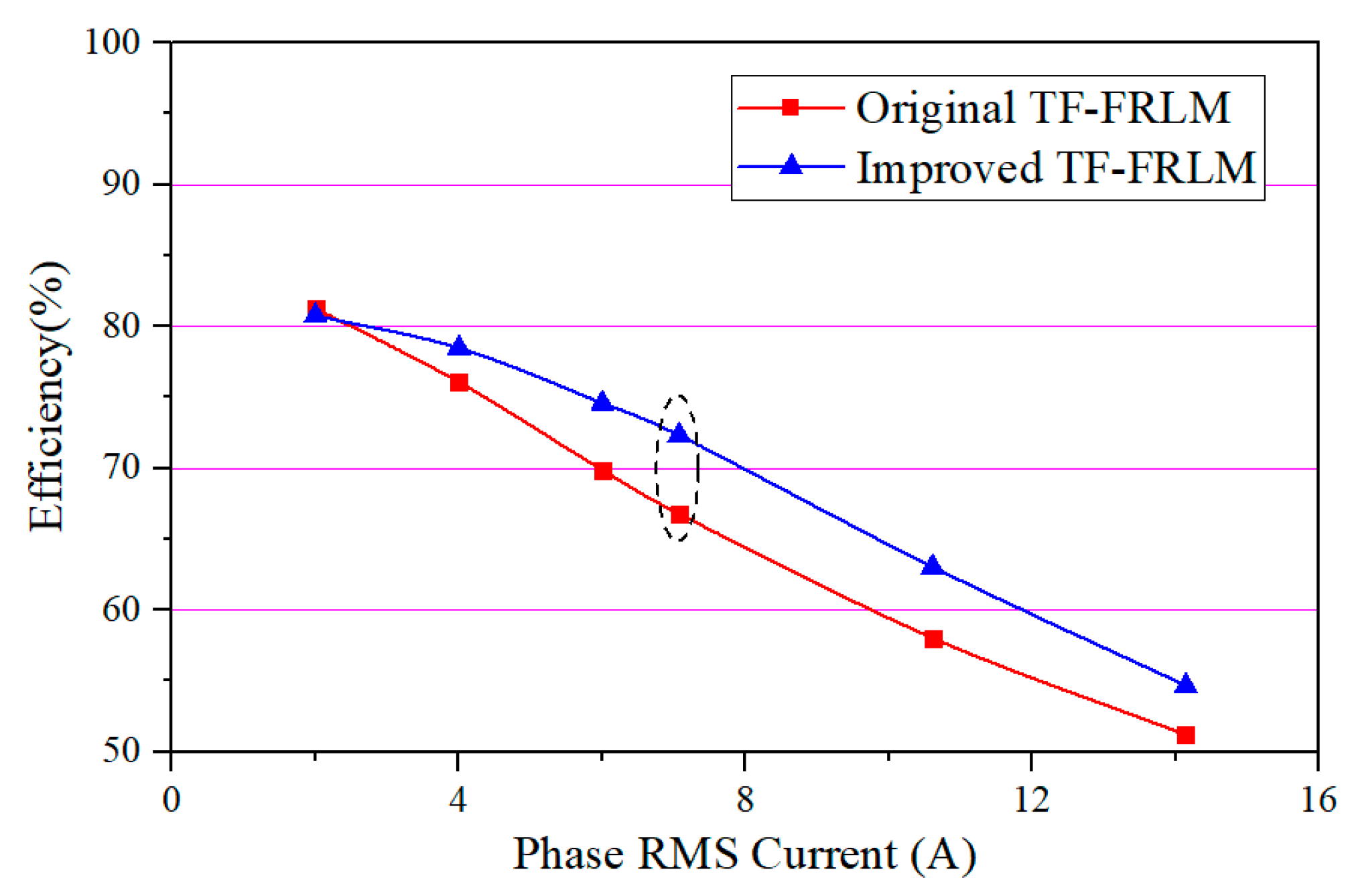
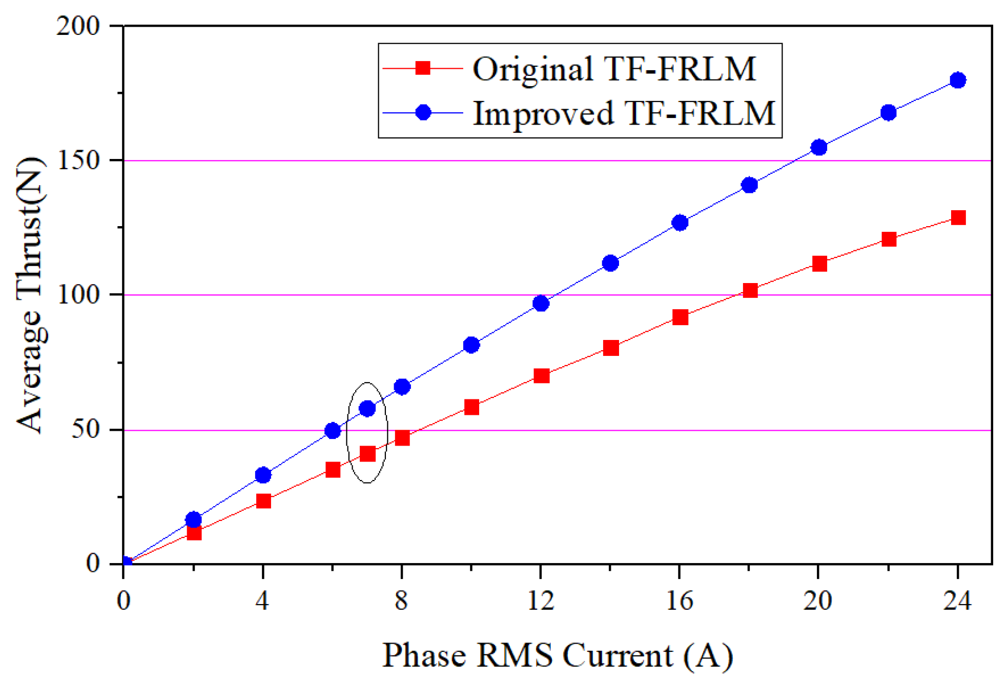
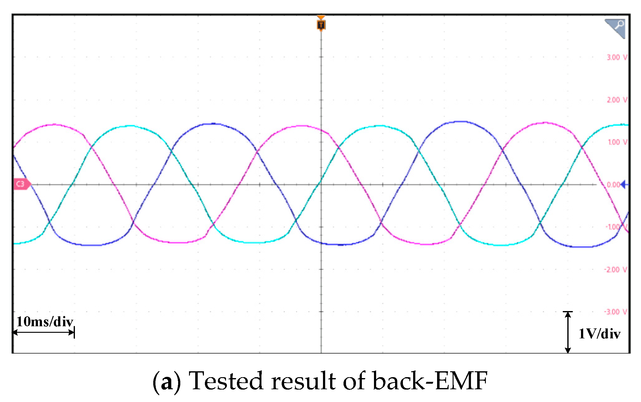
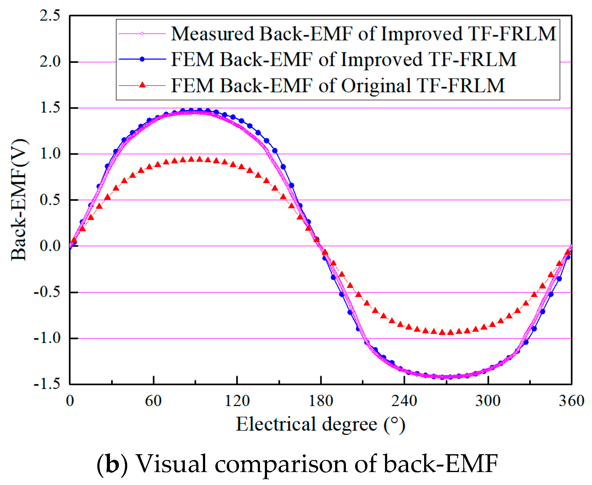
2.2. Verification of the Flux Linkage Enhancement Effect

In order to verify the flux linkage enhancement effect of the improved TF-FRLM compared with the original one, the quantitative analysis is investigated by the 3-D FEM model as shown in Figure 3. The detailed structural dimensions are listed in Table 1. The motor dimensions are designed to bring out relatively fair prerequisites for comparison, e.g., the same dimensions of PMs, the same winding turns, the same pole pitch, and the same driven current.
The results of PM flux linkage in the winding are shown in Figure 4, and the amplitude of the PM flux linkage in the original U-shaped TF-FRLM and the improved TF-FRLM is 6.96 mWb and 10.35 mWb, respectively. It is shown that the improvement in the PM flux linkage is nearly 48.7%. Since the total usage volume of PMs is equal in the two machines, the effect of the PM flux linkage improvement is significant.
When the ideal three-phase alternating sinusoidal currents are applied to the TF-FRLMs under the common Id = 0 control method, the results of the ideal thrust force are shown in Figure 5. The average value of the thrust force of the enhanced motor is 57.89 N, and the average thrust force of the original machine is 41.26 N. It can be seen that the improvement in the thrust force is 40.3% after the structure amelioration; the enhancement of the thrust force is also significant. This phenomenon is quite exciting and meaningful.
Meanwhile, the efficiency and overload capability are simulated and compared as shown in Figure 6 and Figure 7. Both the TF-FRLMs have good overload capacity; they can provide nearly 2.9 times the overload thrust under triple-excited current. Since the improved TF-FRLM has a larger thrust than the original one, the efficiency is synchronously higher under the same operation speed, and the efficiencies of both motors decrease when the phase current is increased.
For the further verification, the prototype of the enhanced TF-FRLM has been manufactured as shown in Figure 8. The primary is designed as a typical three-phase machine, which contains the C-shaped primary cores, the concentrated winding, and the PMs. The secondary of the prototype contains some alternating arranged I-shaped core and L-shaped auxiliary cores.
Based on the prototype, the back-EMF is measured and compared with finite element analysis results, as shown in Figure 9. From Figure 9, the symmetrical characteristic of the three-phased back-EMF are quite well for the manufactured linear machine. The amplitude of the back-EMF of the original motor is 0.92 Vand the amplitude of the back-EMF of the enhanced motor is 1.41 V, respectively. Since the tested motion speed is set to be 0.4 m/s, the measured results of back-EMF are consistent with the simulation results; there is only a 3.4% deviation. The improvement effect of the back-EMF can be verified. Since the thrust force is nearly proportional to the back-EMF when the input current is constant, the performance improvement by the importation of the novel shunt loop for the negative flux is verified.

3. MFPCC Control of TF-FRLM

In various industrial application scenarios, linear motors often undertake the function of transporting loads to complete unidirectional or bidirectional reciprocating linear motion. All actions are based on electromagnetic thrust, and the expected action effect can be achieved by controlling the magnitude and direction of the electromagnetic thrust. As the core component of the linear motor system, the driver and the control algorithm embedded inside the driver are the key to achieving various actions of the linear motor. Advanced control algorithms are a prerequisite for ensuring excellent control performance. Therefore, this section will focus on the limited stroke characteristics of the TF-FRLM prototype and study an MFPCC strategy suitable for this new type of linear motor. This method takes the natural response component of current variation as an adaptive variable and the measured current variation as a constraint term for each component, thereby achieving the goal of separating the current variation components.

3.1. Principle of the Proposed MFPCC

Under ideal conditions, the stator voltage equation of the TF-FRLM is similar to the one of the traditional PMLSM; when the motor is analyzed in the dq synchronous rotation reference frame, the stator voltage equation is given as follows:
d i d d t = R L d i d + u d L d + L q ω e i q L d d i q d t = R L q i q + u q L q ω e ( L d i d + ψ f ) L q
where u d , u q , i d , and i q are d-q axis stator voltages and currents. L and R are phase resistance and inductance. ψ f and ω e are the magnetic flux of the permanent magnet and the electrical angular velocity of the rotor.
Using the forward Euler method to process the TF-FRLM mathematical model, a discretization prediction model can be obtained as follows:
i d ( k + 1 ) = ( 1 T s R L d ) i d ( k ) + T s u d ( k ) L d + T s L q ω e i q ( k ) L d i q ( k + 1 ) = 1 T s R L q i q ( k ) + T s u q k L q T s L d ω e i d ( k ) L d T s ψ f ω e L q
where Ts is a control period. In a digital control system, the stator voltage and sampling current results will be maintained for one control period, and k and k + 1 in the equation correspond to the (k)th and (k + 1)th control period.
As is known, the three-phase two-level inverter can only output eight possible voltage vectors. Therefore, based on the discrete form of the ideal motor model, it is not difficult to predict the future behavior of TF-FRLM. Meanwhile, the optimal voltage vector that is most conducive to motor control performance can be obtained by minimizing the cost function, as follows:
J = i d * i d p r ( k + 2 ) + i q * i q p r ( k + 2 )
where i d p r , i q p r represents the predicted value; k + 2 corresponds to the (k + 2)th control period; and i d * , i q * are the reference currents of the dq-axis.
It is obviously that different current variation will be caused by voltage vector, and the current variations contain sufficient information about the actual behavior of the motor, which can be expressed as
i ( k ) = δ I ( k ) + δ i n ( k )
where k corresponds to the (k)th control period; δ I = [ δ I d , δ I q ] T represents the natural response of current variation; δ i n = [ δ I d n , δ I q n ] T can be seen as a forced response of current variations; and i ( k ) = i(k + 1) − i(k).
Under the assumption commonly used in MFPCC, the control period is short enough, and the current variations generated by the same vector in adjacent control periods are approximately equal. Thus, the following equations can be obtained
i p r ( k + 1 ) = i ( k ) + i _ ( k )
where i ( k ) is the sampling current; i _ ( k ) is the current variation corresponding to the voltage vector V _ ( k ) applied in the (k)th period.
According to the PMSM discrete model (2), it can be written in the following form:
δ I ( k ) = E ( k ) I ( k ) + F ( k ) δ i n ( k ) = L ( k ) U ( k )
where I = [id, iq]T and U = [ud, uq]T.
Based on the second equation in (6), the physical meaning of L(k) can be seen as the forced response of current variations to unit voltage, which is called the current variation per unit voltage (CVPUU) and redefined as δ i x _ :
δ i x _ ( k ) = δ i x u _ ( k ) u x _ ( k )
where δ i x _ ( k ) is called the current variations per unit voltage and u x _ ( k ) is the voltage vector applied to the inverter in the (k)th control period, which will cause a current forced response δ i x u _ ( k )   in the corresponding period.
Therefore, the equation in (3) can be transformed to
i x ( k + 1 ) i x ( k ) = δ I x ( k ) + δ i x _ ( k ) u x _ ( k )
Considering one-step delay, the current at the beginning of the (k + 1)th control period and the reference voltage vector predicts the following:
i x | p r ( k + 1 ) = i x ( k ) + δ I x ( k ) + δ i x _ ( k ) u x _ ( k )

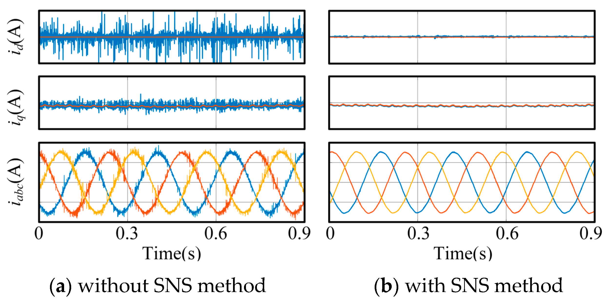
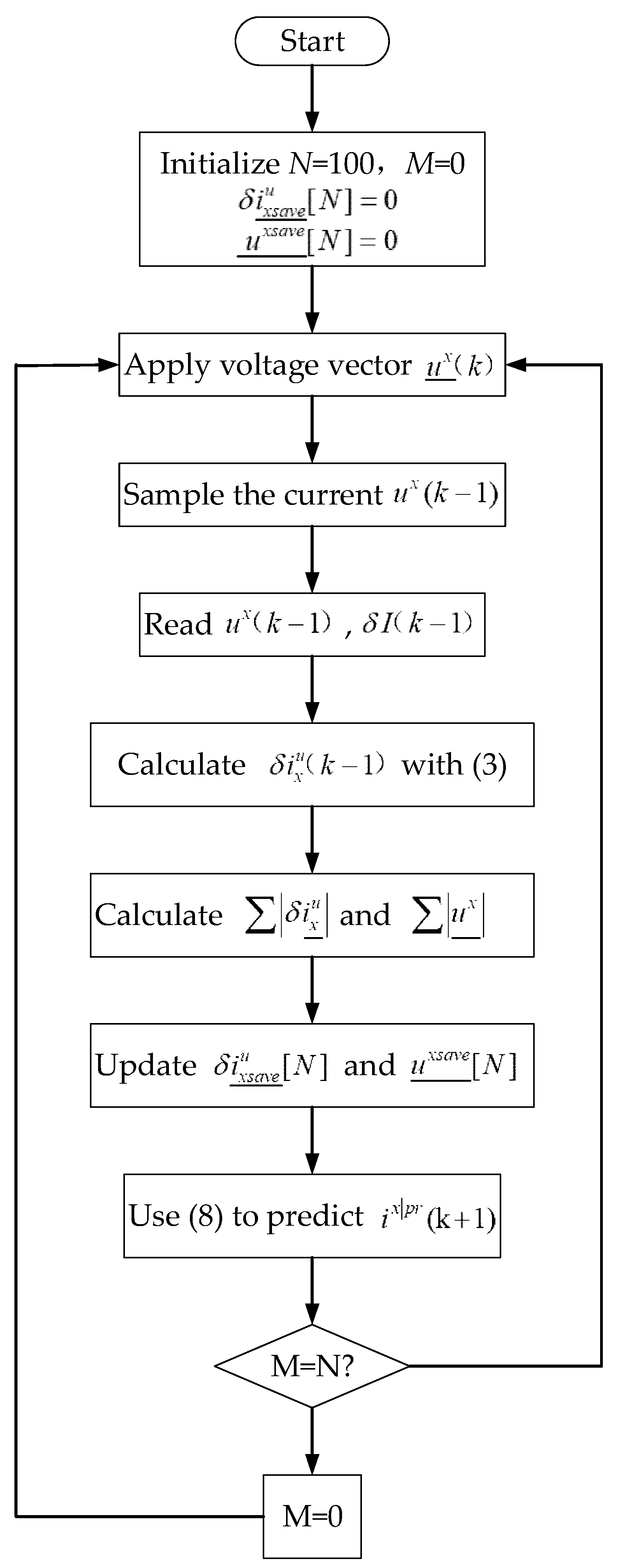
3.2. Sampling Noise Suppression

All model predictive current control strategies are implemented based on the sampling current in actual systems. However, in the actual current sampling process, sampling noise is inevitable. These sampling noises will be included in Equation (5), which further deteriorate the prediction of delay compensation current and reference voltage vector. In addition, the current estimation error caused by sampling noise will amplify the harmonic components of the motor’s phase current, resulting in increased control losses.
In order to suppress the influence of sampling noise on CVPUU, the principle of mean filtering is applied here. The essence of using the mean filtering method for denoising is to recover the true current to the maximum extent from the original sampled current data containing noise. Specifically, the following improvements have been made to CVPUU, as follows:
i x | p r ( k + 1 ) = i x ( k ) + δ I x ( k ) + δ i x _ ( k ) u x _ ( k )  
Based on the principle of mean filtering, the current variation per unit voltages are improved as follows:
δ i x _ ( k 1 ) = j = k N k 1 δ i x u _ ( j ) j = k N k 1 u x _ ( j )
where N represents the number of periods to sum.
Equation (10) can be rewritten as
δ i x _ ( k 1 ) = j = k N k 2 u x _ ( j ) j = k N k 1 u x _ ( j ) j = k N k 2 δ i x u _ ( j ) j = k N k 2 u x _ ( j ) + u x _ ( k 1 ) j = k N k 1 u x _ ( j ) δ i x u _ ( k 1 ) u x _ ( k 1 )
When the total number of cycles used for summation is large enough, the following equation holds:
δ i x _ ( k 2 ) j = k N k 2 δ i x u _ ( j ) j = k N k 2 u x _ ( j )
Substituting Equation (13) into Equation (12) and assuming η = u x _ ( k 1 ) j = k N k 1 u x _ ( j ) , then the second equation in (8) can be transformed to
δ i x _ ( k 1 ) = 1 η δ i x _ ( k 2 ) + η δ i x u _ ( k 1 ) u x _ ( k 1 )
It is obvious from Equation (14) that the transformed current variation per unit voltages is equivalent to the result of low-pass filtering on the original current variation per unit voltages, which can weaken the influence of sampling noise. The larger the value of N, the smaller the value of η , and the better the noise suppression performance. Meanwhile, the δ i x u _ and its corresponding voltage vector   u x _ in the adjacent N periods will be saved in arrays δ i x s a v e u _ [ N ] and   u x s a v e _ [N] for summation.
To comprehensively measure memory usage and noise suppression performance, this paper chooses N = 100.
In order to verify the effectiveness of the sampling noise suppression method, an ideal linear motor control model was established for comparison. Although the linear motor model is ideal in this simulation example, without considering the thrust fluctuations caused by friction, errors, and other factors in the actual system, there is a perfect linear relationship between the q-axis current and electromagnetic thrust. The artificial noise components were added to the sampling current, resulting in the variation in the motor dq axis current as shown in Figure 10.
From Figure 10, when the sampling noise suppression module is not added, significant high-order harmonic components are present in the phase current and dq current of the linear motor due to the influence of sampling current noise; after adding the proposed sampling noise suppression module based on the mean filtering principle, the current waveform of the motor was significantly improved, and the current waveform became more ideal, proving the effectiveness of the proposed method under the ideal model.
The control flowchart of the proposed MFPCC in the digital system implementation is shown in Figure 11, which can be mainly divided into four stages. The first stage is the preparation phase, which includes initializing variables, sampling stator currents, and reading voltages u _ x ( k 1 ) and u _ x ( k ) in chronological order. Then, the natural response component and forced response component of the current variation are calculated based on the proposed adaptive strategy. Moving on to the third stage, CVPUUs with sampling noise suppression are calculated. Finally, according to the principle of MFPCC, the reference voltage vector for the next control period is predicted.
The diagram of the control system based on these steps is shown in Figure 12. The total control diagram contains three closed loops: the inner current loop is controlled based on the MFPCC; both the speed loop and the position loop are controlled based on the traditional PI controller. As mentioned in the literature, the PI controller is a common feedback controller that regulates the system through proportional (P) and integral (I) control actions, which has the advantages of a simple structure and well control effect [24,25].
U ( t ) = K P e ( t ) + K P 0 t e ( t ) d t
Based on the simplified transfer function of the system and the zero-pole cancellation configuration method, the proportional and integral coefficients can be calculated. Based on the parameter tuning strategy in [26] and small scale debugging on the experimental platform system mentioned in this paper, the proportional coefficient of the speed loop is set to 0.005, and the integral coefficient of the speed loop is set to 1; the proportional coefficient of the position loop is 10, and the integral coefficient is 25.

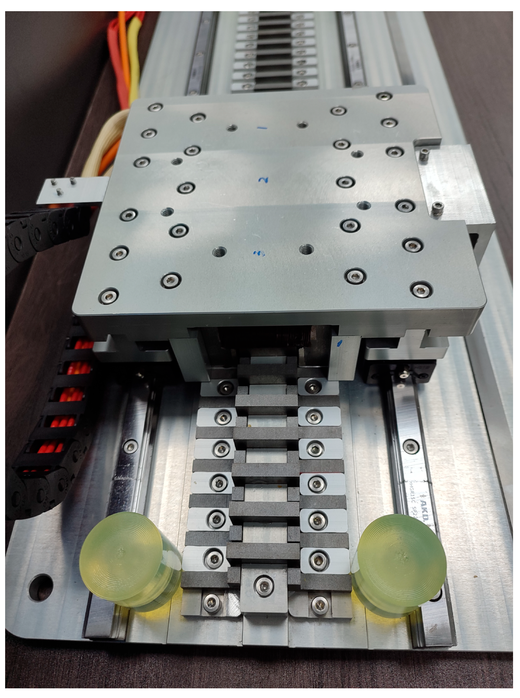
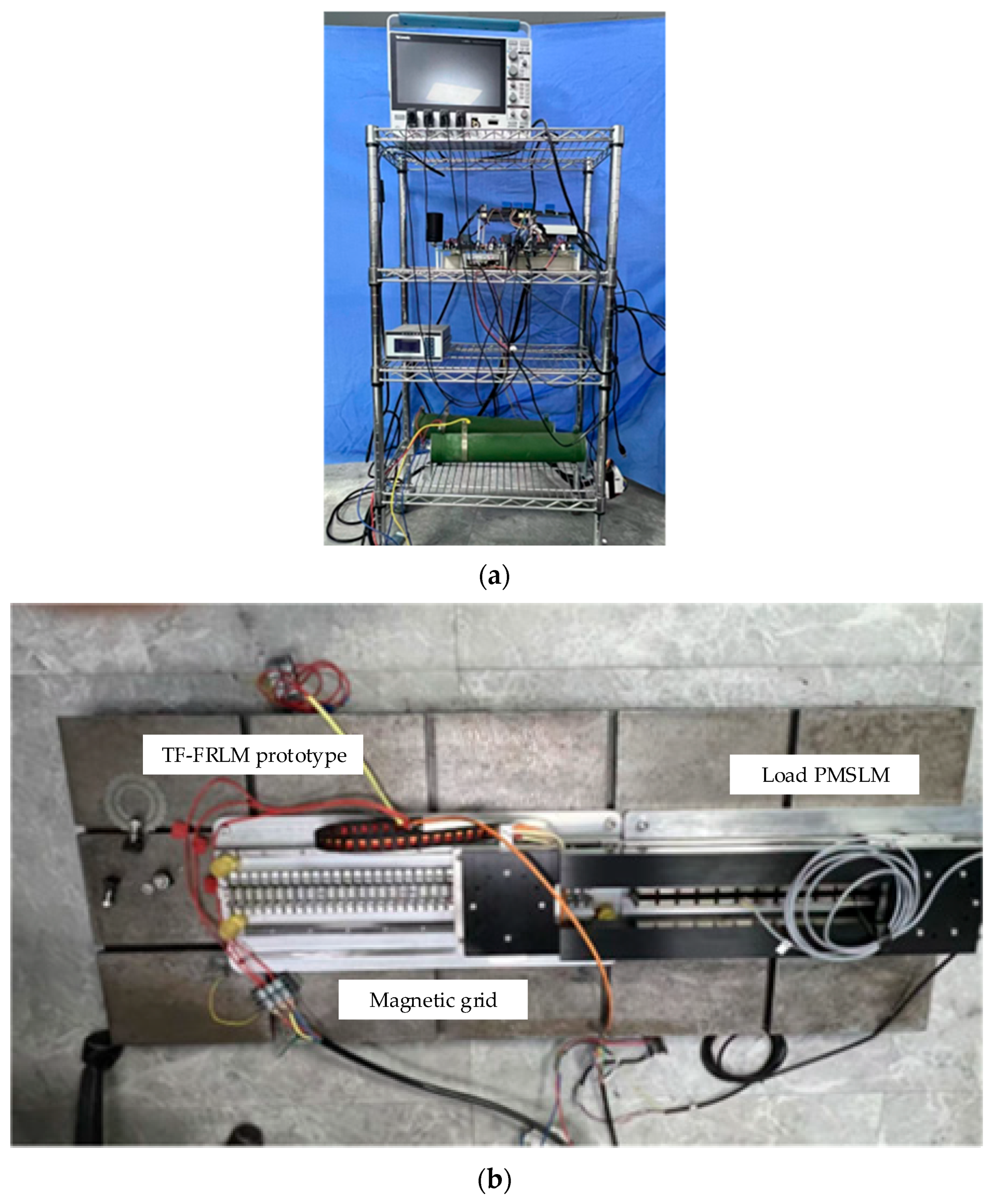
4. Experimental Verification

In order to verify the effectiveness of the proposed MFPCC method for the proposed TF-FRLM, experimental verification was conducted. For the experimental verification, the prototype of TF-FRLM has been manufactured. The dimensions of the prototype are the same as those in Table 1. In order to obtain the characteristics of the proposed method more intuitively, comparative experiments were conducted with traditional MFPCC and the proposed MFPCC strategies. All algorithms were completed on the experimental platform shown in Figure 13.

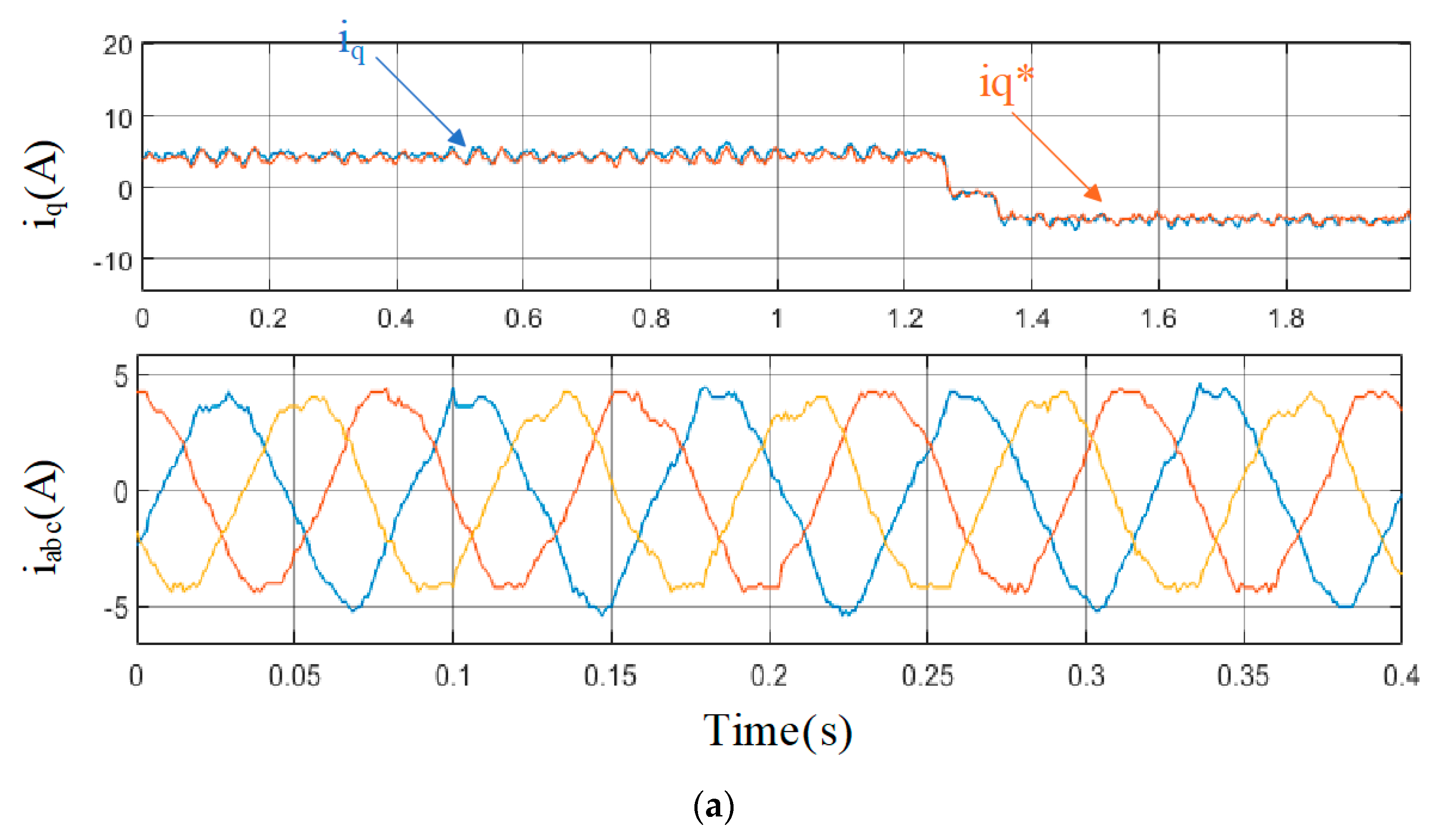
4.1. Steady State Performance

Figure 14 shows the experimental results of conventional MFPCC and proposed MFPCC under no loads. From Figure 14a,b, it can be obviously seen that when the proposed TF-FRLM has no load, there is a significant tracking error in the d-axis current when using traditional MFPCC, while the proposed MFPCC has much less. For the q-axis current, both methods take significant oscillation, especially while reversing the direction of the proposed TF-FRLM. Compared with traditional MFPCC, it can be seen that the proposed MFPCC has a better performance with regard to the q-axis current; thus, the proposed MFPCC method can achieve suppressing sampling noise.
Meanwhile, for the three-phase current iabc, it can be seen that it obviously takes significant oscillation in the method of traditional MFPCC, while proposed MFPCC makes iabc smooth. Thus, the proposed MFPCC has better steady state performance in the proposed TF-FRLM.
Figure 15 shows the comparative experimental results for the proposed MFPCC strategy with parameter mismatch, e.g., with 50%ψf, with 150%ψf, with 50% Ls, and with 150% Ls. It can be obviously seen that even in the case of non-nominal parameters, the proposed MFPCC still has a good current tracking performance as shown in Figure 15a–d. The above steady-state experimental results demonstrate that compared to existing technologies, the proposed MFPCC achieves better control performance without affecting robustness. Compared to traditional MFPCC, the proposed MFPCC has extremely strong robustness.
Meanwhile, the tested currents own significant harmonic components, this is caused by the actual motor system, mainly due to the non-idealization of motor thrust. According to the motion equilibrium equation of linear motor system, the electromagnetic thrust can be divided as
F e ( k 2 ) = F L ( k 2 ) + M d v ( t ) d t + B v ( k 2 )
where F e is the instantaneous electromagnetic thrust, F L is the load force, M is the mass weight of moving parts, v is the motion speed, and B is the equivalent coefficient of friction.
In the ideal simulation analysis, the fluctuation component of electromagnetic thrust and the fluctuation component of load force are usually ignored. Thus, in the steady-state motor model, the q-axis current only contains a DC component, and the currents of each phase are approximately ideal sinusoidal. However, as shown in Figure 5, the manufactured prototype is subject to significant thrust ripple due to the influence of detent force even when supplied with ideal sinusoidal current. In actual experimental systems, there are more fluctuations caused by friction and mechanical disturbances. In addition to dealing with the DC component of the average thrust, there are also high-order harmonic components related to thrust ripple in the q-axis reference current calculated by the control system to balance with the actual total load force. This perturbed reference current will cause significant harmonic components in the three-phase current after coordinate transformation, which is determined by the performance of the motor. How to further suppress it through TF-FRLM optimization and control compensation strategies based on current research platform in this paper is the focus of future work. Of course, the existing tested results have demonstrated that the proposed current inner loop control strategy can effectively track reference instructions in various parameter mismatches, thus proving the effectiveness of the aforementioned control strategy principle.

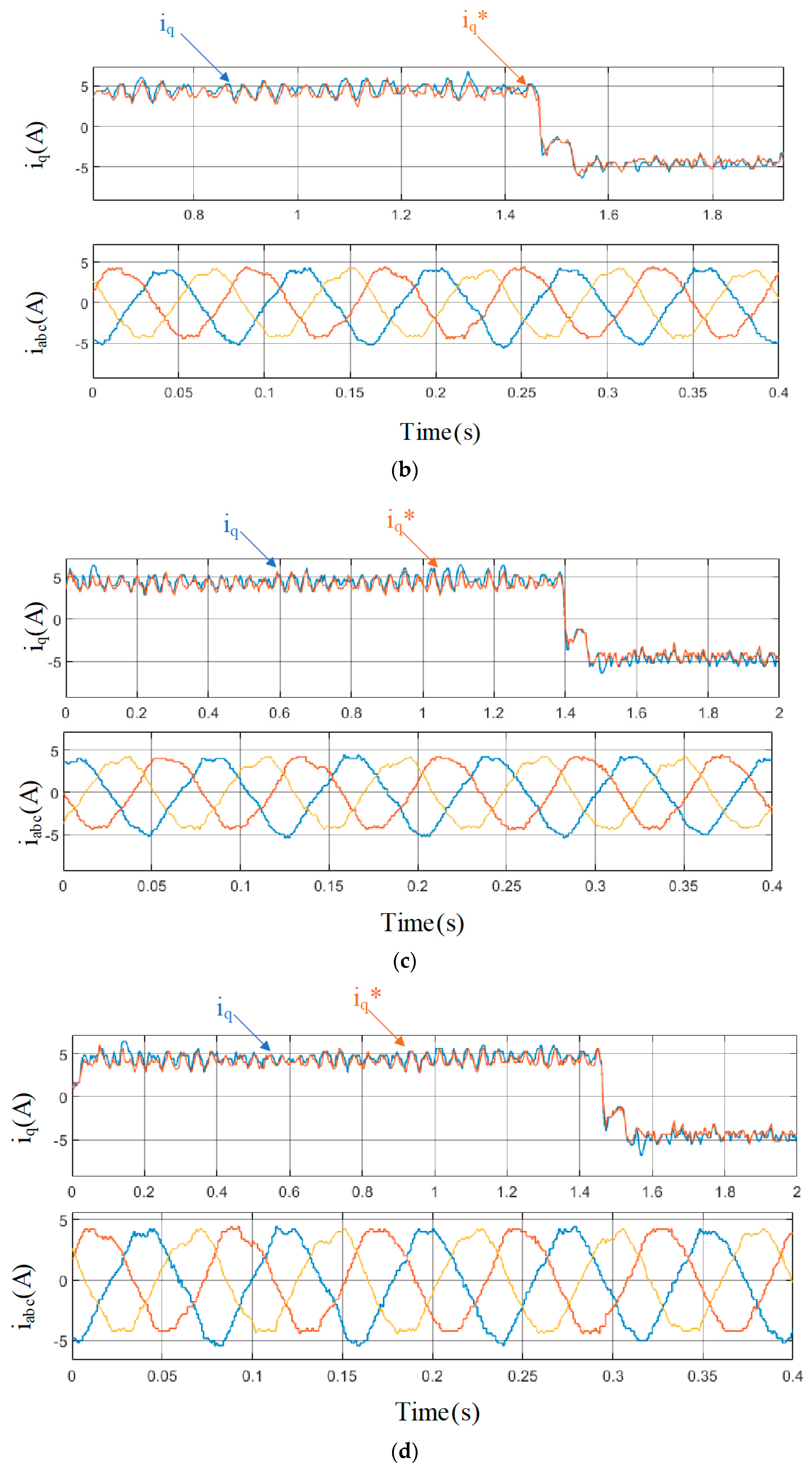
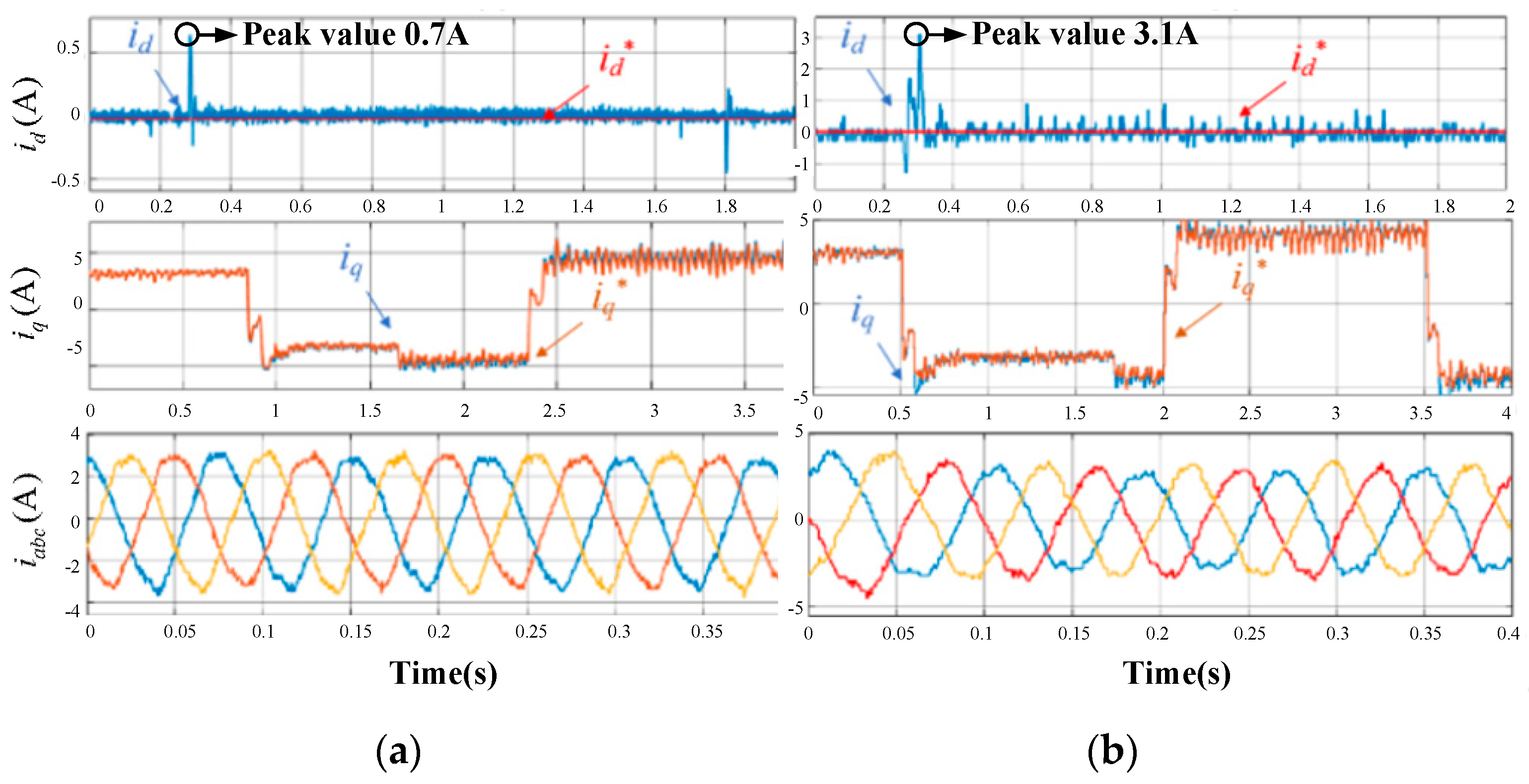
4.2. Dynamic Performance

In order to verify the dynamic performance of the proposed strategy in the proposed TF-FRLM, testing experiments were conducted.
Figure 16 shows the response characteristics of the traditional MFPCC method and the proposed MFPCC method when the load steps from none to 20 N.
Compared between the traditional MFPCC method and the proposed MFPCC method, it can be seen that after the load stepping, there is a significant oscillation in the d-axis current; meanwhile, the tracking error in the d-axis current when using the traditional MFPCC is larger. The peak d-axis current under the traditional MFPCC method reached nearly 3.1 A, which makes sampling noise much larger. For the q-axis current, a significant oscillation can be seen in Figure 16, especially while reversing the direction. However, the significant oscillation in the traditional MFPCC method is much larger than the significant oscillation in the proposed MFPCC method, which means faster tracking and higher efficiency under the proposed control method. For the three-phase current iabc, there is a larger significant oscillation in the method of the proposed MFPCC, while it is still better than the method of the traditional MFPCC, with a smoother waveform. Based on the above dynamic-state experimental results, compared to existing MFPCC technologies, the proposed MFPCC achieves a better current performance, thus achieving the suppression of sampling noise.

5. Conclusions

An improved MFPCC strategy has been proposed for the improved TF-FRLM, considering suppressing sampling noise in this paper. This strategy only utilizes the adaptive natural response component and CVPUU to predict future reference voltage vectors and does not require any machine parameters. Meanwhile, it does not require any observers, thus possessing excellent robustness. With the experimental results on the platform of the improved TF-FRLM, it has been shown that compared to traditional MFPCC methods, the proposed MFPCC has a stronger parameter robustness and a better steady-state performance. Furthermore, because of the much smaller significant oscillation in current, it can be proved that the proposed MFPCC can achieve the suppression of sampling noise in the traditional MFPCC. In addition, through comparative experiments on MFPCC schemes, it is demonstrated that the proposed MFPCC has improved both steady-state and dynamic performance in the proposed TF-FRLM.

Author Contributions

Investigation, data analysis, establishment of model, simulation and preliminary analysis, writing—original draft preparation, Q.L.; simulation and preliminary analysis, parameter analysis, writing—original draft preparation, X.H.; writing—review and editing, X.Y. All authors have read and agreed to the published version of the manuscript.

Funding

This research was funded by project ZR2022QE279, supported by Shandong Provincial Natural Science Foundation; Science and Technology Project of State Grid Gansu Electric Power Co., Ltd. (52272223004D); National Natural Science Foundation of Sichuan under Grant 2023NSFSC0826.

Data Availability Statement

The original contributions presented in this study are included in the article. Further inquiries can be directed to the corresponding author.

Conflicts of Interest

Authors Xin He and Quanmao Li were employed by the company Electric Power Research Institute, State Grid Gansu Electric Power Company, Lanzhou, China. This work was funded by the Science and Technology Project of State Grid Gansu Electric Power Co., Ltd. The remaining author declares no conflicts of interest.

References

  1. Zhang, Z.; Luo, M.; Duan, J.-A.; Kou, B. Design and Analysis of a Novel Frequency Modulation Secondary for High-Speed Permanent Magnet Linear Synchronous Motor. IEEE/ASME Trans. Mechatron. 2022, 27, 790–799. [Google Scholar] [CrossRef]
  2. Zhao, J.; Mou, Q.; Zhu, C.; Chen, Z.; Li, J. Study on a Double-Sided Permanent-Magnet Linear Synchronous Motor with Reversed Slots. IEEE/ASME Trans. Mechatron. 2021, 26, 3–12. [Google Scholar] [CrossRef]
  3. Jiao, Z.; Wang, T.; Yan, L. Design of a Tubular Linear Oscillating Motor with a Novel Compound Halbach Magnet Array. IEEE/ASME Trans. Mechatron. 2017, 22, 498–508. [Google Scholar] [CrossRef]
  4. Lv, G.; Liu, Y.; Zhang, Z.; Zhou, T. Characteristic Analysis of Coreless-Type Linear Synchronous Motor with the Racetrack Coils as Secondary for EDS Maglev Train. IEEE/ASME Trans. Mechatron. 2022, 27, 4654–4664. [Google Scholar] [CrossRef]
  5. Luo, J.; Kou, B.; Yang, X.; Zhang, H.; Zhang, L. Development, Design, and Analysis of a Dual-Consequent-Pole Transverse Flux Linear Machine for Direct-Drive Applications. IEEE Trans. Ind. Electron. 2021, 68, 6097–6108. [Google Scholar] [CrossRef]
  6. Li, X.; Xu, W.; Ye, C.; Boldea, I. Comparative Study of Transversal-Flux Permanent-Magnetic Linear Oscillatory Machines for Compressor. IEEE Trans. Ind. Electron. 2018, 65, 7437–7446. [Google Scholar] [CrossRef]
  7. Xu, W.; Li, X.; Zhu, J.; Wang, Q. 3-D Modeling and Testing of a Stator-Magnet Transverse-Flux Linear Oscillatory Machine for Direct Compressor Drive. IEEE Trans. Ind. Electron. 2021, 68, 8474–8486. [Google Scholar] [CrossRef]
  8. Shin, J.-S.; Watanabe, R.; Koseki, T.; Kim, H.-J. Practical Design Approach of a Transverse Flux Linear Synchronous Motor for Compact Size, Small Mover Weight, High Efficiency, and Low Material Cost. IEEE Trans. Magn. 2015, 51, 8200504. [Google Scholar] [CrossRef]
  9. Yang, X.; Zhou, Y. PM Flux Analysis and Thrust Density Enhancement of a Transverse-flux Flux-reversal Linear Motor for Transportation System. IEEE Trans. Transp. Electrif. 2024, 10, 5294–5306. [Google Scholar] [CrossRef]
  10. Chen, M.; Huang, L.; Li, Y.; Meng, G.; Xia, T. A Low Thrust Ripple Flux-Reversal Transverse Flux Permanent Magnet Linear Generator Used in Direct Drive Wave Energy Converter. IEEE Trans. Magn. 2024, 60, 8600505. [Google Scholar] [CrossRef]
  11. Sui, Y.; Yin, Z.; Wang, M.; Yu, B.; Zheng, P. A Tubular Staggered-Teeth Transverse-Flux PMLM with Circumferentially Distributed Three-Phase Windings. IEEE Trans. Ind. Electron. 2019, 66, 4837–4848. [Google Scholar] [CrossRef]
  12. Chen, H.; Nie, R.; Zhao, W.; Liu, J. A Novel Three-Phase Tubular Switched Reluctance Linear Machine with Transverse-Flux Path. IEEE Trans. Appl. Supercond. 2020, 30, 5204606. [Google Scholar] [CrossRef]
  13. Chen, M.; Huang, L.; Tan, P.; Li, Y.; Ahmad, G.; Hu, M. A Stator-PM Transverse Flux Permanent Magnet Linear Generator for Direct Drive Wave Energy Converter. IEEE Access 2021, 9, 9949–9957. [Google Scholar] [CrossRef]
  14. Vazquez, S.; Leon, J.I.; Franquelo, L.G.; Rodriguez, J.; Young, H.A.; Marquez, A.; Zanchetta, P. Model predictive control: A review of its applications in power electronics. IEEE Ind. Electron. Mag. 2014, 8, 16–31. [Google Scholar] [CrossRef]
  15. Elmorshedy, M.F.; Xu, W.; Allam, S.M.; Rodriguez, J.; Garcia, C. MTPA-based finite-set model predictive control without weighting fac- tors for linear induction machine. IEEE Trans. Ind. Electron. 2021, 68, 2034–2047. [Google Scholar] [CrossRef]
  16. Wang, F.; Li, S.; Mei, X.; Xie, W.; Rodriguez, J.; Kennel, R.M. Model-based predictive direct control strategies for electrical drives: An experimental evaluation of PTC and PCC methods. IEEE Trans. Ind. Inform. 2015, 11, 671–681. [Google Scholar] [CrossRef]
  17. Zhang, X.; Hou, B.; Mei, Y. Deadbeat Predictive Current Control of Permanent-Magnet Synchronous Motors with Stator Current and Disturbance Observer. IEEE Trans. Power Electron. 2017, 32, 3818–3834. [Google Scholar] [CrossRef]
  18. Wang, L.; Zhao, J.; Yang, X.; Zheng, Z.; Zhang, X.; Wang, L. Robust Deadbeat Predictive Current Regulation for Permanent Magnet Synchronous Linear Motor Drivers with Parallel Parameter Disturbance and Load Observer. IEEE Trans. Power Electron. 2022, 37, 7834–7845. [Google Scholar] [CrossRef]
  19. Zhou, Y.; Li, H.; Yao, H. Model-free control of surface mounted PMSM drive system. In Proceedings of the 2016 IEEE International Conference on Industrial Technology (ICIT), Taipei, Taiwan, 14–17 March 2016; pp. 175–180. [Google Scholar]
  20. Lin, C.-K.; Liu, T.-H.; Yu, J.-T.; Fu, L.-C.; Hsiao, C.-F. Model-Free Predictive Current Control for Interior Permanent-Magnet Synchronous Motor Drives Based on Current Difference Detection Technique. IEEE Trans. Ind. Electron. 2014, 61, 667–681. [Google Scholar] [CrossRef]
  21. Carlet, P.G.; Tinazzi, F.; Bolognani, S.; Zigliotto, M. An Effective Model-Free Predictive Current Control for Synchronous Reluctance Motor Drives. IEEE Trans. Ind. Appl. 2019, 55, 3781–3790. [Google Scholar] [CrossRef]
  22. Hu, C.; Yin, Z.; Rui, T.; Zhang, Z.; Shen, W.; Cao, W.; Holmes, D.G. A Novel Double-Voltage-Vector Model-Free Predictive Current Control Method for Two-Level Voltage Source Inverters. IEEE Trans. Ind. Electron. 2023, 70, 5872–5884. [Google Scholar] [CrossRef]
  23. Zhou, Y.; Li, H.; Liu, R.; Mao, J. Continuous Voltage Vector Model-Free Predictive Current Control of Surface Mounted Permanent Magnet Synchronous Motor. IEEE Trans. Energy Convers. 2019, 34, 899–908. [Google Scholar] [CrossRef]
  24. Song, W.; Li, J.; Ma, C.; Xia, Y.; Yu, B. A Simple Tuning Method of PI Regulators in FOC for PMSM Drives Based on Deadbeat Predictive Conception. IEEE Trans. Transp. Electrif. 2024, 10, 9852–9863. [Google Scholar] [CrossRef]
  25. Mao, M.; Zhang, Z.; Ding, Y.; Shi, H.; Chang, L. PI parameters design of universal controller for PMSG-WGS based on per-unit system. In Proceedings of the 2015 IEEE Energy Conversion Congress and Exposition (ECCE), Montreal, QC, Canada, 20–24 September 2015; pp. 1681–1688. [Google Scholar]
  26. Lidozzi, A.; Solero, L.; Crescimbini, F.; Di Napoli, A. Direct tuning strategy for speed controlled PMSM drives. In Proceedings of the 2010 IEEE International Symposium on Industrial Electronics, Bari, Italy, 4–7 July 2010; pp. 1265–1270. [Google Scholar] [CrossRef]
Figure 1. Structure of TF-FRLM and the simplified flux distribution components within the motor.
Electronics 14 02477 g001
Figure 2. Structure of the improved TF-FRLM and the simplified flux distribution components within the motor.
Electronics 14 02477 g002
Figure 3. Three-dimensional FEM contour plot of the magnetic flux density of the TF-FRLMs. (a) Original one. (b) Improved one.
Electronics 14 02477 g003
Figure 4. Flux linkage waveforms of the TF-FRLMs.
Electronics 14 02477 g004
Figure 5. Electromagnetic thrust force waveforms of the TF-FRLMs.
Electronics 14 02477 g005
Figure 6. Efficiency of TF-FRLMs under 0.8 m/s.
Electronics 14 02477 g006
Figure 7. Overload capability of the TF-FRLMs.
Electronics 14 02477 g007
Figure 8. The prototype of the improved TF-FRLM.
Electronics 14 02477 g008
Figure 9. The back-EMF waveforms of the prototype of TF-FRLM.
Electronics 14 02477 g009aElectronics 14 02477 g009b
Figure 10. The effect of the sampling noise suppression method in the TF-FRLM system.
Electronics 14 02477 g010
Figure 11. Control flowchart of the proposed MFPCC.
Electronics 14 02477 g011
Figure 12. Block diagram of the MFPCC control for the improved TF-FRLM.
Electronics 14 02477 g012
Figure 13. Experimental platform of TF-FRLM. (a) Hardware system; (b) Drag platform.
Electronics 14 02477 g013
Figure 14. Experimental results of TF-FRLM with no load. (a) Proposed MFPCC. (b) Traditional MFPCC.
Electronics 14 02477 g014
Figure 15. Experimental results of MFPCC with parameter mismatch under 20 N load. (a) MFPCC with 50%ψf. (b) MFPCC with 150%ψf. (c) MFPCC with 50% Ls. (d) MFPCC with 150% Ls.
Electronics 14 02477 g015aElectronics 14 02477 g015b
Figure 16. Experimental results of TF-FRLM with no load at first, then a sudden load. (a) Proposed MFPCC. (b) Traditional MFPCC.
Electronics 14 02477 g016
Table 1. Dimension parameters of the investigated TF-FRLM.
ParameterU-Shaped TF-FRLM as Figure 1Improved C-shaped TF-FRLM as Figure 2
Geometric dimensionspole pitch8 mm8 mm
pole pairs22
tooth width14 mm14 mm
slot width14 mm7 mm
slot height20 mm40 mm
magnet length16 mm16 mm
magnet width8 mm8 mm
magnet height3 mm3 mm
gap length1 mm1 mm
Electrical parameterswinding turns100100
rated current7 A7 A
phase number33
Disclaimer/Publisher’s Note: The statements, opinions and data contained in all publications are solely those of the individual author(s) and contributor(s) and not of MDPI and/or the editor(s). MDPI and/or the editor(s) disclaim responsibility for any injury to people or property resulting from any ideas, methods, instructions or products referred to in the content.

