Abstract
Traditional multi-class classification circuits mostly use the mechanism of winner-take-all. In this paper, a memristor-based classification circuit with the loser-take-all mechanism is designed. The winner-take-all mechanism selects the most active neuron or signal while suppressing others, whereas the loser-take-all mechanism suppresses the most active and amplifies weaker signals. The goal of the loser-take-all mechanism is to determine which class an item does not belong to, rather than to determine which class the item belongs to. The loser-take-all mechanism can use relatively undemanding criteria to correctly classify the majority of categories that are misclassified by the winner-take-all mechanism. The designed circuit includes input modules, control modules and suppression modules which realize the multi-classification function based on the loser-take-all mechanism. The simulation results in Cadence show that the circuit can be used to realize complicated classification applications. The memristor-based classification circuit with the loser-take-all mechanism can capture the subtle nuances of various categories and provide a flexible approach to classification tasks.
1. Introduction
Multi-class classification is a research hotspot in classification circuits. In traditional multi-class classification [1,2], the goal is to find an optimal decision boundary that maximizes the correct classification of classes. Loser-take-all is a mechanism used in various computational models and neural networks to identify the minor element among a group of competing elements [3]. The loser-take-all mechanism has broad applications, including image recognition [4], decision-making systems [5], and associative memory models [6,7,8,9,10,11,12]. In current research, few researchers utilize analog circuits for multi-class classification due to the limitations of circuit devices. Nonvolatile resistive memory devices have been invented based on biomaterial or conventional oxides; they provide a new approach for circuit design [13]. As a passive two-terminal device, memristor plays an essential role in analog circuits by advantages of its nanoscale size, non-linearity, memory function and other characteristics [14,15,16,17,18,19]. Benefiting from the dynamic characteristics of memristor, the simple hyperchaotic memristor circuit with attractor evolution and large-scale parameter permission was designed in [20]. The dynamic characteristics of memristors are highly similar to those of neural synapses, which provides conditions for realizing neuromorphic computing by building analog circuits [21,22,23,24,25]. With memristor as the core device, memristive neural network circuits have been implemented in various applications, such as operant conditioning and image recognition [26,27].
A number of studies of multi-class classification based on memristive circuits have been implemented so far. A memristor-based cascaded framework was proposed to improve specific target recognition in [28]. A circuit-based hybrid quantum convolutional neural network was proposed as an image classifier in [29]. In [30], an automatic sorting system was proposed to classify electronic components from waste printed circuit boards. In [31], an analog circuit was designed to remove noise in images and a digital image filtering method called median filtering was proposed. A complete design of a memristive network circuit was proposed in [32]. It can solve hardware acceleration of long short-term memory and improve the accuracy of network classification. However, most studies do not consider the loser-take-all mechanism in multi-class classification circuits.
The loser-take-all mechanism is a decision-making process where only one part emerges as the loser. For the loser-take-all mechanism, the neuron with the weakest activation becomes active while the stronger ones are suppressed. The mechanism plays a significant role in determining outcomes. In the manufacturing industry, a classification circuit with the loser-take-all mechanism can be used to classify and inspect different types of products. It can be employed to inspect electronic components, automotive parts, food packaging, etc., ensuring that the products meet standards and specifications. Products that can not meet the standards and specifications are rejected.
In this paper, a memristor-based classification circuit with the loser-take-all mechanism is designed to realize multi-class classification based on the loser-take-all mechanism. Compared with the works based on the winner-take-all mechanism, the method based on the loser-take-all mechanism has the following advantages: (1) Compared with the winner-take-all mechanism and the online Hebbian learning rule implemented in [33], the loser-take-all mechanism allows a larger number of neurons to remain active, encouraging more distributed and diverse representations which can be helpful in tasks requiring exploration or generating multiple hypotheses. (2) Compared with the winner-take-all mechanism for the memristor-based neural network proposed in [34], the loser-take-all mechanism avoids dominance by the strongest neuron and ensures that the weaker signals are given a chance to activate, which can be useful in scenarios where multiple inputs should be considered simultaneously. (3) Compared with the winner-take-all circuits in competitive neural networks designed in [35], the loser-take-all mechanism is useful for detecting rare or unexpected signals because it allows neurons that do not typically win competitions to become active. The comparison of the advantages and disadvantages of the loser-take-all and winner-take-all mechanism is shown in Table 1.

Table 1.
Comparison of the advantages and disadvantages of loser-take-all and winner-take-all mechanisms.
Compared to prior research, the present study exhibits distinctive characteristics across the following aspects. First of all, the proposed memristor-based classification circuit with the loser-take-all mechanism utilizes the loser-take-all mechanism to classify signals. Compared with works [28,29,30], the circuit in this paper can realize faster decision-making and improve classification accuracy. In addition, the selective modules based on memristor make the threshold adjustable, allowing the circuit to be flexibly constructed according to different requirements, expanding the application range of the circuit. Finally, the input module can simplify the input signal and facilitate the subsequent recognition compared to the previous circuits [29,30,31]. Compared with works [29,30,31], the selective module can effectively eliminate the interference targets and improve the reliability of our circuit. Our work uses a simple analog circuit to realize the high-accuracy classification of different inputs.
2. Memristor Model with Threshold
Various memristors have been designed [36,37,38,39,40,41,42,43]. In this paper, a threshold memristor model based on AIST (AgInSbTe) is chosen; it prevents the boundary effect [44]. The model is described as
where is the memristance, denotes highly doped resistance, is the width of the high doped region, D is the full thickness of memristive material. is low-doped resistance. The derivative of the state variable is
where stands for the ionic mobility, , and are constants. and are positive and negative threshold voltages, respectively. is given as a window function
These parameter settings of memristors in the circuit are shown in Table 2. , , , , , , , , , , , in the circuit are Memristor 1 in Table 2. The other memristors in the circuit are Memristor 2 in Table 2.
Table 2.
Parameters of memristors.
The memristance is reduced if the positive voltage applied to the memristor is greater than . The memristance is increased if the negative voltage applied to the memristor is lesser than . The greater the positive voltage, the slower increases, and the slower the memristance decreases. Figure 1 shows the curves of the memristance when these memristors are applied by different voltages. The pulse voltage and direct current voltage are designed to study the memristance change characteristics of Memristor 1 and Memristor 2, respectively. All the simulation processes in this paper are implemented by Cadence.
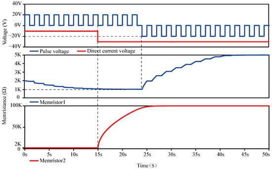
Figure 1.
The simulation results of memristors.
3. Modules of Circuit Design
3.1. Input Module
The input module is shown in Figure 2. The input module is used to filter out the noise interference in input signals. The input module can convert the complex target signal into an easily identifiable pulse signal. The module uses a simple circuit to process the initial image, which is convenient for subsequent detection and reduces the difficulty of classification. is the input signal without processing. is the processed input signal. is a voltage comparator. is a buffer. changes from to 0 V when the input voltage reaches 0 V from a positive voltage. The function of the output voltage of the input module is
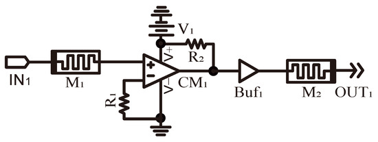
Figure 2.
Input module. is an input. . = = , and are memristors.
The initial memristance of is . If , the memristance of decreases to . If , the memristance of increases to . If , , and are constructed as a simple comparator. outputs when the non-inverting input voltage of is greater than the inverting input voltage of . can reduce signal distortion during transmission by providing low output impedance. It improves the waveform of the signal and maintains signal integrity. The initial memristance of is . The connection mode of is a reverse connection. When the applied voltage is greater than in , the memristance of increases from to in a short time. The voltage of is limited to a meager value. It can prevent excessive input voltage from damaging the circuit in this paper. The simulation results of the input module are shown in Figure 3. Input types 1 and 2 are triangle and trapezoid signals, respectively. Triangle and trapezoid signals become regular pulse signals after the filtration of the input module.
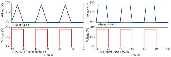
Figure 3.
The simulation results of input module.
3.2. Voltage Control Module
The circuit of the voltage control module is shown in Figure 4. The voltage control module in the circuit reflects the principle of classification. The voltage control module is designed for classification based on the loser-take-all mechanism. Three input signals are randomly assigned together for classification. – are randomly assigned to three groups. Voltage control Modules 1–9 are designed for primary classification by the loser-take-all mechanism. The output signals of primary classification are subjected to secondary classification. , and are inputs. is an OR gate. and are voltage comparators. is the output voltage of the voltage control module. The memristance of and is regulated by the output voltage of and , respectively. The ports of in and are connected to ground. The ports of in and are connected to . outputs the voltage of when the inverting port voltage exceeds the non-inverting port voltage. On the contrary, outputs 0 V. The principle of is the same as . The mathematical formula of is as follows:
The mathematical formula of is as follows:
M19, and are implemented as a basic amplifier. The mathematical formula is . If the memristance of increases to , drops to a very low value. The principle of is the same as .
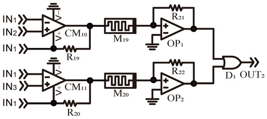
Figure 4.
Voltage control module. = = = = , and are memristors.
3.3. Selective Module
The selective module is shown in Figure 5. and are OR gates. – are precision operational amplifiers. and are voltage comparators. is a buffer. is the output voltage of the voltage control module. is the output voltage of the selective module. , and are implemented as a basic amplifier. The mathematical formula is . The mathematical formula of is . The mathematical formula of is . outputs when . outputs when . The mathematical formula of is
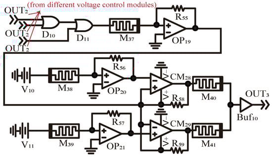
Figure 5.
Selective module. – are memristors. . , .
The selective module in the circuit receives the input signals from different voltage control modules. The input signals eliminated by voltage control modules can not output from the selective module. The selective module can protect the circuit against damage from excessive or inadequate voltage signals, thereby improving the reliability of the circuit. The output threshold of the circuit in this paper can be adjusted by the selective module. Adjustable voltage threshold can broaden the application range of the circuit.
3.4. Inhibition Module
The inhibition module is shown in Figure 6. The inhibition module in the circuit can inhibit the input signals by the loser-take-all mechanism. Relatively large input signals are inhibited, and the smallest input signals are the final output. Input signals in the inhibition module are from different selective modules. and are voltage comparators. is an AND gate. is a precision operational amplifier. is a voltage-controlled switch. The inverting input of the voltage-controlled switch is grounded. , and are implemented as a basic amplifier. The mathematical formula is . The mathematical formula of is
The output voltage of the inhibition module is .
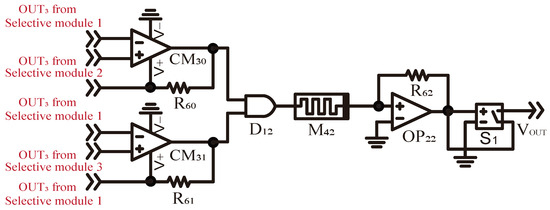
Figure 6.
Inhibition module. is a memristor. .
4. Circuit Design and Simulation Results
4.1. Memristor-Based Classification Circuit with the Loser-Take-All Mechanism
4.1.1. Diagram of the Complete Circuit
For a typical loser-take-all mechanism, the neurons in the network are interconnected and receive inputs from various sources. These inputs are processed, and the neuron with the lowest output is the “loser”. The network’s response is sparsified, meaning that only a small subset of neurons is activated. As shown in Figure 7, the memristor-based classification circuit with the loser-take-all mechanism in this paper contains nine inputs. – are randomly divided into three groups. The loser-take-all mechanism means that the output signal occurs only when the corresponding input does not have the greatest value among all inputs. For three inputs, the random guessing of which class an input belongs to has an accuracy probability of only 1/3. In contrast, the random guessing of which class it does not belong to has an accuracy probability of 2/3. The loser-take-all mechanism improves classification accuracy by identifying which category the input does not belong to. In the primary classification, – are classified out by the loser-take-all mechanism. – do not belong to the greatest class in –. In the secondary classification, – are classified by the loser-take-all mechanism. – do not belong to the greatest class in –. is the final output in –.
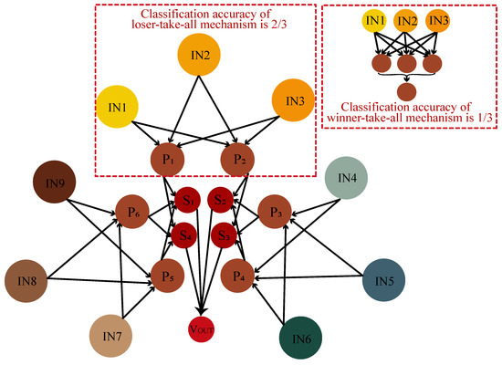
Figure 7.
Illustration of classification with the loser-take-all mechanism.
4.1.2. Complete Circuit
The memristor-based classification circuit with the loser-take-all mechanism is shown in Figure 8, in which the input module, the voltage control module and the selective module are connected to each other. – are different inputs. is the final output voltage.
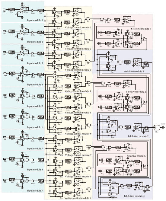
Figure 8.
Memristor-based classification circuit with the loser-take-all mechanism.
4.2. Simulation Results and Analyses
The memristor-based classification circuit with the loser-take-all mechanism is simulated with Cadence 17.2. As shown in Figure 9, – are nine inputs in the circuit. , and generate voltages of 18 V, 17 V and 16 V, respectively. , and generate voltages of 15 V, 14 V and 13 V, respectively. , and generate voltages of 12 V, 11 V and 10 V, respectively. The width of each pulse is 2 s, and the period is 4 s. – are the results of the primary classification in , and . , and output the voltage of 0 V. outputs the input voltage of . and output the input voltage of . is eliminated in the primary classification. – are the results of the primary classification in , and . , and output the voltage of 0 V. outputs the input voltage of . and output the input voltage of . is eliminated in the primary classification. – are the results of the primary classification in , and . , and output the voltage of 0 V. outputs the input voltage of . and output the input voltage of . is eliminated in the primary classification. The greatest values of the corresponding inputs are eliminated by the memristor-based classification circuit with the loser-take-all mechanism. At last, , , , , and are outputs of the primary classification. The simulation results of two inputs and four inputs are shown in Figure 10. and are the two inputs in the two-input simulation. and generate voltages of 10 V and 5 V, respectively. The width of each pulse is 2 s and the period is 5 s. The voltage of 5 V is the output based on the loser-take-all mechanism in the two-input simulation result. – are the four inputs in the four-input simulation. , , and generate voltages of 10 V, 8 V, 5 V and 3 V, respectively. The voltage of 3 V is the output based on the loser-take-all mechanism in the four-input simulation result. As shown in Figure 11, – are different inputs in the circuit. Classification Process 1 occurs from 0 s to 50 s. – represent different voltage levels and perform Primary Classification 1 in the initial classification. In Classification Process 1, – are 18 V-10 V, respectively. The nine inputs are classified into six outputs after Primary Classification 1. The six inputs are classified into the single output after Scondary Classification 1. outputs the voltage of 10 V. Classification Process 2 occurs from 50 s to 100 s. In Classification Process 2, – are 1 V-9 V, respectively. outputs the voltage of 1 V.
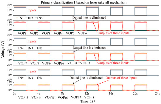
Figure 9.
The simulation result of Primary Classification 1.
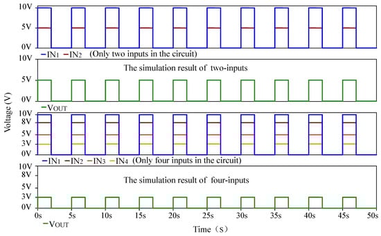
Figure 10.
The simulation results of two inputs and four inputs.
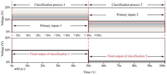
Figure 11.
The simulation result of the memristor-based classification circuit with the loser-take-all mechanism.
The simulation results illustrate the application of the loser-take-all mechanism in this circuit. The smallest part can be activated in primary classification and secondary classification. In this circuit, – undergo two rounds of classification. One of the nine inputs is ultimately activated based on the loser-take-all mechanism.
Monte Carlo Analysis
Figure 12 is the Monte Carlo analysis simulation results of inputs and outputs. The tolerance value of the resistance setting is , and the simulation times are 50. Vsin is the additional sinusoidal interference signal. The DC bias voltage of the sinusoidal interference signal is 0 V, and the AC amplitude is 0.2 V. The frequency of the sinusoidal interference signal is 50 Hz. The simulation results of are relatively stable and consistent across different tolerance values. The simulation results show that the circuit designed in this paper can run stably under tolerance values.
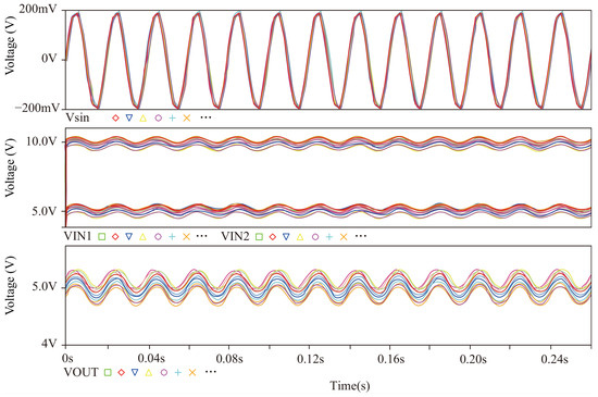
Figure 12.
Monte Carlo simulation results of inputs and outputs. The lines of different colors represent different inputs and outputs when performing the Monte Carlo analysis.
The power consumption and area of a CMOS circuit depend on the specific implementation and manufacturing process. The method of making an integrated circuit into a compatible platform mentioned in [45,46,47] is used to analyze the circuit in this paper. The calculation area formula of a single memristor is . represents the area of a single memristor, and f represents half of the minimum distance between two metal wires. Under technology, the areas of the input module, the voltage control module and the selective module are , and , respectively. Therefore, the area of the circuit in Figure 8 is about . Generally, the area and power consumption decrease with increasing integration density. In [48], the simulation report from Cadence shows that the average power consumption of the resistors and CMOS are 9.79 mW and 2.27 mW, respectively. The average power consumption of the voltage sources and capacitances are and 8.58 pW, respectively. In this paper, the power consumption of resistors and CMOS is considered in the majority. As shown in Table 3, the proposed circuit is compared with different circuits in area and power consumption. In this work, the circuit implements the functions of multiple recognition, signal processing, elimination of interference signal, simple construction and loser-take-all mechanism in classification circuits. Compared with other circuits [28,29,30,31,32], the proposed circuit can effectively operate with lower power consumption and smaller circuit area.
Table 3.
Comparison with several different papers. The symbol √ indicates that a work has this feature, while the symbol × indicates that the work does not have this feature.
5. Conclusions
In this paper, the memristor-based classification circuit with the loser-take-all mechanism is designed; it can be used for multi-class classification. The circuit is designed for multi-class classification, and the input signals of the circuit include nine signals. The circuit utilizes input modules, voltage control modules, and selective modules to realize the loser-take-all mechanism. Interference signals can be eliminated when the identified signal passes through the input modules. Voltage control modules and selective modules can handle the processed inputs. The final output signals are the classification results of the loser-take-all mechanism. Theoretical analysis and simulation results demonstrate that the circuit achieves multi-class classification based on the loser-take-all mechanism. The stability and robustness of the circuit are verified through Monte Carlo simulation. Additionally, the designed circuit exhibits low power consumption and small area. The design of the memristor-based classification circuit with the loser-take-all mechanism provides valuable insights for the advancement of hardware multi-class classification circuits.
Author Contributions
Conceptualization, G.H. and Y.X.; methodology, G.H.; software, Q.Y.; validation, G.H., Q.Y. and Y.X.; formal analysis, G.H.; investigation, Q.Y.; resources, Y.X.; data curation, Q.Y.; writing—original draft preparation, G.H.; writing—review and editing, Y.X.; visualization, G.H.; supervision, Y.X.; project administration, Q.Y.; funding acquisition, Y.X. All authors have read and agreed to the published version of the manuscript.
Funding
This work was supported in part by the National Natural Science Foundation of China (No. 62276239).
Data Availability Statement
Data will be made available on request from the corresponding author.
Conflicts of Interest
Author Yuanpeng Xu was employed by the company Xuchang Longgang Power Generation Co., Ltd. The remaining authors declare that the research was conducted in the absence of any commercial or financial relationships that could be construed as a potential conflict of interest.
References
- Taufique, Z.; Zhu, B.; Coppola, G.; Shoaran, M.; Altaf, M.A.B. A low power multi-class migraine detection processor based on somatosensory evoked potentials. IEEE Trans. Circuits Syst. II-Express Briefs 2021, 68, 1720–1724. [Google Scholar] [CrossRef]
- Cui, X.; Cao, J.; Wang, T.; Lai, X. Robust randomized autoencoder and correntropy criterion-based one-class classification. IEEE Trans. Circuits Syst. II-Express Briefs 2021, 68, 1517–1521. [Google Scholar] [CrossRef]
- Temel, T. High-performance current-mode multi-input loser-take-all minimum circuit. Electron. Lett. 2008, 44, 718–719. [Google Scholar] [CrossRef]
- Badel, S.; Schmid, A.; Leblebici, Y. CMOS realization of two-dimensional mixed analog–digital Hamming distance discriminator circuits for real-time imaging applications. Microelectron. J. 2008, 39, 1817–1828. [Google Scholar] [CrossRef]
- Maunu, J.; Laiho, M.; Paasio, A. A differential architecture for an online analog viterbi decoder. IEEE Trans. Circuits Syst. I-Regul. Pap. 2008, 55, 1133–1140. [Google Scholar] [CrossRef]
- Ohata, T.; Saito, T. Stability analysis of multi-phase synchronization in paralleled buck converters with winner-take-all and loser-take-all switching rules. IEEE J. Emerg. Sel. Top. Circuits Syst. 2015, 5, 345–353. [Google Scholar] [CrossRef]
- Sun, J.; Wang, Y.; Liu, P.; Wen, S.; Wang, Y. Memristor-based neural network circuit with multimode generalization and differentiation on Pavlov associative memory. IEEE Trans. Cybern. 2023, 53, 3351–3362. [Google Scholar] [CrossRef]
- Han, J.; Cheng, X.; Xie, G.; Sun, J.; Liu, G.; Zhang, Z. Memristive circuit design of associative memory with generalization and differentiation. IEEE Trans. Nanotechnol. 2023, 23, 35–44. [Google Scholar] [CrossRef]
- Wang, Z.; Shi, X.; Yao, X. A brain-inspired hardware architecture for evolutionary algorithms based on memristive arrays. ACM Trans. Des. Autom. Electron. Syst. 2023, 28, 82. [Google Scholar] [CrossRef]
- Sun, J.; Zhai, Y.; Liu, P.; Wang, Y. Memristor-based neural network circuit of associative memory with overshadowing and emotion congruent effect. IEEE Trans. Neural Netw. Learn. Syst. 2024. Early Access. [Google Scholar] [CrossRef]
- Han, J.; Wang, Q.; Chen, Z.; Sun, J.; Liu, G.; Zhang, Z. Memristive circuit design of mood-dependent memory with learning curve. AEU-Int. J. Electron. Commun. 2023, 170, 154801. [Google Scholar] [CrossRef]
- Sun, J.; Zhao, Y.; Wang, Y.; Liu, P. Memristor-based affective associative memory circuit with emotional transformation. IEEE Trans. Circuits Syst. II-Express Briefs 2024, 71, 4601–4605. [Google Scholar] [CrossRef]
- Rehman, M.M.; ur Rehman, H.M.M.; Kim, W.Y.; Sherazi, S.S.H.; Rao, M.W.; Khan, M.; Muhammad, Z. Biomaterial-based nonvolatile resistive memory devices toward ecofriendliness and biocompatibility. ACS Appl. Electron. Mater. 2021, 3, 2832–2861. [Google Scholar] [CrossRef]
- Sun, J.; Li, C.; Wang, Z.; Wang, Y. A memristive fully connect neural network and application of medical image encryption based on central diffusion algorithm. IEEE Trans. Ind. Inform. 2024, 20, 3778–3788. [Google Scholar] [CrossRef]
- Bao, H.; Li, H.; Hua, Z.; Xu, Q.; Bao, B. Sine-transform-based memristive hyperchaotic model with hardware implementation. IEEE Trans. Ind. Inform. 2022, 19, 2792–2801. [Google Scholar] [CrossRef]
- Li, S.; Ahn, C.K.; Guo, J.; Xiang, Z. Neural network-based sampled-data control for switched uncertain nonlinear systems. IEEE Trans. Syst. Man Cybern. 2021, 51, 5437–5445. [Google Scholar] [CrossRef]
- Han, J.; Cheng, X.; Xie, G.; Sun, J.; Liu, G.; Zhang, Z. Memristor-based neural network circuit of associative memory with occasion setting. IEEE Trans. Cogn. Dev. Syst. 2023, 16, 1016–1026. [Google Scholar] [CrossRef]
- Chen, Z.; Wang, X.; Yang, C.; Wang, Z.; Zeng, Z. Memristive circuit design for personalized emotion generation with memory and retrieval functions. IEEE Trans. Cogn. Dev. Syst. 2023. Early Access. [Google Scholar] [CrossRef]
- Sun, J.; Ma, Y.; Wang, Z.; Wang, Y. Dynamic analysis and cryptographic application of a 5D hyperbolic memristor-coupled neuron. Nonlinear Dyn. 2023, 111, 8751–8769. [Google Scholar] [CrossRef]
- Yang, G.; Zhang, X.; Moshayedi, A.J. Implementation of the simple hyperchaotic memristor circuit with attractor evolution and large-scale parameter permission. Entropy 2023, 25, 203. [Google Scholar] [CrossRef]
- Sun, J.; Xu, W.; Liu, P.; Wang, Y. Design and implementation of pavlovian associative memory based on DNA neurons. IEEE Trans. Neural Netw. Learn. Syst. 2024. Early Access. [Google Scholar] [CrossRef] [PubMed]
- Tamba, V.K.; Biamou, A.L.M.; Pham, V.T.; Grassi, G. Multistable memristor synapse-based coupled bi-hopfield neuron model: Dynamic analysis, microcontroller implementation and image encryption. Electronics 2024, 13, 2414. [Google Scholar] [CrossRef]
- Mladenov, V.; Kirilov, S. A memristor neural network based on simple logarithmic-sigmoidal transfer function with MOS transistors. Electronics 2024, 13, 893. [Google Scholar] [CrossRef]
- Morell, A.; Machado, E.D.; Miranda, E.; Boquet, G.; Vicario, J.L. Ternary neural networks based on on/off memristors: Set-up and training. Electronics 2022, 11, 1526. [Google Scholar] [CrossRef]
- Sun, J.; Wang, Y.; Liu, P.; Wen, S.; Wang, Y. Memristor-based circuit design of PAD emotional space and its application in mood congruity. IEEE Internet Things J. 2023, 10, 16332–16342. [Google Scholar] [CrossRef]
- Chen, B.; Liu, F.; Iu, H.H.C.; Bao, H.; Xu, Q. Memristive neural network circuit of operant conditioning with reward delay and variable punishment intensity. IEEE Trans. Circuits Syst. II-Express Briefs 2024, 71, 1002–1006. [Google Scholar] [CrossRef]
- Zhao, H.; Liu, Z.; Tang, J.; Gao, B.; Qin, Q.; Li, J.; Zhou, Y.; Yao, P.; Xi, Y.; Lin, Y.; et al. Energy-efficient high-fidelity image reconstruction with memristor arrays for medical diagnosis. Nat. Commun. 2023, 14, 2276. [Google Scholar] [CrossRef]
- Wu, A.; Wen, S.; Zeng, Z. Synchronization control of a class of memristor-based recurrent neural networks. Inf. Sci. 2012, 183, 106–116. [Google Scholar] [CrossRef]
- Sebastianelli, A.; Zaidenberg, D.A.; Spiller, D.; Saux, B.L.; Ullo, S.L. On circuit-based hybrid quantum neural networks for remote sensing imagery classification. IEEE J. Sel. Top. Appl. Earth Obs. Remote Sens. 2022, 15, 565–580. [Google Scholar] [CrossRef]
- Lu, Y.; Yang, B.; Gao, Y.; Xu, Z. An automatic sorting system for electronic components detached from waste printed circuit boards. Waste Manag. 2022, 137, 1–8. [Google Scholar] [CrossRef]
- Yildirim, M. Analog circuit implementation based on median filter for salt and pepper noise reduction in image. Analog Integr. Circuits Process. 2021, 107, 195–202. [Google Scholar] [CrossRef]
- Dou, G.; Zhao, K.; Guo, M.; Mou, J. Memristor-based LSTM network for text classification. Fractals 2023, 31, 2340040. [Google Scholar] [CrossRef]
- Chen, Z.; Zhang, J.; Wen, S.; Li, Y.; Hong, Q. Competitive neural network circuit based on winner-take-all mechanism and online hebbian learning rule. IEEE Trans. Very Large Scale Integr. Syst. 2021, 29, 1095–1107. [Google Scholar] [CrossRef]
- Elhamdaoui, M.; Rziga, F.O.; Mbarek, K.; Besbes, K. The EGM model and the winner-takes-all (WTA) mechanism for a memristor-based neural network. Arab. J. Sci. Eng. 2023, 48, 6175–6183. [Google Scholar] [CrossRef]
- Feng, Z.; Liu, Y.; Li, T.; Liu, Z.; Ding, H.; Cao, X. Design of winner-takes-all circuits in competitive neural networks. J. Phys. Conf. Ser. IOP Publ. 2022, 2356, 012016. [Google Scholar] [CrossRef]
- Wen, S.; Xie, X.; Yan, Z.; Huang, T.; Zeng, Z. General memristor with applications in multilayer neural networks. Neural Netw. 2018, 103, 142–149. [Google Scholar] [CrossRef]
- Wang, J.; Lin, Y.; Hu, C.; Zhou, S.; Gu, S.; Yang, M.; Ma, G.; Yan, Y. A kind of optoelectronic memristor model and its applications in multi-valued logic. Electronics 2023, 12, 646. [Google Scholar] [CrossRef]
- Kvatinsky, S.; Friedman, E.G.; Kolodny, A.; Weiser, U.C. TEAM: Threshold adaptive memristor model. IEEE Trans. Circuits Syst. I Reg. Pap. 2012, 60, 211–221. [Google Scholar] [CrossRef]
- Zhang, Y.; Li, Y.; Wang, X.; Friedman, E.G. Synaptic characteristics of Ag/AgInSbTe/Ta-based memristor for pattern recognition applications. IEEE Trans. Electron Devices 2017, 64, 1806–1811. [Google Scholar] [CrossRef]
- Kumar, A.; Chaturvedi, B. A high-quality and space-efficient design for memristor emulation. Electronics 2024, 13, 3331. [Google Scholar] [CrossRef]
- Peng, S.; Shi, H.; Li, R.; Xiang, Q.; Dai, S.; Li, Y. Simulink modeling and analysis of a three-dimensional discrete memristor map. Symmetry 2024, 16, 990. [Google Scholar] [CrossRef]
- Jia, F.; He, P.; Yang, L. A novel coupled memristive izhikevich neuron model and its complex dynamics. Mathematics 2024, 12, 2244. [Google Scholar] [CrossRef]
- Shatnawi, M.T.; Khennaoui, A.A.; Ouannas, A.; Grassi, G.; Radogna, A.V.; Bataihah, A.; Batiha, I.M. A multistable discrete memristor and its application to discrete-time FitzHugh—Nagumo model. Electronics 2023, 12, 2929. [Google Scholar] [CrossRef]
- Zhang, Y.; Wang, X.; Li, Y.; Friedman, E.G. Memristive model for synaptic circuits. IEEE Trans. Circuits Syst. II Exp. Briefs 2016, 64, 767–771. [Google Scholar] [CrossRef]
- Xia, L.; Li, B.; Tang, T.; Gu, P.; Chen, P.Y.; Yu, S.; Cao, Y.; Wang, Y.; Xie, Y.; Yang, H. MNSIM: Simulation platform for memristor-based neuromorphic computing system. IEEE Trans. Comput. Aided Des. Integr. Circuits Syst. 2017, 37, 1009–1022. [Google Scholar] [CrossRef]
- Shi, X.; Zeng, Z.; Yang, L.; Huang, Y. Memristor-based circuit design for neuron with homeostatic plasticity. IEEE Trans. Emerg. Top. Comput. Intell. 2018, 2, 359–370. [Google Scholar] [CrossRef]
- Dong, M.; Zhong, L. Nanowire crossbar logic and standard cell-based integration. IEEE Trans. Very Large Scale Integr. Syst. 2009, 17, 997–1007. [Google Scholar] [CrossRef]
- Hong, Q.; Yan, R.; Wang, C.; Sun, J. Memristive circuit implementation of biological nonassociative learning mechanism and its applications. IEEE Trans. Biomed. Circuits Syst. 2020, 14, 1036–1050. [Google Scholar] [CrossRef]
Disclaimer/Publisher’s Note: The statements, opinions and data contained in all publications are solely those of the individual author(s) and contributor(s) and not of MDPI and/or the editor(s). MDPI and/or the editor(s) disclaim responsibility for any injury to people or property resulting from any ideas, methods, instructions or products referred to in the content. |
© 2024 by the authors. Licensee MDPI, Basel, Switzerland. This article is an open access article distributed under the terms and conditions of the Creative Commons Attribution (CC BY) license (https://creativecommons.org/licenses/by/4.0/).