Abstract
Due to the deformation of ships, it becomes difficult to ensure the accuracy of attitude measurement in typical areas on the deck, which seriously impacts the safety and operational efficiency of shipborne equipment. To address this issue, this paper presents a parameter identification method for dynamic deformation models based on angle increment differences and introduces the related vector machine (RVM) algorithm for online estimation of dynamic deformation model parameters. In view of the truncation error and non-Gaussian noise of the model, this article proposes a dynamic attitude measurement method based on model predictive filtering (MPF), constructs a dynamic measurement model using Rodrigues parameters in an inertial frame, and designs a maximum correlation entropy (MCE) robust filter to achieve robust estimation of deck dynamic deformation. The performance of the method is verified through simulation analysis and shipborne experiments. The comparative results indicate that, compared with existing methods, the proposed improved deck dynamic attitude measurement algorithm based on model prediction (IDAM) can substantially enhance the accuracy of attitude measurement in the presence of deck dynamic deformations.
1. Introduction
To measure the attitude in the area equipped with shipborne equipment on the deck, a sub-inertial measurement unit (IMU) can be installed, and the attitude information can be derived from the inertial measurement information [1,2]. But the sub-optimal performance of the sub-IMU fails to meet the accuracy requirement for attitude, and it is necessary to use the ship’s main inertial navigation information for auxiliary measurement [3,4,5]. However, due to the fact that the ship is not an ideal rigid body, it may undergo deformation under external influences such as sunlight and wave impact [6,7]. The deformation of the ship manifests as static and dynamic types [8]. The static deformation of the ship can be estimated and regarded as the installation error angle between the main and sub-inertial navigation systems. The dynamic deformation of the ship will directly affect the gyroscope output of the inertial measurement unit and result in additional errors caused by changes of the dynamic lever arm, thereby affecting the attitude calculation accuracy. In order to achieve accurate measurement of the dynamic attitude in typical deck areas, it is necessary to consider the influence of ship deck deformation.
The method based on inertia matching is easy to implement and can calculate and measure the deformation angle of ships with high accuracy. However, to obtain high-precision measurements, it is necessary to identify the parameters of the dynamic deformation model. The original method of parameter identification for dynamic flexural deformation models involves processing historical data of deformation measurements. However, due to the influence of environmental factors, the parameters of dynamic models are constantly changing, so the parameters obtained from prior data analysis may not meet the actual needs [9]. Zheng et al. [10] proposed an online receding horizon identification method for nonlinear ship motion systems. The Tufts–Kumaresan method was introduced to compute unknown parameters of the dynamic flexure model using the angular increment correlation function [11]. Yu et al. [12] employed the particle swarm optimization (PSO) algorithm to form a complete online identification for ship deformation angle measurement model. The support vector regression (SVR) algorithm-based identification method was presented for the estimation of parameters in the ship dynamic model [13]. Wang et al. [14] designed an improved whale optimization algorithm (WOA) based on logic mapping to perform parameter identification.
The dynamic deformation of the deck can be described by a second-order Markov process. However, the model inevitably has a truncation error, and the dynamic deformation estimated by the filter will also be subject to estimation errors due to the truncation error. In addition, the model is not driven by ideal Gaussian white noise due to the impact interference of the wave environment. Therefore, based on the above analysis, in the process of measuring the dynamic attitude of the deck, it is necessary to consider the effects of model truncation error and non-Gaussian noise. A multi-model adaptive hull deformation estimation algorithm was proposed to address the uncertainty of system parameters and the statistical characteristics of measurement noise [15]. Ren et al. [16] proposed a dynamic filter algorithm combining wavelet and a Kalman filter for dynamic inertial measurement, in which the wavelet method is used to remove the outliers in the acquired data, and the Kalman filter effectively reduces the influence of white noise. An adaptive dynamic particle swarm optimization (ADPSO) algorithm and a bidirectional long short-term memory (BiLSTM) neural network-based prediction model were proposed and applied to accurately predicting ship motion attitude [17]. The neural network Kalman filter (NNKF) was introduced for real-time hull deformation calculation to further reduce the nonlinear error of the system. This method can accurately measure the hull deformation in real time and effectively suppress the nonlinear error caused by the large misalignment angle [18]. Traditional Kalman filtering regards model errors as process noise, which has limitations in its application. To circumvent this problem, the filtering estimator based on MPF was derived and treated as a suitable estimator for random measurement processes [19]. MPF realizes the error estimation of the system model with good robust stability [20,21]. In [22], model predictive filter technology was applied in the transfer alignment, which can estimate deformation and compensate alignment errors. A novel model predictive-based unscented Kalman filter (MP-UKF) was proposed to predict the dynamic model error persistently and correct the filtering procedure of UKF online [23].
However, traditional inertial measurement methods from our previous work cannot be directly applied to the dynamic attitude measurement of a deck with deformation because of the following reasons: (1) The method based on inertia matching can accurately calculate and measure the deformation angle of ships, and the most crucial aspect is how to accurately identify the parameters of the dynamic deformation model. The existing methods cannot meet practical needs. (2) The traditional Kalman filter considers the model error as process noise, and models that approximate dynamic deformation using second-order Markov processes inevitably have truncation errors. In addition, due to the impact interference of the wave environment, the model is not driven by ideal Gaussian white noise, and the criterion of minimum mean square error based on Gaussian noise cannot provide robust estimation performance. (3) The traditional linear error model for small misalignment angles cannot be applied to situations with large misalignment angles. However, nonlinear models based on large misalignment angles also involve excessive redundant calculations in the nonlinear filtering process. Therefore, it is necessary to study the system error model that is insensitive to the magnitude of misalignment angles.
The remaining structure of this paper is organized as follows: The dynamic deformation model of the deck is established in Section 2. The online parameter identification for the dynamic deformation model based on angle increment difference is described in Section 3. The dynamic attitude measurement method for the deck based on model predictive filtering is presented in Section 4. The simulation analysis and shipborne experiment verification of the proposed method are carried out in Section 5 and Section 6, respectively. Finally, Section 7 summarizes the main conclusions.
The contributions of this paper can be summarized as follows: (1) The related vector machine algorithm was applied to the parameter identification of the dynamic deformation model based on angle increment difference. (2) Considering the truncation error of the model and the influence of non-Gaussian noise, this paper designed a maximum correlation entropy robust filter based on MPF. In order to estimate and compensate for filtering model errors, the maximum correlation entropy was introduced as an optimization criterion to achieve robust estimation of deck dynamic deformation angle. (3) This method constructed the filter model based on Rodrigues parameters in an inertial frame, which is suitable for any misalignment angle situation, eliminating the calculation error of the sub-inertial navigation system. (4) All experimental data were obtained from the navigation experimental platform. Both simulation analysis and online verification were conducted to validate the effectiveness of the proposed method.
2. Dynamic Deformation Analysis and Modeling of the Deck
The deck undergoes deformation under the influence of the external environment. The deformation angle of deck can generally be divided into static deformation angle and dynamic deformation angle as follows:
where is the static deformation angle of the deck and is the dynamic deformation angle of the deck over time. The static deformation angle is considered to be constant or to slowly change, and the model construction of such deformation is relatively simple. In contrast, dynamic deformation shows higher frequency and greater complexity. The following models were used to describe the static and dynamic deformation angles.
- (1)
- The static deformation of the deck
Under the combined action of multiple external forces, the deck undergoes bending deformation, resulting in static deformation angles. In fact, the deck deformation measurement system measures the real-time relative misalignment angle between the IMU in the deck area and the ship’s main inertial navigation IMU, which includes the static and dynamic deformation of the ship and the system installation error angle. The installation error angle between two sets of IMUs can be considered a constant value, and its statistical characteristics are similar to the static deformation angle of the deck. Consequently, the static deformation angle and the system installation error angle were combined into the static deformation angle. Generally, the static deformation angle changes slowly and can be approximated as a constant value as described in Equation (2).
- (2)
- The dynamic deformation of the deck
Compared with the static deformation, the dynamic deformation changes more rapidly. The dynamic deformation is primarily caused by the wind and waves, which can be regarded as a random variable under random external disturbances, akin to the Markov process for white noise. Therefore, using second-order Markov process models as the ship’s dynamic deformation model is usually suitable for most scenarios. The deformation models in three directions are considered independent of each other, and the dynamic deformation angle can be given as follows [24,25]:
where is the deflection angle; is the rate of deflection deformation angle; and are the white noise and its variance; is the relevant time; and is the variance of the deflection deformation angle.
However, the lever arm between the main and sub-IMUs will have an impact on the inertial measurement information. Specifically, the fixed arm length between the two IMUs remains unchanged. Due to the influence of deck dynamic deflection deformation, it can lead to dynamic changes in lever-arm length, resulting in dynamic lever-arm error. Figure 1 shows the schematic diagram of the length variation of the dynamic lever arm.
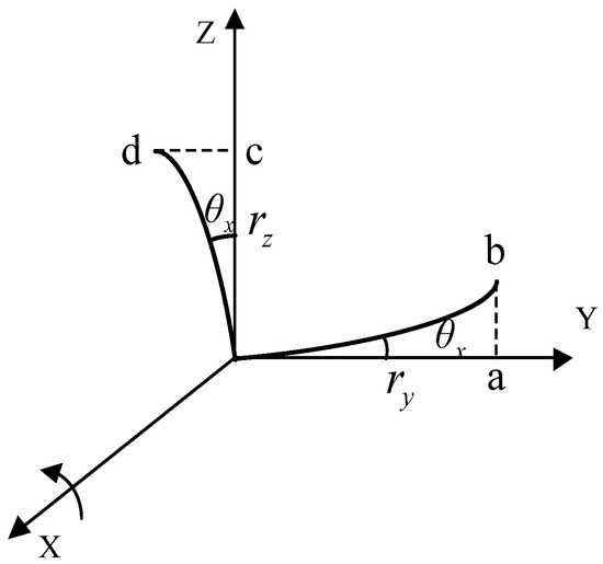
Figure 1.
Schematic diagram of changes in the dynamic lever-arm length.
Assuming the fixed lever-arm vector is and the deflection angle vector is in the main inertial vehicle coordinate system (m system), we can obtain
Similarly, the change in the component of the lever arm caused by the dynamic lever -arm and is presented in the following Equation
The dynamic lever can be described as follows:
Equation (7) gives the first and second derivatives of the dynamic lever-arm vector.
3. Online Parameter Identification of the Dynamic Deformation Model Based on Angle Increment Difference
To achieve a high-precision dynamic deformation model, a dynamic deflection deformation model parameter identification method based on the difference in angular increment is proposed, in which an optimization model was constructed based on the autocorrelation function of the angle increment difference between two sets of IMUs, and the related vector machine algorithm was applied for online parameter estimation. Finally, the estimated dynamic deflection parameters were applied to the filtering model based on inertia matching to estimate the deformation angle. The online identification process of dynamic deformation model parameters is shown in Figure 2.
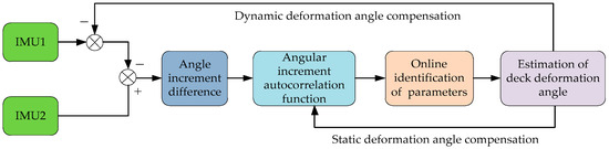
Figure 2.
Online identification process of dynamic deformation model parameters.
3.1. Derivation and Analysis of Correlation Functions Based on Angular Increment Difference
The dynamic deflection angle information is contained in the angle increment output difference of the IMU and presented in the form of exponentially decaying sine signals (EDS). In order to obtain accurate model parameters for dynamic deformation angle, the relationship between the output of the gyroscope and the dynamic deformation angle is crucial. To estimate the model parameters using online estimation methods, the relationship between the output of the gyroscope and the dynamic deformation angle needs to be derived. The angular velocity is output by the gyroscope, and the relationship between angular increment and dynamic deformation angle parameters can be calculated using the output data of the main and sub-inertial navigation system gyroscopes. Specifically, it is assumed that both the main IMU and sub-IMU of a ship can be sensitive to the projection of the ship’s inertial angular velocity on the frame and frame, represented by and . According to [26], the angular velocity matching relationship is as follows:
In the case of small deformation angles, we can obtain
The static deformation angle is treated as a constant value. When the deformation is regarded as a linear model, the difference in angular velocity between the main and sub-IMU is expressed as follows:
where
Integrating both sides of Equation (10) in the k-th sampling simultaneously yields
where is the sampling period.
By sorting out Equation (12), two sets of angular increment matching equations for inertial navigation within k sampling cycles can be obtained.
For Equation (13), and represent the angular increments of IMU1 and IMU2 within a single sampling period, respectively. By , Equation (13) can be rewritten as follows:
By estimating the static deformation angle , the term in Equation (14) is compensated online and we obtain
Further, Equation (15) can be approximated as follows:
When the correlation time τ ≥ 0, the correlation function of the dynamic deformation angle can be expressed as follows:
where .
The following definition is made in terms of the above Equation.
Combining Equation (17) and Equation (18) yields
According to the operation rule of the correlation function, the correlation function of discrete angular increments can be expressed as
Meanwhile, similar to the dynamic deformation angle model, the correlation function of can be expressed as follows:
Equation (22) can be further organized to obtain
where
It can be seen that Equation (23) has a similar form to the exponential sinusoidal attenuation signal. If the parameters , , and are solved by Equation (21), the first two terms present the attenuation factor and dominant frequency of the dynamic deflection model. By inputting the above parameters into Equation (24), can be calculated.
3.2. Online Identification of Dynamic Deformation Model Parameters Based on the RVM Algorithm
RVM is based on the structure of prior parameters and the automatic relevance determination theory to establish a sparse model under the Bayesian framework. Compared to SVM, the computational complexity of the kernel function is significantly reduced, and there is no need for the selected kernel function to satisfy the Mercer condition [27].
It is given that samples are , and the regression function is given by
where is the weight vector; is the threshold value; and is the kernel function.
Because the target sample is independent, the likelihood function can be denoted as follows:
where is a × order structural matrix composed of the kernel function.
According to the Bayesian framework, the prior distribution can be described as
where is the super parameter vector.
By Bayesian inference, the posterior distribution satisfies the following Equation
where the posterior mean and variance can be calculated as follows:
where .
By the edge integration of weights, the likelihood distribution of output is obtained by
We can obtain the edge likelihood distribution of hyperparameter, that is
where . is an identity matrix.
Updated and are determined by Equation (32).
where is the i-th element value of ; and and are the i-th diagonal value of .
and are updated by Equation (32) until the convergence condition presented as Equation (33) is met.
where the first term is the sum of measurement errors, and the second term is the regularization term. Figure 3 shows the flowchart of the RVM algorithm.
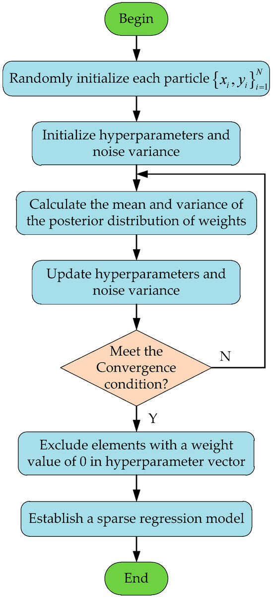
Figure 3.
The flowchart of the RVM algorithm.
Using the RVM algorithm for dynamic deformation model parameter identification involves deriving the autocorrelation function form of the difference in the output angle increment of two sets of IMUs. In the process of simplifying the angle increment difference , online compensation is implemented for . The autocorrelation function of the angle increment difference is obtained to identify the parameters of the dynamic deformation model by comparing Equations (21) and (23). The related vector machine algorithm is then selected to assist in establishing the algorithm model using the general form of exponentially decaying sine signals, and the parameters are reasonably set to complete the online parameter identification. As shown above, the specific process of online identification of dynamic deformation model parameters is as follows:
- (1)
- Calculate the angular increment output difference of two sets of IMUs in each sampling cycle and compensate for . The first static deformation angle can be roughly determined by the coarse alignment, and then estimated by the deformation algorithm.
- (2)
- Solve the numerical value of the autocorrelation function .
- (3)
- Substitute into the RVM algorithm and use Equation (33) for parameter identification.
- (4)
- Apply the identified parameters to the angular velocity matching algorithm for deformation angle estimation, substitute the estimated deformation angle back in step (1), and proceed to the next step of calculation.
4. Dynamic Attitude Measurement Method for Deck Based on Model Predictive Filtering
To solve the problems of truncation error and non-Gaussian noise in the dynamic attitude deformation angle model of the deck, this paper proposes a dynamic attitude measurement method for the deck based on model prediction filtering. By designing a robust maximum correlation entropy filter based on model prediction, estimating and compensating for the filtering model error, a robust estimation of the deck deflection deformation is achieved.
4.1. Model Error Analysis and Prediction Estimation
Model predictive filtering is an advanced filtering method proposed in recent years that overcomes the limitation of traditional Kalman filtering that assumes model errors as process noise processing. The biggest advantage of model predictive filtering is its fast calculation speed. It estimates observable low-state variables as model errors and uses observations to correct uncertain errors. In addition, since the model predicts the filtering equation through analytical expressions and does not have an iterative inversion process, it can reduce system dimensionality, accelerate calculation speed, and improve real-time performance while ensuring high system accuracy [22,23].
Specifically, the principle of predictive filtering involves using the predicted output of the filter to track the actual observed output in real time, thereby estimating the model error of the system. Firstly, the system state space differential model is derived from differential equations and is as follows:
where is the system status; is the state transition matrix; is the system noise vector; is the measure matrix; is the external measurement vector; and is the measurement noise. Representing the state estimation value and corresponding measurement prediction value with and , respectively, and the measurement model is obtained by the Taylor expansion
where
where is the lowest order that appears in the differentiation of the i-th component; ; is the k-th Lie derivative; and is the i-th column in . The definition of the predictive filtering performance indicator function is
where is the positive semi-definite weighting matrix for model error.
The estimated model error that satisfies the performance metric of Equation (39) within time can be designed as
According to Equation (40), can be calculated and compensated in the state transition model.
4.2. Design of Maximum Correlation Entropy Robust Filter Based on Model Prediction
In the model of the dynamic deformation angle of the deck mentioned above, it is assumed that the noise follows a Gaussian probability density function (PDF). However, due to the impact of wave environments and other external interferences from the ocean environment, the model is not driven by ideal Gaussian white noise and exhibits a non-Gaussian distribution. Compared to the minimum mean square error (MMSE) criterion based on Gaussian noise, the maximum correlation entropy criterion offers better robust estimation performance in non-Gaussian situations by capturing high-order moments of information. Therefore, this paper combines model prediction filtering and employs MCE as the optimal estimation criterion instead of MMSE to achieve robust and accurate estimation of the dynamic deformation angle of the deck.
The model error vector estimated by Equation (40) is used to compensate for the state prior mean as follows:
where is the transfer matrix for model error.
Furthermore, the covariance matrix of the state prior mean is calculated as follows:
The measurement update process is based on maximizing the correlation entropy between state prior and measurement information, rather than minimizing the mean square error of state estimation. Specifically, the measurement prediction information is calculated as follows:
Using Equation (44), the cost function is built as
where is the square of the weighted Mahalanobis distance with A as the weight matrix.
The Gaussian kernel function is defined as follows:
where is the kernel width and the optimal estimation based on maximum correlation entropy is obtained through the following objective function:
The optimization problem is solved by the following Equation:
where
By reorganizing Equation (47), we obtain
Because the state–transition model in inertial measurement systems is constructed accurately, the prior information about the state is accurate. In addition, a correlation entropy matrix was constructed to replace the correlation entropy scalars of each measurement information. Therefore, through further sorting, the mean and covariance matrix of the posterior estimation of the state can be obtained as follows:
where
4.3. Dynamic Measurement Model Based on Rodrigues Parameters in Inertial Frames
Due to the presence of the lever arm between the main IMU and sub-IMU, the dynamic deformation angle will introduce an error in the dynamic lever arm. Therefore, it was necessary to consider the influence of the dynamic lever arm. The measurement relationship between the main IMU and sub-IMU is provided in the inertial frame. The projection relationship of the specific force sensitive to the main IMU and sub-IMU under the influence of the lever-arm effect in the geocentric inertial frame is presented as follows:
where is the coordinate transformation matrix from the main inertial coordinate system to the geocentric inertial coordinate system; is the output of the main IMU’s gyroscope; is the acceleration caused by the rigid lever arm; and is the acceleration caused by the dynamic lever arm. According to Equation (54), after compensating for the acceleration of the rigid lever arm, we obtain
where is the specific force information of main IMU after compensating for the acceleration of the rigid lever arm; is the dynamic arm acceleration caused by deflection deformation; and , and are represented as follows:
Considering the influence of the lever-arm effect, the angular velocity relationship measured by the main IMU’s and sub-IMU’s gyroscope in the inertial frame is defined as follows:
where is the projection of the sub-IMU’s gyroscope in the inertial frame; is the value of the main IMU’s gyroscope; is the rotational angular velocity of the sub-IMU relative to the main IMU; and can be regarded as the deflection deformation angular velocity.
The main inertial vehicle coordinate system (m) and sub-inertial vehicle coordinate system (s) were fixed at the initial moment of transfer alignment, and the inertial solidification coordinate system, and , could be obtained, respectively. The coordinate transformation matrix between them is a time-varying matrix that can be calculated from the output of the main IMU’s gyroscope . According to the directional cosine matrix differential equation, we can obtain
Similarly, the transformation matrix can be represented as follows:
where is the computational inertial solidification coordinate system and is the output of sub-IMU’s gyroscope.
For the short-term alignment process, this tracking error can be considered a small amount, and there are
where is the constant zero bias of the sub-IMU’s gyroscope and is the random noise of the sub-IMU’s gyroscope.
After accurately fixing the length of the arm of the main and sub-inertial navigation systems, the rigid arm acceleration compensation was applied to the main inertial navigation system. The specific force after compensation is denoted as . can be projected to the system by as follows:
Similarly, the output of sub-IMU’s accelerometer can be transformed and described in system as
where is the constant zero bias of the sub-IMU’s accelerometer and is the random noise of the sub-IMU’s accelerometer.
If Equation (62) is expanded and high-order small quantities are ignored, we can obtain
Combining Equations (55), (61), and (63) yields
where is a constant matrix and represents the directional cosine matrix corresponding to the installation error angle between the main and sub-inertial vehicle coordinate systems at the initial moment of alignment.
Similarly, for the output of the main and sub-IMU’s gyroscope, we obtain
where
can be represented by Rodrigues vectors . According to the Cayley transformation, the relationship between the two satisfies the following Equation
By substituting Equation (67) into Equations (64) and (65), it can be concluded that
where and .
The right-hand side of Equations (68) and (69) contain the Rodrigues vectors corresponding to the installation error angles between the main IMU and sub-IMU. Therefore, the specific force (,) and angular velocity (,) of the main IMU and sub-IMU can be used as matching variables to construct the corresponding matching equations. Since there is no small angle assumption for the installation error angle during the derivation process, this matching equation is suitable for the transfer alignment process with a large misalignment angle.
The specific force and angular velocity outputs of the sub-IMU contain random noise disturbances, such as dynamic deflection deformation and measurement noise, which affect the matching accuracy in Equations (68) and (69). The smoothing characteristics of the integration process can attenuate random noise, improve the signal-to-noise ratio of measurement information, and improve the performance of misalignment angle estimation. However, although integral operation can enhance the anti-interference ability against random noise to a certain extent, it also complicates the transfer process from measurement information to state variables. Therefore, only the specific forces of the main IMU and sub-IMU in the inertial solidification coordinate system were selected for integration.
Specifically, integrating Equation (68) yields
where
Because is a constant matrix, the Rodrigues parameters corresponding to satisfy the following differential Equation:
Except for the constant drift of sub-inertial gyroscopes and the constant bias of accelerometers, the integration of dynamic arm acceleration , deflection angle , and angular velocity in system were selected as state variables. Equation (73) gives the definition of state vector.
Therefore, based on the above derivation, the system state differential equation was constructed as follows:
where the process noise , and the state transition matrix F is represented as
where
The process noise driving matrix G is represented as follows:
According to Equations (69) and (70), the measurement equation can be constructed as follows:
where is the measurement noise caused by the integration of residual errors and inertial device errors. Compared with the ship’s deformation angle measurement model based on angular velocity matching, this model does not require the initial parameters binding and strapdown calculation of the main IMU. It reduces the computational workload while suppressing the influence of compensating deflection deformation and dynamic arm errors, thereby enhancing the real-time performance of the calculation.
5. Simulation Experiment and Analysis
To verify the proposed method, we simulated and generated the ship’s motion attitude, IMU data, dynamic deformation angle, and other data through the following simulation conditions.
- (1)
- The initial latitude was set to 45° and the initial longitude was set to 126°. The motion state of the ship was to move forward with a constant speed of 20 knots. The initial roll angle was 0°, the initial pitch angle was also 0°, and the initial heading angle was 45°. The ship’s sway motion satisfies Equation (79)
- (2)
- The constant the gyroscope drift was set to 0.01°/h, the angle random walk to 0.001°/, the constant zero deviation of the accelerometer to 50 ug, and the acceleration random walk to 10 ug/. The installation error angle of IMU is 5″, and the scale factor error was 5 ppm. The calculation frequency was set to 100 Hz, and the initial horizontal misalignment angle and azimuth misalignment angle were 1′, and 5′, respectively.
- (3)
- The static deformation angle was set to a constant value [10′ 10′ 30′], and the dynamic deformation angle was generated using a second-order Markov model as follows:where is zero-mean Gaussian white noise. The variance of the deflection angle was set to , and the time related to the deflection angle was set to . The fixed arm length was set to .
- (4)
- Compare the proposed improved deck dynamic attitude measurement algorithm (IDAM) based on model prediction with the following common existing methods to verify the effectiveness of the proposed algorithm regarding the support vector regression-based algorithm for deck dynamic attitude measurement (SVRAM) [12] and the whale optimization-based algorithm for deck dynamic attitude measurement (WOAM) [13]. The root mean square error (RMSE) was used as a quantitative indicator to evaluate the accuracy of the different measurement methods and was defined as follows:where and represent the estimated state value and the true value of the state.
The CPU configuration of simulation computer was an Intel Core i5-1135G7 (2.4 GHz) and the simulations were run using Microsoft Visual Studio 10.0 software.
The estimation of deflection angle using different methods is shown in Figure 4. Figure 5 and Figure 6 give the attitude estimation errors and its RMSE values with the different methods, respectively.
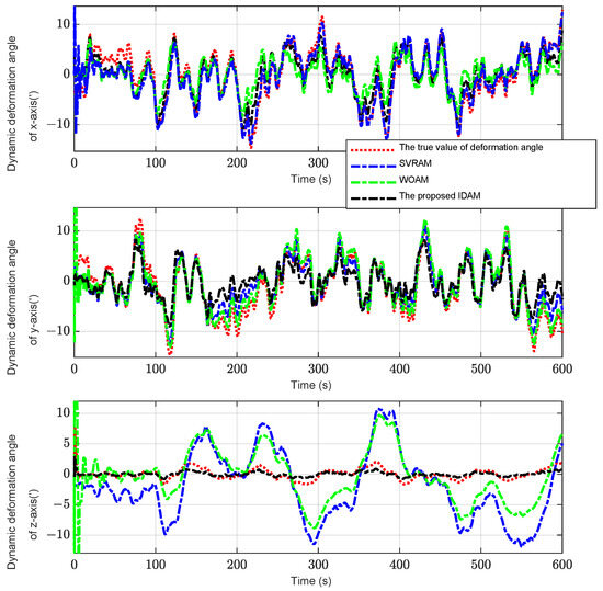
Figure 4.
Estimation results of the deflection angle with different methods.
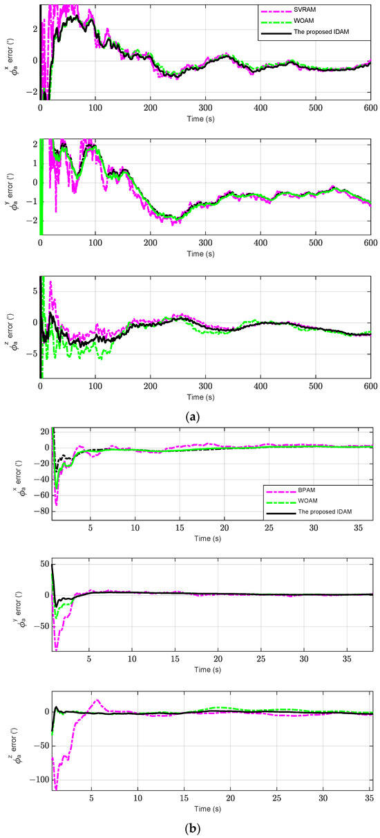
Figure 5.
The error of attitude error angle estimation with different methods; (a) overall view of attitude error angle estimation; (b) partial enlarged drawing of attitude error angle estimation.
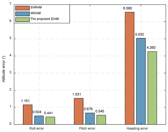
Figure 6.
Attitude error angle estimation error represented by RMSE.
It can be concluded from Figure 4 that the proposed algorithm can track and estimate the dynamic deformation angle more effectively compared to the SVRAM and WOAM methods, especially for the estimation of the z-axis dynamic deformation angle. Furthermore, as shown in Figure 5 and Figure 6, the proposed IDAM method significantly improves the accuracy of deck attitude measurement with accurate estimation of dynamic deformation angles and effective implementation of model prediction filtering. For the z-axis attitude, the estimated RMSE of the IDAM was 4.260′. Compared with the 6.560′ and 5.032′ of SVRAM and WOAM methods, respectively. Thus, the estimation accuracy decreased by 35.06% and 15.34%, respectively, indicating that the proposed algorithm can effectively improve the attitude measurement accuracy under deck dynamic deformation.
6. Shipborne Experiment and Analysis
To further verify the effectiveness and reliability of the proposed method, a shipborne experiment was conducted. Figure 7a shows the overall view of the shipborne experiment platform. All experimental equipment is annotated in Figure 7b including the high-precision fiber optic inertial navigation system (PHINS), the main IMU, the sub-IMU and so on. PHINS, the main IMU, and sub-IMU were connected with the synchronous recording device and data record computer to synchronously record all navigation information.
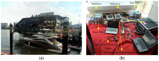
Figure 7.
Installation diagram of shipborne experiment; (a) overall view of shipborne experiment platform; (b) installation and layout of all equipment in the experiment platform.
The detailed information of data collected from the experiment is listed in Table 1. The sampling time was 10 ms.

Table 1.
Detailed information of data collected from the experiment.
In order to complete the precise alignment of the PHINS as quickly as possible during the experiment, approximately 20 min of maneuvering were carried out until the alignment of the PHINS was completed. After the alignment process was finished, static data were collected for 2 h. The fixed installation deviations between the testing IMUs and PHINS were determined by integrated alignment using the static data. The calculation results are shown in Table 2.
Table 2.
Installation deviation between testing IMUs and PHINS.
As shown in Table 2, installation deviation1 represents the installation deviation between the main IMU and PHINS-1 on the left side in Figure 7b, and installation deviation2 denotes the installation deviation between the sub-IMU and PHINS-2 on the right side in Figure 7b.
Figure 8 gives the navigation trajectory of the experimental platform.
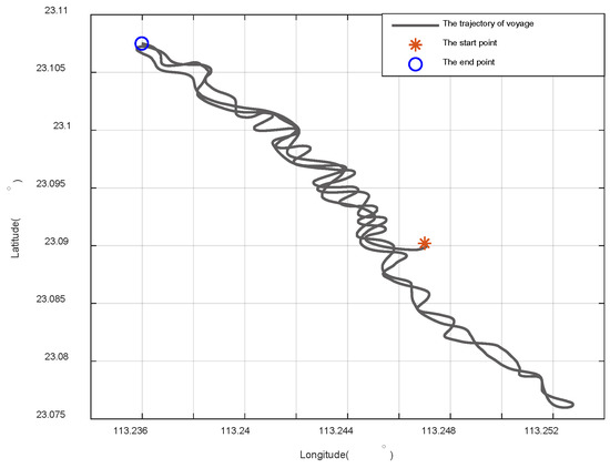
Figure 8.
The trajectory of the experimental platform.
Figure 9 gives the attitude error of the deck under different methods, and its RMSE is shown in Figure 10.
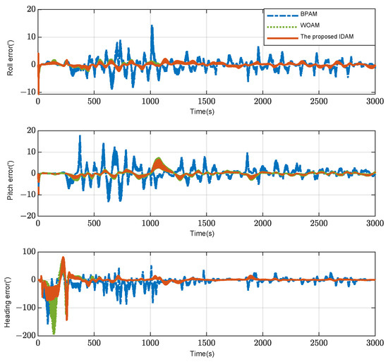
Figure 9.
Attitude measurement error.
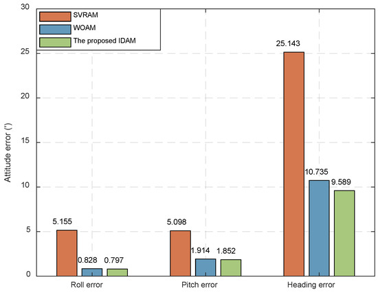
Figure 10.
RMSE of attitude measurement error.
From Figure 9, the following conclusions can be drawn: (1) Compared with the SVRAM method, the attitude errors of the WOAM and proposed IDAM methods were significantly reduced; (2) in terms of horizontal attitude error, the difference between the WOAM methods and the proposed IDAM methods was minimal; (3) in terms of heading error, the WOAM method had a large error, around 150 s, and the proposed IDAM method had better performance. Finally, the obtained conclusions are consistent with the simulation results.
It can be seen from Figure 10 that different methods have different attitude measurement performance. For the method based on SVRAM, the values of RMSE for roll, pitch, and heading are 5.155′, 5.098′, and 25.143′, respectively. For the method based on WOAM, the values of RMSE for roll, pitch, and heading are reduced to 0.828′, 1.914′, and 10.735′, respectively. Compared with SVRAM, the accuracy is improved by 83.94%, 62.46%, and 57.30%, respectively. Furthermore, the proposed IDAM achieves high-accuracy dynamic angle parameters, and the model prediction method further improves the estimation effect. Therefore, the estimated RMSE of roll, pitch, and heading angles are reduced to 0.797′, 1.852′, and 9.589′, which are 3.74%, 3.24%, and 10.68% better than WOAM, respectively, showing better attitude estimation performance and verifying the effectiveness of the proposed algorithm.
7. Conclusions
In order to address the difficulty of achieving accurate attitude information of typical deck areas, firstly, this paper carried out an online estimation of dynamic deformation model parameters by using the RVM algorithm to adapt to the complex changes in dynamic deformation of the deck. Secondly, an MPF-based dynamic attitude measurement method using maximum correlation entropy as the optimization criterion is proposed to deal with the influence of model truncation error and non-Gaussian noise. Finally, this paper designs a dynamic measurement model based on Rodrigues parameters in an inertial frame by integrating the application of the dynamic deformation model with adaptive parameters. Meanwhile, there is no restriction on the range of the misalignment angle and no need for sub-inertial navigation calculation. The experiment results and comparison analysis demonstrate that the proposed dynamic attitude inertial measurement method has higher estimation accuracy than the previous methods. Moreover, from an algorithm adaptability point of view, the proposed method significantly improves the navigation performance of inertial navigation systems in extreme cases.
In the future, we plan to test more types of algorithms and their combinations applied to this field and conduct the verification through shipborne experiments.
Author Contributions
Conceptualization: B.Z.; methodology: B.Z. and X.X.; validation: T.W.; software: T.W.; formal analysis: B.Z.; investigation: X.X.; resources: W.G.; writing—review and editing: B.Z. All authors have read and agreed to the published version of the manuscript.
Funding
This work was supported in part by the National Natural Science Foundation of China under Grant 52271315 and Grant 51909048, the China Postdoctoral Science Foundation under Grant 2019T120260, the Postdoctoral Foundation of Heilongjiang Province Government Grant LBH-TZ1015, and the Postdoctoral Foundation of Heilongjiang Province Government Grant LBH-Z22188.
Data Availability Statement
The data that support the findings of this study are available from the corresponding author upon reasonable request.
Acknowledgments
The authors of this paper would like to express their sincere gratitude to the editors and reviewers for their hard work.
Conflicts of Interest
The authors declare no conflict of interest.
References
- Wang, J.; Zhang, T.; Jin, B.; Zhu, Y.; Tong, J. Student’s t-Based Robust Kalman Filter for a SINS/USBL Integration Navigation Strategy. IEEE Sens. J. 2020, 20, 5540–5553. [Google Scholar] [CrossRef]
- Dai, H.; Lu, J.; Guo, W.; Wu, G.; Wu, X. IMU based deformation estimation about the deck of large ship. Optik 2016, 127, 3535–3540. [Google Scholar] [CrossRef]
- Wang, Y.; Sun, F.; Zhang, Y.; Liu, H.; Min, H. Central difference particle filter applied to transfer alignment for SINS on missiles. IEEE Trans. Aerosp. Electron. Syst. 2012, 48, 375–387. [Google Scholar] [CrossRef]
- Liu, X.; Xu, X.; Liu, Y.; Wang, L.H. A fast and high-accuracy transfer alignment method between M/S INS for ship based on iterative calculation. Measurement 2014, 51, 297–309. [Google Scholar] [CrossRef]
- Yang, G.; Wang, Y.; Yang, S. Assessment approach for calculating transfer alignment accuracy of SINS on moving base. Measurement 2014, 52, 55–63. [Google Scholar] [CrossRef]
- Peng, Y.; Zhang, A.; Ming, F.; Wang, S. A meshfree framework for the numerical simulation of elasto-plasticity deformation of ship structure. Ocean Eng. 2019, 192, 106507. [Google Scholar] [CrossRef]
- Seo, C.; Jeong, B.; Kim, J.; Song, M.; Noh, J.; Lee, J. Determining the influence of ship hull deformations caused by draught change on shaft alignment application using FE analysis. Ocean Eng. 2020, 210, 107488. [Google Scholar] [CrossRef]
- Xu, B.; Duan, T.; Wang, Y. An inertial measurement method of ship deformation basesd on IMM filtering. Optik 2017, 140, 601–609. [Google Scholar] [CrossRef]
- Wu, W.; Qin, S.; Chen, S. Coupling influence of ship dynamic flexure on high accuracy transfer alignment. Int. J. Model. Identif. Control 2013, 19, 224–234. [Google Scholar] [CrossRef]
- Zheng, J.; Yan, D.; Yan, M.; Yi, Y.; Zhao, Y. An unscented kalman filter online identification approach for a nonlinear ship motion model using a self-navigation test. Machines 2022, 10, 312. [Google Scholar] [CrossRef]
- Wu, W.; Chen, S.; Qin, S. Online estimation of ship dynamic flexure model parameters for transfer alignment. Ocean Eng. 2012, 21, 1666–1678. [Google Scholar] [CrossRef]
- Yu, D.; Yang, G.; Xie, Z. Online Estimation of Ship Dynamic Flexure Model Parameters Based on Particle Swarm Optimization. Nav. Control. 2019, 18, 71–79. [Google Scholar]
- Zhu, M.; Hahn, A.; Wen, Y.; Sun, W. Optimized support vector regression algorithm-based modeling of ship dynamics. Appl. Ocean. Res. 2019, 90, 101842. [Google Scholar] [CrossRef]
- Wang, Y.; Zhang, Y.; Xu, D.; Miao, W. Improved whale optimization-based parameter identification algorithm for dynamic deformation of large ships. Ocean Eng. 2022, 245, 110392. [Google Scholar] [CrossRef]
- Wang, Y.; Zhang, Y.; Wang, K.; Wang, Z.; Chang, J.; Xu, D. Research on multi-model adaptive hull deformation measurement algorithm. In Proceedings of the 2020 IEEE/ION Position, Location and Navigation Symposium (PLANS), Portland, OR, USA, 20–23 April 2020; pp. 718–722. [Google Scholar]
- Ren, B.; Li, T.; Li, X. Research on Dynamic Inertial Estimation Technology for Deck Deformation of Large Ships. Sensors 2019, 19, 4167. [Google Scholar] [CrossRef] [PubMed]
- Zhang, G.; Tan, F.; Wu, Y. Ship Motion Attitude Prediction Based on an Adaptive Dynamic Particle Swarm Optimization Algorithm and Bidirectional LSTM Neural Network. IEEE Access 2020, 8, 90087–90098. [Google Scholar] [CrossRef]
- Xu, D.; Peng, X.; Zhang, G.; Hu, X. An Improved Inertial Matching Algorithm for Hull Deformation with Large Misalignment Angle. IEEE Access 2021, 9, 36634–36644. [Google Scholar] [CrossRef]
- Crassidis, J.; Markley, F. Predictive filtering for nonlinear systems. J. Guid. Control Dyn. 1997, 20, 566–572. [Google Scholar] [CrossRef]
- Chatzis, S.; Kosmopoulos, D.; Varvarigou, T. Robust Sequential Data Modeling Using an Outlier Tolerant Hidden Markov Model. IEEE Trans. Pattern Anal. Mach. Intell. 2009, 31, 1657–1669. [Google Scholar] [CrossRef]
- Winters-Hilt, S.; Jiang, Z. A Hidden Markov Model with Binned Duration Algorithm. IEEE Trans. Signal. Proces. 2010, 58, 948–952. [Google Scholar] [CrossRef]
- Mu, H.; Han, L.; Li, A. Application of Model Prediction Filter in Shipborne Weapons Initial Alignment. Ship Electron. Eng. 2021, 41, 47–50. [Google Scholar]
- Hu, G.; Ni, L.; Gao, B.; Zhu, X.; Wang, W.; Zhong, Y. Model Predictive Based Unscented Kalman Filter for Hypersonic Vehicle Navigation with INS/GNSS Integration. IEEE Access 2019, 8, 4814–4823. [Google Scholar] [CrossRef]
- Lu, J.; Xie, L.; Li, B. Applied quaternion optimization method in transfer alignment for airborne AHRS under large misalignment angle. IEEE Trans. Instrum. Meas. 2015, 65, 346–354. [Google Scholar] [CrossRef]
- Gong, X.; Fan, W.; Fang, J. An innovational transfer alignment method based on parameter identification UKF for airborne distributed POS. Measurement 2014, 58, 103–114. [Google Scholar] [CrossRef]
- Mochalov, A.; Kazantsev, A. Use of ring laser units for measurement of moving object deformations. Symmetry 2002, 4680, 85–92. [Google Scholar]
- Tipping, M. Sparse Bayesian learning and the relevance vector machine. J. Mach. Learn. Res. 2001, 1, 211–244. [Google Scholar]
Disclaimer/Publisher’s Note: The statements, opinions and data contained in all publications are solely those of the individual author(s) and contributor(s) and not of MDPI and/or the editor(s). MDPI and/or the editor(s) disclaim responsibility for any injury to people or property resulting from any ideas, methods, instructions or products referred to in the content. |
© 2024 by the authors. Licensee MDPI, Basel, Switzerland. This article is an open access article distributed under the terms and conditions of the Creative Commons Attribution (CC BY) license (https://creativecommons.org/licenses/by/4.0/).