
Quantum-Dot CA-Based Fredkin Gate and Conservative D-Latch for Reliability-Based Information Transmission on Reversible Computing

Abstract
1. Introduction
- FRGs, which are universal reversible gates, are designed using QCA.
- Conservative reversible D-latches using the proposed FRGs are designed.
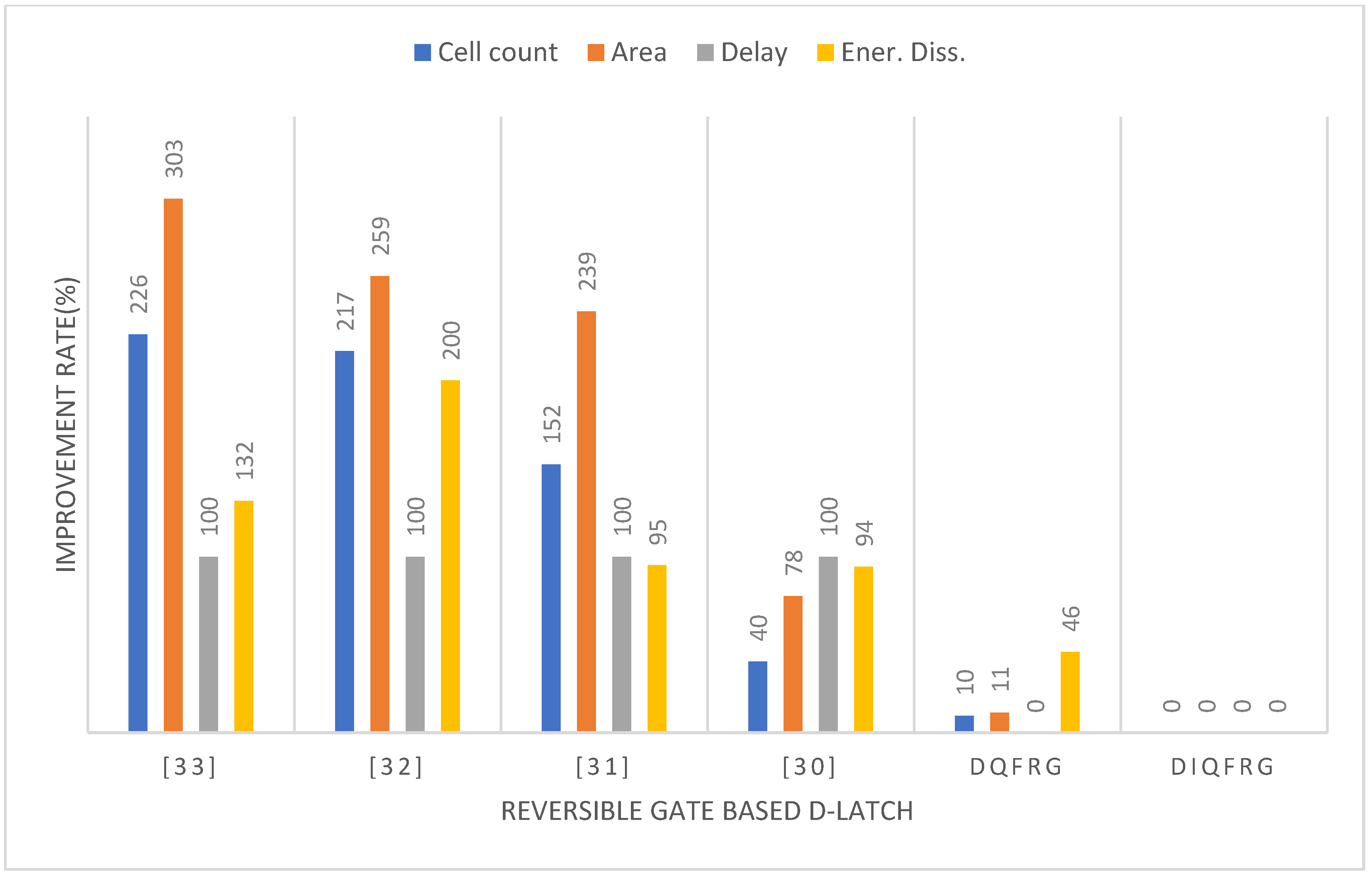
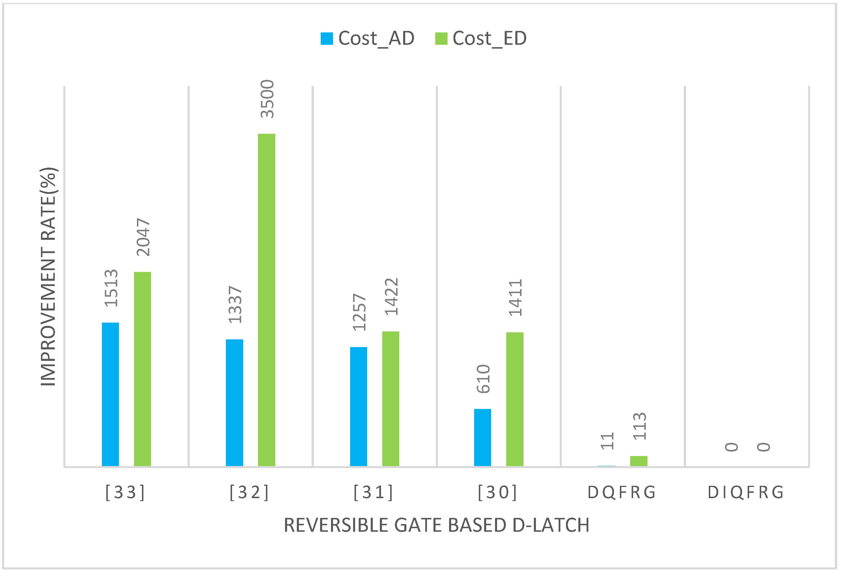
- The proposed study analyzes the performance of cell count, area, delay, and energy dissipation required for implementation, calculates two representative standard design costs, and compares them with existing studies.
- The proposed QCA-based circuits showed significant improvement in most performances and design costs compared to existing excellent circuits.
2. Related Works
2.1. Fredkin Gate
2.2. Basics of QCA
2.3. QCA-Based Multiplexer and D-Latch
3. Proposed QCA-Based Fredkin Gate
4. Performance Analysis and Comparison
5. Conclusions
Funding
Data Availability Statement
Conflicts of Interest
References
- Bennett, C.H. Logical reversibility of computation. IBM J. Res. Dev. 1973, 17, 525–532. [Google Scholar] [CrossRef]
- Landauer, R. Irreversibility and heat generation in the computing process. IBM J. Res. Dev. 1961, 5, 183–191. [Google Scholar] [CrossRef]
- Feynman, R. Quantum Mechanical Computers. Opt. News 1985, 11, 11–20. [Google Scholar] [CrossRef]
- Fredkin, E.; Toffoli, T. Conservative Logic. Int. J. Theor. Phys. 1982, 21, 219–253. [Google Scholar] [CrossRef]
- Bruce, J.W.; Thornton, M.A.; Shivakumaraiah, L.; Kokate, P.S.; Li, X. Efficient adder circuits based on a conservative reversible logic gate. In Proceedings of the IEEE Computer Society Annual Symposium on VLSI, IEEE Computer Society, Pittsburgh, PA, USA, 25–26 April 2002. [Google Scholar]
- Lent, C.S.; Tougaw, P.D.; Porod, W. Quantum cellular automata: The physics of computing with arrays of quantum dot molecules. Proc. Workshop Phys. Comput. 1994, 17, 5–13. [Google Scholar]
- Tougaw, P.D.; Lent, C.S. Logical devices implemented using quantum cellular automata. J. Appl. Phys. 1993, 75, 1818–1825. [Google Scholar] [CrossRef]
- Tougaw, P.D.; Lent, C.S. Dynamic behavior of quantum cellular automata. J. Appl. Phys. 1996, 80, 4722–4736. [Google Scholar] [CrossRef]
- Srivastava, S.; Sarkar, S.; Bhanja, S. Power dissipation bounds and models for quantum-dot cellular automata circuits. In Proceedings of the 2006 Sixth IEEE Conference on Nanotechnology, Cincinnati, OH, USA, 17–20 July 2006; Volume 1, pp. 375–378. [Google Scholar]
- Srivastava, S.; Sarkar, S.; Bhanja, S. Estimation of upper bound of power dissipation in QCA circuits. IEEE Trans. Nanotechnol. 2009, 8, 116–127. [Google Scholar] [CrossRef]
- Patidar, M.; Gupta, N. An ultra-efficient design and optimized energy dissipation of reversible computing circuits in QCA technology using zone partitioning method. Int. J. Inf. Technol. 2021, 14, 1483–1493. [Google Scholar] [CrossRef]
- Mukherjee, C.; Panda, S.; Mukhopadhyay, A.K.; Maji, B. Utilization of LTEx Feynman Gate in Designing the QCA Based Reversible Binary to Gray and Gray to Binary Code Converters. Micro Nanosyst. 2020, 12, 187–200. [Google Scholar] [CrossRef]
- Bahar, A.N.; Ahmad, F.; Nahid, N.M.; Hassan, K.; Al Shafi, A.; Ahmed, K. An optimal design of conservative effi-cient reversible parity logic circuits using QCA. Int. J. Inf. Technol. 2018, 11, 785–794. [Google Scholar]
- Debnath, B.; Das, J.C.; De, D.; Ghaemi, F.; Ahmadian, A.; Senu, N. Reversible Palm Vein Authenti-cator Design with Quantum Dot Cellular Automata for Information Security in Nanocommunication Network. IEEE Access 2020, 8, 174821–174832. [Google Scholar] [CrossRef]
- Vahabi, M.; Rahimi, E.; Lyakhov, P.; Bahar, A.N.; Wahid, K.A.; Otsuki, A. Novel Quantum-Dot Cellular Automata-Based Gate Designs for Efficient Reversible Computing. Sustainability 2023, 15, 2265. [Google Scholar] [CrossRef]
- Safoev, N.; Abdukhalil, G.; Abdisalomovich, K.A. QCA based Priority Encoder using Toffoli gate. In Proceedings of the 2020 IEEE 14th International Conference on Application of Information and Communication Technologies (AICT), Tashkent, Uzbekistan, 7–9 October 2020; pp. 1–4. [Google Scholar]
- Iqbal, J.; Banday, M.T. Applications of Toffoli Gate for designing the classical gates using quantum-dot cellular automata. Int. J. Recent. Sci. Res. 2015, 6, 7764–7769. [Google Scholar]
- Patidar, M.; Arul Kumar, D.; William, P.; Loganathan, G.B.; Mohathasim Billah, A.; Manikandan, G. Optimized design and investigation of novel reversible toffoli and peres gates using QCA techniques. Meas. Sens. 2024, 32, 101036. [Google Scholar] [CrossRef]
- Das, J.C.; De, D. Novel low power reversible binary incrementer design using quantum-dot cellular automata. Microprocess. Microsyst. 2016, 42, 10–23. [Google Scholar] [CrossRef]
- Reshi, J.I.; Banday, M.T. Realization of Peres gate as universal structure using quantum Dot cellular automata. J. Nanosci. Technol. 2016, 2, 115–118. [Google Scholar]
- Thapliyal, H.; Ranganathan, N. Conservative QCA Gate (CQCA) for Designing Concurrently Testable Molecular QCA Circuits. In Proceedings of the 2009 22nd International Conference on VLSI Design, New Delhi, India, 5–9 January 2009; pp. 511–516. [Google Scholar]
- Bhoi, B.K.; Misra, N.K.; Pradhan, M. Analysis on Fault Mapping of Reversible Gates with Ex-tended Hardware Description Language for Quantum Dot Cellular Automata Approach. Sens. Lett. 2019, 17, 371–378. [Google Scholar] [CrossRef]
- Das, J.C.; De, D. Computational fidelity in reversible quantum-dot cellular automata channel routing under thermal randomness. Nano Commun. Netw. 2018, 18, 17–26. [Google Scholar] [CrossRef]
- Kundu, A.; Das, J.C.; De, D. RSCV: Reversible Select, cross and variation architecture in quantum-dot cellular automata. IET Quantum Commun. 2022, 3, 139–149. [Google Scholar] [CrossRef]
- Kianpour, M.; Sabbaghi-Nadooshan, R. Novel 8-bit reversible full adder/subtractor using a QCA reversible gate. J. Comput. Electron. 2017, 16, 459–472. [Google Scholar] [CrossRef]
- Sasamal, T.N.; Singh, A.K.; Ghanekar, U. Toward Efficient Design of Reversible Logic Gates in Quantum-Dot Cellular Automata with Power Dissipation Analysis. Int. J. Theor. Phys. 2017, 57, 1167–1185. [Google Scholar] [CrossRef]
- Pathak, N.; Misra, N.K.; Bhoi, B.K.; Kumar, S. Reversible Gate Mapping into QCA Explicit Cells Packed with Single Layer. IOP Conf. Ser. Mater. Sci. Eng. 2021, 1119, 012004. [Google Scholar] [CrossRef]
- Roy, A.; Singh, A.D.; Saha, A.; Saha, S.; Gupta, V.; Qingyi, Z.; Bhattacharya, S.; Bhattacharjee, S. A Novel Design of Reversible Gate using Quantum-Dot Cellular Automata (QCA). In Proceedings of the 2020 IEEE 1st International Conference for Convergence in Engineering (ICCE), Kolkata, India, 5–6 September 2020; pp. 110–115. [Google Scholar]
- Abutaleb, M.M. Robust and efficient QCA cell-based nanostructures of elementary reversible logic gates. J. Supercomput. 2018, 74, 6258–6274. [Google Scholar] [CrossRef]
- Naz, S.F.; Ahmed, S.; Sharma, S.; Ahmad, F.; Ajitha, D. Fredkin gate based energy efficient reversible D flip flop design in quantum dot cellular automata. Mater. Today Proc. 2021, 46, 5248–5255. [Google Scholar] [CrossRef]
- Chabi, A.M.; Roohi, A.; Khademolhosseini, H.; Sheikhfaal, S.; Angizi, S.; Navi, K.; DeMara, R.F. Towards ultra-efficient QCA reversible circuits. Microprocess. Microsyst. 2017, 49, 127–138. [Google Scholar] [CrossRef]
- Bhoi, B.; Misra, N.K.; Pradhan, M.; Chong Tan, S. Design and evaluation of an efficient parity-preserving reversible QCA gate with online testability. Cogent Eng. 2017, 4, 1416888. [Google Scholar] [CrossRef]
- Mohammadi, Z.; Navi, K.; Sabbaghi-Nadooshan, R. Design of testable reversible latches by using a novel efficient implementation of Fredkin gate. Int. J. Electron. 2020, 107, 859–878. [Google Scholar] [CrossRef]
- Safoev, N.; Jeon, J.C. A novel controllable inverter and adder/subtractor in quantum-dot cellular automata using cell interaction based XOR gate. Microelectron. Eng. 2020, 222, 111197. [Google Scholar] [CrossRef]
- Azimi, S.; Angizi, S.; Moaiyeri, M.H. Efficient and Robust SRAM Cell Design Based on Quantum-Dot Cellular Automata. ECS Solid State Sci. Technol. 2018, 7, 38–45. [Google Scholar] [CrossRef]
- Sasamal, T.N.; Singh, A.K.; Ghanekar, U. Design and Implementation of QCA D-Flip-Flops and RAM Cell Using Majority Gates. J. Circuits Syst. Comput. 2019, 8, 1950079. [Google Scholar] [CrossRef]
- Jeon, J.C. Designing nanotechnology QCA–multiplexer using majority function-based NAND for quantum computing. J. Supercomput. 2021, 77, 1562–1578. [Google Scholar] [CrossRef]
- Rezai, A.; Aliakbari, D.; Karimi, A. Novel multiplexer circuit design in quantum-dot cellular automata technology. Nano Commun. Netw. 2023, 35, 100435. [Google Scholar] [CrossRef]
- Jeon, J.C. Low-complexity QCA universal shift register design using multiplexer and D flip-flop based on electronic correlations. J. Supercomput. 2019, 76, 6438–6452. [Google Scholar] [CrossRef]
- Almatrood, A.; George, A.K.; Singh, H. Low-Power Multiplexer Structures Targeting Efficient QCA Nanotechnology Circuit Designs. Electronics 2021, 10, 1885. [Google Scholar] [CrossRef]
- Ahmadpour, S.S.; Mohammad, M.; Heikalabad, S.R. Efficient designs of quantum-dot cellular automata multiplexer and RAM with physical proof along with power analysis. J. Supercomput. 2022, 78, 1672–1695. [Google Scholar] [CrossRef]
- Vahabi, M.; Rahimi, E.; Lyakhov, P.; Otsuki, A. A novel QCA circuit-switched network with power dissipation analysis for nano communication applications. Nano Commun. Netw. 2023, 35, 100438. [Google Scholar] [CrossRef]
- Jeon, J.C. Multi-Layer QCA Shift Registers and Wiring Structure for LFSR in Stream Cipher with Low Energy Dissipation in Quantum Nanotechnology. Electronics 2023, 12, 4093. [Google Scholar] [CrossRef]
- Alghosi, A.; Gholami, M.; Ghoreishi, S.S.; Adarang, H. Novel multiplexer, latch, and shift register in QCA nanotechnology for high-speed computing systems. Eur. Phys. J. Plus 2024, 139, 266. [Google Scholar] [CrossRef]
- Senthilnathan, S.; Kumaravel, S. Power-efficient implementation of pseudo-random number generator using quantum dot cellular automata-based D Flip Flop. Comput. Electr. Eng. 2020, 85, 106658. [Google Scholar] [CrossRef]
- Seo, D.-K.; Jeon, J.-C. QCA-Based Secure RAM Cell Structure Using Logic Transformation and Cell Interaction with Signal Reliability and Energy Dissipation in Quantum Computing. Appl. Sci. 2023, 13, 9998. [Google Scholar] [CrossRef]
- Walus, K.; Dysart, T.J.; Jullien, G.A.; Budiman, R.A. QCADesigner: A rapid design and simulation tool for quantum-dot cellular automata. IEEE Trans. Nanotechnol. 2004, 3, 26–31. [Google Scholar] [CrossRef]
- Qcadesigner-e. Available online: https://github.com/FSillT/QCADesigner-E (accessed on 21 May 2024).
- Liu, W.; Lu, L.; O’Neill, M.; Swartzlander, E.E. A First Step toward Cost Functions for Quantum-Dot Cellular Automata Designs. IEEE Trans. Nanotechnol. 2014, 12, 476–487. [Google Scholar]


| Inputs | Outputs | ||||
|---|---|---|---|---|---|
| A | B | C | P = A | Q = A′B + AC | R = AB + A′C |
| 0 | 0 | 0 | 0 | 0 | 0 |
| 0 | 0 | 1 | 0 | 0 | 1 |
| 0 | 1 | 0 | 0 | 1 | 0 |
| 0 | 1 | 1 | 0 | 1 | 1 |
| 1 | 0 | 0 | 1 | 0 | 0 |
| 1 | 0 | 1 | 1 | 1 | 0 |
| 1 | 1 | 0 | 1 | 0 | 1 |
| 1 | 1 | 1 | 1 | 1 | 1 |
| Inputs | Output | ||
|---|---|---|---|
| CLK | D | Qn | Qn+1 |
| 0 | x | 0 | 0 |
| 0 | x | 1 | 1 |
| 1 | 0 | x | 0 |
| 1 | 1 | x | 1 |
| QCADesigner 2.0.3 | QCADesigner-E | |
|---|---|---|
| Parameters | Bistable Approximation | Coherence Vector with Energy |
| Cell size (nm) | 18 | 18 |
| Dot diameter (nm) | 5 | 5 |
| Cell separation (nm) | 2 | 2 |
| Layer separation (nm) | 11.5 | 11.5 |
| Clock high (J) | 9.8 × 10⁻²² | 9.8 × 10⁻²² |
| Clock low (J) | 3.8 × 10⁻²³ | 3.8 × 10⁻²³ |
| Clock shift | 0 | 0 |
| Clock amplitude factor | 2.0 | 2.0 |
| Relative permittivity | 12.9 | 12.9 |
| Radius of effect (nm) | 65 | 80 |
| Number of samples | 12,800 | - |
| Convergence tolerance | 1.0 × 10⁻³ | - |
| Maximum iterations per sample | 100 | - |
| Temperature (K) | - | 1 |
| Relaxation time (s) | - | 1.0 × 10⁻¹⁵ |
| Clock slope (s) | - | 1.0 × 10⁻¹² |
| Time step (s) | - | 1.0 × 10⁻¹⁶ |
| Clock/input period (s) | - | 4.0 × 10⁻¹² |
| FRG Circuit | Cell Count | Area (µm2) | Delay (Clock Phase) | Ener. Diss. (10−2 eV) | ||
|---|---|---|---|---|---|---|
| [22] | 108 | 0.094 | 6 | 3.31 | 3.383 | 394.4 |
| [23] | 109 | 0.150 | 4 | 3.71 | 2.407 | 220.2 |
| [24] | 83 | 0.096 | 3 | 4.33 | 0.861 | 168.7 |
| [25] | 94 | 0.091 | 3 | 3.95 | 0.820 | 140.4 |
| [26] | 68 | 0.065 | 3 | 2.75 | 0.585 | 68.1 |
| [27] | 68 | 0.064 | 3 | 2.34 | 0.578 | 49.3 |
| [28] | 57 | 0.048 | 3 | 4.02 | 0.431 | 145.4 |
| [29] | 42 | 0.042 | 3 | 1.23 | 0.381 | 13.6 |
| [30] | 48 | 0.048 | 4 | 3.67 | 0.760 | 215.5 |
| QFRG | 33 | 0.025 | 2 | 1.96 | 0.098 | 15.4 |
| IQFRG | 30 | 0.022 | 2 | 1.29 | 0.087 | 6.7 |
Disclaimer/Publisher’s Note: The statements, opinions and data contained in all publications are solely those of the individual author(s) and contributor(s) and not of MDPI and/or the editor(s). MDPI and/or the editor(s) disclaim responsibility for any injury to people or property resulting from any ideas, methods, instructions or products referred to in the content. |
© 2024 by the author. Licensee MDPI, Basel, Switzerland. This article is an open access article distributed under the terms and conditions of the Creative Commons Attribution (CC BY) license (https://creativecommons.org/licenses/by/4.0/).
Share and Cite
Jeon, J.-C. Quantum-Dot CA-Based Fredkin Gate and Conservative D-Latch for Reliability-Based Information Transmission on Reversible Computing. Electronics 2024, 13, 2872. https://doi.org/10.3390/electronics13142872
Jeon J-C. Quantum-Dot CA-Based Fredkin Gate and Conservative D-Latch for Reliability-Based Information Transmission on Reversible Computing. Electronics. 2024; 13(14):2872. https://doi.org/10.3390/electronics13142872
Chicago/Turabian StyleJeon, Jun-Cheol. 2024. "Quantum-Dot CA-Based Fredkin Gate and Conservative D-Latch for Reliability-Based Information Transmission on Reversible Computing" Electronics 13, no. 14: 2872. https://doi.org/10.3390/electronics13142872
APA StyleJeon, J.-C. (2024). Quantum-Dot CA-Based Fredkin Gate and Conservative D-Latch for Reliability-Based Information Transmission on Reversible Computing. Electronics, 13(14), 2872. https://doi.org/10.3390/electronics13142872