Abstract
In response to the problems of impedance variation and rich background harmonics in the weak grid environment of traditional LCL grid-connected inverters, which cause distortion of the grid-connected current and reduce the stability of the entire grid-connected system, this paper proposes a passive fuzzy-active disturbance rejection control strategy. Firstly, passivity-based control (PBC) is introduced into the grid-connected inverter system to ensure the global stability of the entire system. Secondly, in order to solve the problem of difficult selection of inverter-side current, active disturbance rejection control (ADRC) is used to directly track the grid-connected current, avoiding the tracking error of AC signal and suppressing the interference of background harmonics of grid voltage. The combination of fuzzy control and ADRC simplifies the system parameter tuning process, and the FUZZY-ADRC grid-connected current outer loop and PBC inductance current inner loop are combined to form a multi-loop control system. Finally, simulation comparison verifies that the proposed control strategy can effectively suppress the harmonics of grid-connected current, improve the quality of grid-connected current, and enhance the stability of the entire grid-connected system in a weak grid environment.
1. Introduction
In recent years, with the increasing depletion of fossil energy and in order to ensure the achievement of China’s carbon peak and carbon neutral goals, new green renewable energy sources such as photovoltaic, wind power, etc. have begun to be developed on a large scale. However, most of the abundant natural energy sources are distributed in remote areas, and due to the long-distance transmission which makes the line impedance increase and the multi-stage loop transformer, the power generation side will show weak grid characteristics with the grid side, i.e., grid Performance as resistive inductive, and the grid voltage contains rich background harmonics, which makes the grid-connected current distorted and the stability of the whole grid-connected system is reduced [1,2,3,4,5]. Low-pass passive filters are commonly utilized to enhance power quality and eliminate harmonics in grid-connected converters. The LCL-type filter, which boasts a smaller inductance, lower cost, and higher rate of harmonic elimination, is preferred over the L-type filter. As a result, it has become widely adopted in grid-connected inverters [6]. Currently, the precise tracking of grid-connected current and the realization of stable control of LCL grid-connected inverters have become the focus of research by domestic and foreign scholars.
At present, there are many control methods for grid-connected inverters, including proportional integral (PI) control, proportional resonant (PR) control, repetitive control, and grid voltage feedforward control. PI control is widely used in the industrial field because of its simple control structure and easy operation. However, it cannot achieve static error tracking for non-direct currents such as sinusoidal signals, and it is difficult to be applied in single-phase grid-connected systems [7]. PR control can completely eliminate the steady-state error of sine quantity [8,9]. However, under the condition of a weak power grid, the operating frequency of the power grid is prone to fluctuation and is affected by the harmonics of the power grid, so that the gain of the controller at the fundamental frequency is greatly reduced, which can no longer meet the accurate tracking requirements of the power grid current. Repetitive control can achieve no static error tracking of the control quantity, and has a good inhibitory effect on the periodic grid voltage background harmonics, but its dynamic performance is poor and generally not used alone [10]. The feedforward control of the grid voltage is different from the first two control methods to increase the loop gain at the harmonic frequency to suppress the harmonic component in the grid-connected current. Instead, the coupling term is processed in a voltage feed-forward manner to overcome the interference of voltage harmonics on the grid-connected current and improve the quality of the grid-connected current. However, in the weak grid, the change of the grid impedance will lead to a significant decrease in the system phase margin, which makes the model-based feed-forward solution blocked in practical applications, thus affecting the robustness of the entire grid-connected system [11]. As in [12], a feedforward control loop is designed to eliminate the negative effects of PLL and external power control loop on low-frequency stability. There are also some composite control methods that combine them. For example, in Reference [13] repetitive control and PI control are combined to suppress grid harmonics and improve the dynamic response capability of the inverter, but its PI parameters are difficult to adjust, and the influence of grid impedance under a weak grid is not considered. Reference [14] combines repetitive control with multi-resonant feedforward control, which has good adaptability to a weak grid environment. However, when the harmonic frequency of the system is higher than the cut-off frequency of the controller, it may cause system instability. In Reference [15], the combination of repetitive control and PR control requires multiple controllers to suppress each harmonic, resulting in too complicated an algorithm and coupling between controllers.
These control algorithms have their own advantages and scope of application. The common disadvantage is that they do not take into account the energy dissipation characteristics of the control object, while passivity-based control (PBC) considers the energy dissipation characteristics and is designed to maintain the global asymptotic stability of the system, and has strong robustness to system parameter changes [16,17]. For example, the frequency domain passive theory is considered in Reference [18]. By extracting the eigenvalue information from the impedance frequency response, the traditional eigenvalue-based and impedance-based stability analysis methods are improved. Since the single-phase LCL grid-connected inverter under a weak grid is a nonlinear system and the system parameters are variable under a weak grid, aiming at the above problems, this paper first establishes a passivity-based controller based on the Euler Lagrange (EL) model, which ensures the global stability of the whole system and improves the adaptability of the grid-connected system under weak grid conditions. Subsequently, a control strategy combining active disturbance rejection control (ADRC) and PBC is adopted to achieve static error-free tracking and harmonic suppression of grid-connected current. The parameters of ADRC are adjusted in real-time by adding fuzzy control, and detailed fuzzy control rules are given. Finally, the system model is built in MATLAB/Simulink, and the correctness and effectiveness of the proposed control strategy are verified by simulation experiments.
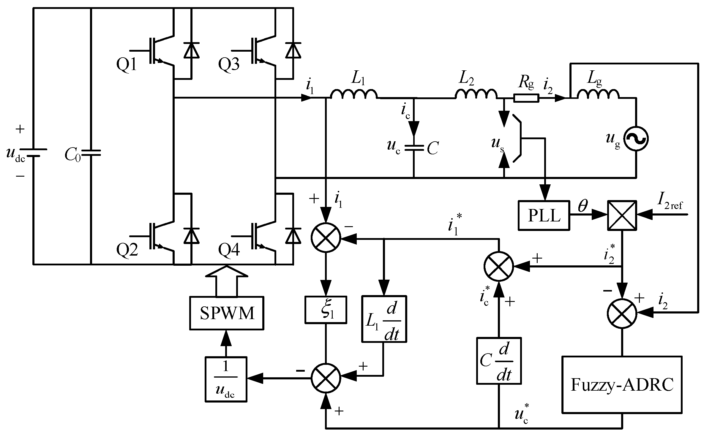
2. EL Mathematical Model of Single-Phase LCL Inverter in Weak Grid
The equivalent model of a single-phase LCL grid-connected inverter system in the weak grid is shown in Figure 1. In the figure, udc is the DC voltage, which can be regarded as a constant. L1, L2 and C are the inductance and capacitance of the LCL filter, respectively. Lg and Rg are the internal inductance and internal resistance of the grid, uc and ug are the filter capacitor voltage and the ideal grid voltage, and us is the sum of the voltage drop of ug voltage and its impedance Lg and Rg. i1 is the inverter side current, ic is the filter capacitor current, i2 is the grid current, Q1, Q2, Q3, Q4 are the four power-switching devices of the full-bridge inverters.
Figure 1.
Equivalent model of single-phase LCL grid-connected inverter in the weak grid.
According to Figure 1, based on Kirchhoff′s law, the state variables of the control system are selected as: inverter side current i1, capacitor voltage uc, and grid-connected current i2. The state equation of a single-phase LCL grid-connected inverter under a weak grid can be obtained as follows:
In the above formula, uA = 2d(t) − 1, where uA is the switching function, and d(t) represents the duty cycle of the switching devices Q1 and Q4.
For the weak grid-connected operating environment, the EL form of the single-phase grid-connected inverter can be deduced from Equation (2) as
In the formula, Mp is a positive definite diagonal matrix and JP is an antisymmetric matrix, which reflects the energy interconnection relationship within the system; Rp is a non-negative definite matrix, reflecting the energy dissipation of the system; Up is the control input matrix, which reflects the interaction between the system and the external energy. For the above system, the state variables can be defined as x1 = i1, x2 = uc, x3 = i2. The specific expressions of each matrix are:
The error energy storage function of a single-phase LCL grid-connected inverter system under a weak grid is defined as follows:
In the definition, xe is the system error state variable, that is, xe = xx*, x* is the given reference quantity. Bring it into Equation (2) can obtain:
In order to make the state variable of the system follow the given reference value and make the state variable xe of the system error zero, there is
Using Equation (10) we obtain:
It can be obtained from Equation (11) that the time for the energy function H to converge to 0 is determined by its inherent damping. Then, the strategy of adding damping can significantly accelerate its convergence to the equilibrium point and shorten the time for its reduction to zero. The form of injected damping is
where ξ1 is the damping factor, and ξ1 is greater than 0. Then Equation (9) can be changed to
Select the new control law as
Then when , there is
It can be seen from Equation (15) that injecting damping into the system can significantly affect the speed at which the system converges to zero.
Based on the above equations, the control equation of the passivity-based controller can be deduced as
It can be seen from Equation (16) that the control law is not directly related to the grid impedance. Therefore, the passivity-based controller designed in this paper is suitable for single-phase grid-connected inverters, and can be applied indiscriminately in the strong grid and weak grid with variable grid impedance.
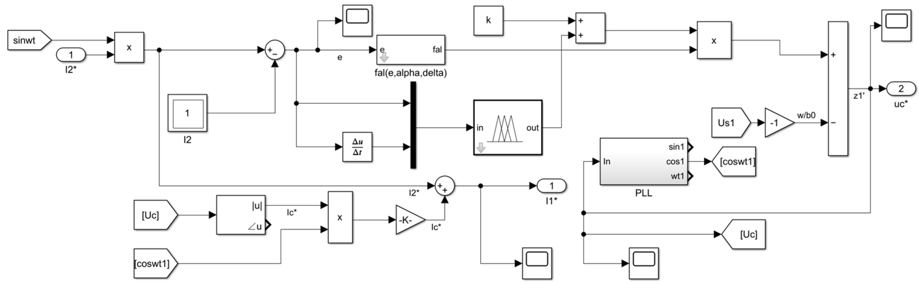
3. Design of Fuzzy-Active Disturbance Rejection Control
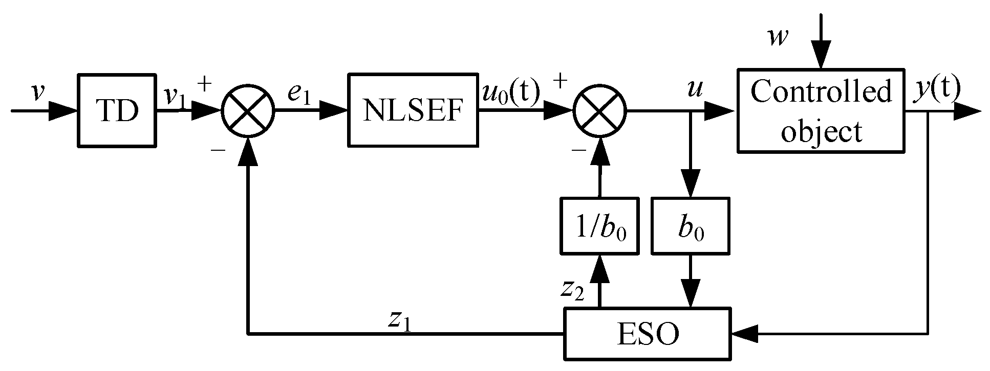
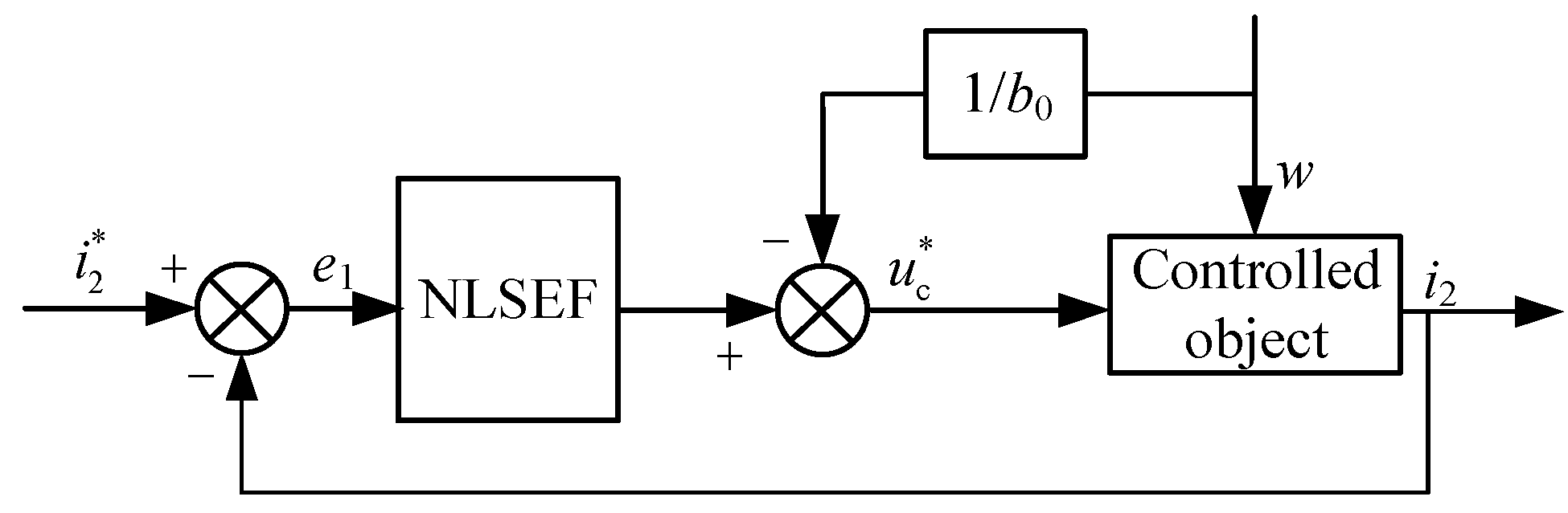
3.1. Active Disturbance Rejection Controller
When the inverter is connected to the grid, the current controller is usually used to ensure the accurate tracking of the grid current. However, when the control method of Equation (16) is adopted, although the global stability of the whole system is guaranteed under the disturbance away from the working point, there is no direct tracking of the grid-connected current, but the tracking of the inverter-side current i1 is used to indirectly complete the output current control. Because the calculation process of i1r includes the first and second derivatives of the grid voltage, and it is affected by the change of the system model parameters, it is very difficult to accurately obtain i1r. At the same time, the rich background harmonics in the grid voltage will also interfere with its accurate trackings, such as causing amplitude error and phase lag, which leads to the deterioration of the entire system performance. Therefore, it is considered to use active disturbance rejection control to generate reference i1r and realize zero steady-state error and harmonic suppression of sinusoidal current control.
Active disturbance rejection controller generally includes tracking differentiator (TD), extended state observer (ESO), and nonlinear state error feedback control law (NLSEF) [19,20,21], and its principle structure is shown in Figure 2. The function of the tracking differentiator is to arrange the transition process and give the differential signal of this process; the extended state observer is to estimate the state and disturbance of the system; the nonlinear state error feedback control law compensates the obtained disturbance component [22,23]. ADRC does not require accurate model parameters of the system. The uncertainty of the system’s own model parameters and the external disturbances such as low-frequency voltage harmonics in the system can be regarded as disturbances of the entire system, and can be estimated and compensated by ESO and NLSEF links. Therefore, it has a certain resonance suppression ability, and has strong robustness and automatic adjustment ability [24]. The first-order ADRC control system can be expressed as-
Figure 2.
ADRC principle structure diagram.
In the above formula, and are the adjustable parameters of the controller, is the speed factor, , and is the tracking factor, and k are the output error correction gain and the regulator gain respectively, is the compensation factor, , and is the filter factor, Z1 represents the observation value of the output, Z2 represents the observation value of the disturbance, w is the total disturbance of the system, v is the input signal, y(t) is the output signal. It can be seen from the above formula that there are more than ten parameters to be tuned in the active disturbance rejection controller. Too many parameters make it difficult to tune and difficult to apply in practical engineering problems. The following will simplify the design of the whole system.
From the equivalent model of a grid-connected inverter in Figure 1, it can be obtained that
By further simplifying Equation (21), the canonical form of auto disturbance rejection controller can be obtained as
where: ; ; .
b0 is the estimated value of the system gain, which is related to the filter inductance L2 and the grid inductance Lg. w is the total disturbance of the whole current closed-loop control system, including internal disturbances such as filter inductance L2, grid impedance Lg and Rg, and external disturbances such as grid current i2 and grid voltage ug.
Since it is a first-order system, the first-order ADRC controller mentioned above will be used to replace the traditional PR controller. The ESO in the general first-order ADRC controller does not output the differential signal of the control object, and it is convenient to directly measure the grid current. Therefore, the TD and ESO links can be eliminated. In the case of ensuring the system control performance, the system structure can be simplified by using only the nonlinear control function NLSEF. The input is the error e1 between the actual value and the reference value of the grid current, and the output capacitor voltage reference value uc* after the active disturbance rejection controller. The error feedback control law is
Through the improved auto disturbance rejection controller, the control parameters will only have parameters such as to simplify the subsequent tuning process. The simplified auto disturbance rejection control block diagram of the system is shown in Figure 3.
Figure 3.
Simplified active disturbance rejection control block diagram.
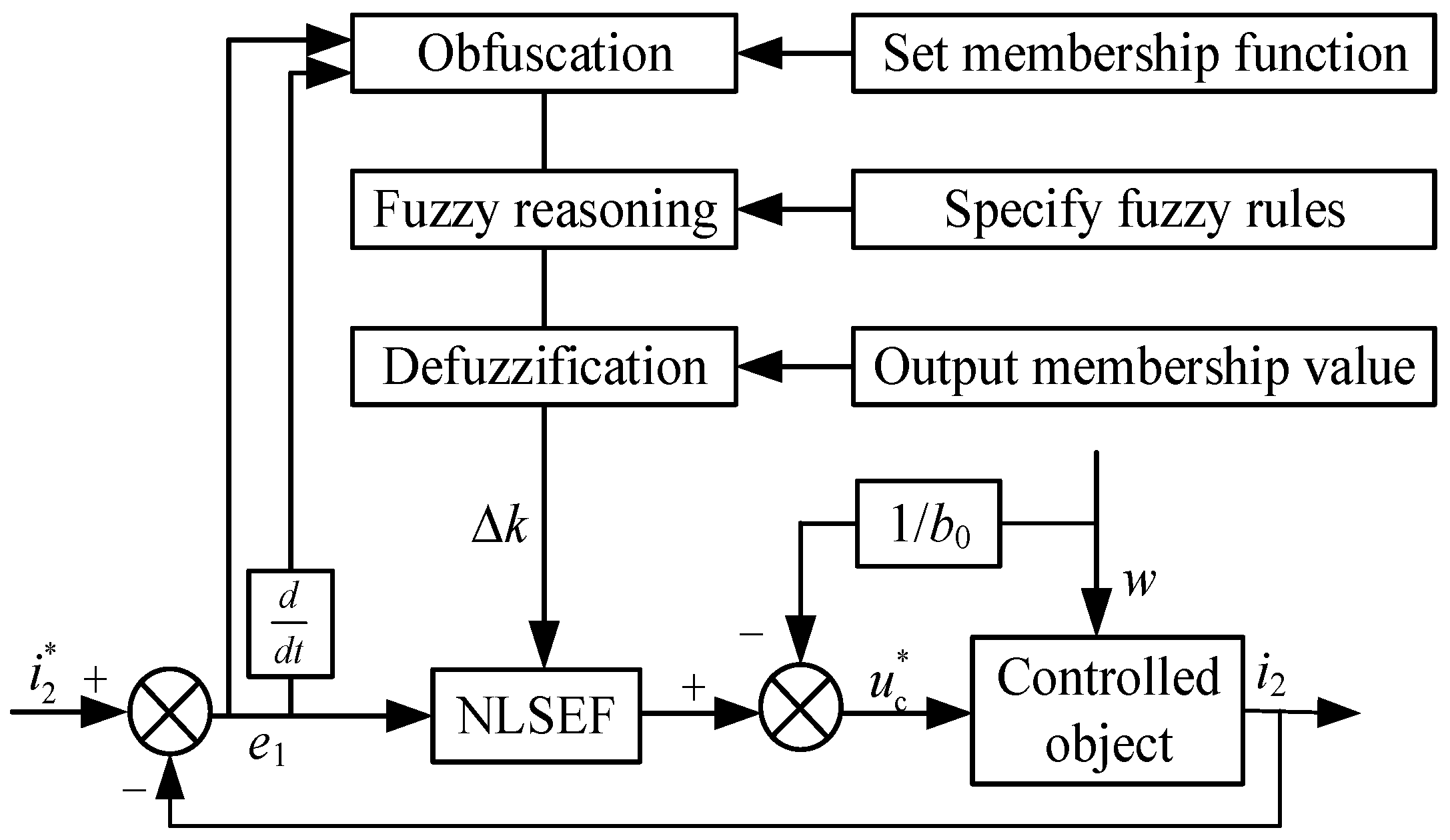
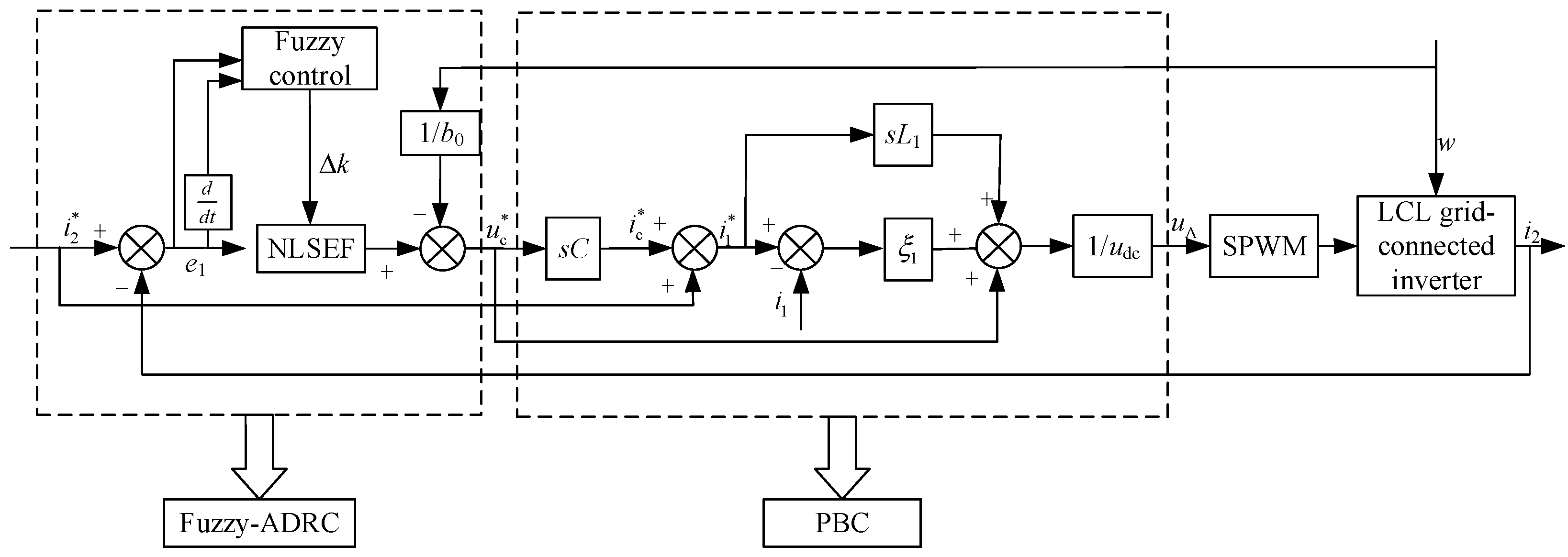
3.2. B. Fuzzy-Active Disturbance Rejection Controller (FUZZY-ADRC) Design
In the active disturbance rejection controller, the appropriate regulator gain value k can compensate the state feedback of the single-phase grid-connected inverter and the total internal and external disturbances of the current closed-loop control system in real-time, so that the ADRC controller has better adaptability and robustness. However, due to the characteristics of the weak grid, the fixed k value is difficult to meet the various changes in the system. Therefore, this paper uses fuzzy control to adjust the k value online, and automatically corrects the value within a certain range, so that the system has better real-time adjustment ability. At the same time, the difficulty of setting the parameters of the active disturbance rejection controller in actual operation is optimized.
In this paper, a one-dimensional fuzzy controller is established and designed by using the fuzzy logic toolbox in Matlab, which consists of three parts: fuzzification, fuzzy reasoning and defuzzification. Taking the deviation e and the change rate Δe of the deviation between the expected grid current i2* and the actual grid current signal i2 as the input and the adjustment gain Δk as the output, the Δk is modified by the change of e and Δe in the actual operation. The structure of the fuzzy active disturbance rejection controller is shown in Figure 4. Their variation range is defined as the basic domain on the fuzzy set. According to the simulation study of the inverter, the basic domain of the input e and Δe is set as [−1, 1], and the basic domain of the output Δk is [−30, 30]. The membership functions are all Gaussian membership functions. At the same time, e, Δe and Δk are divided into seven fuzzy subsets, which are {negative large, negative medium, negative small, zero, positive small, positive medium, positive large}, which are expressed as {NB, NM, NS, ZO, PS, PM, PB}. According to the accumulation of general engineering experience and the analysis of simulation results, the fuzzy control rules are set in Table 1, and the Mamdani method is used for reasoning.
Figure 4.
Fuzzy-active disturbance rejection controller.
Table 1.
Fuzzy control rule table.
After reasoning by the above fuzzy control rules, the obtained parameters are defuzzified. In this paper, the center of gravity method is used to defuzzify in the fuzzy logic toolbox:
The u(t) calculated by Formula 24, where xi in the molecule represents the result of the ith output after fuzzy rule control, represents the typical weight of the parameter in the total output, and the denominator function represents the sum of the overall weights, u(t) is the adjustment increment Δk of the output, and the final gain k acting on the controlled object is the sum of the adjustment increment and the previous gain. The formula is
The grid-connected current fuzzy active disturbance rejection control is taken as the outer loop, and its output is the capacitor voltage reference value uc*. At the same time, the inverter output current reference value i1* can be obtained from the capacitor voltage reference value and the grid current reference value i2*. The inverter output current reference value i1* is brought into the passivity-based control inner loop to obtain the passivity-based control law of the single-phase weak grid LCL grid-connected inverter based on fuzzy-active disturbance rejection control. The control structure diagram and the overall structure diagram of the system are shown in Figure 5 and Figure 6.
Figure 5.
Single-phase weak grid LCL grid-connected inverter control block diagram.
Figure 6.
The overall structure diagram of single-phase weak grid LCL grid-connected inverter.
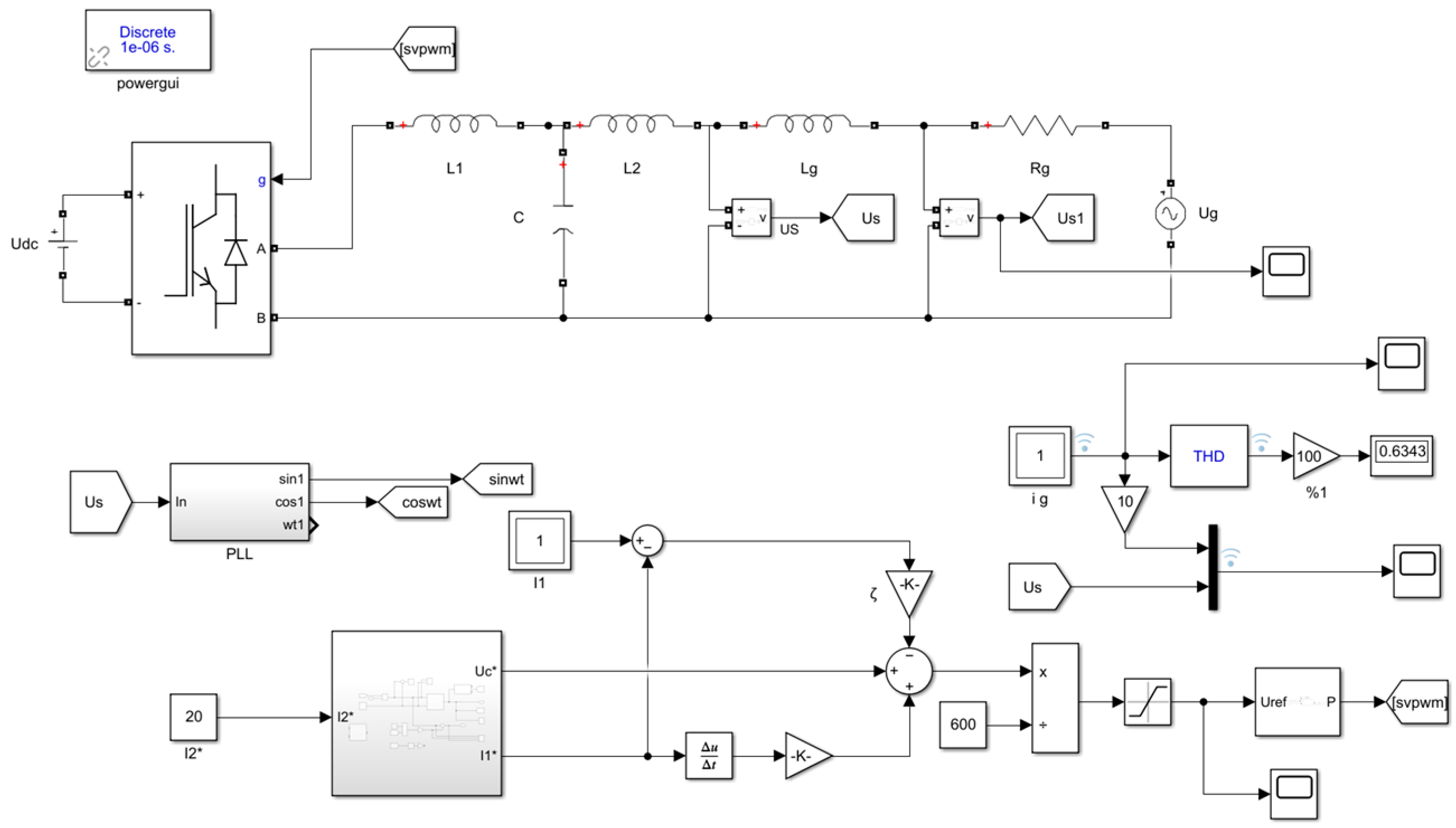
4. Simulation Analysis
In order to verify the feasibility of the control strategy proposed in the above theory, the system simulation model is built in Matlab/Simulink, as shown in Figure 7 and Figure 8. The single-phase weak grid LCL grid-connected inverter system is simulated and analyzed under three control modes, and the grid-connected current and the attenuation ability of the grid background harmonics are compared when the grid impedance changes. The three control methods are: (1) In the traditional double loop control, PR controller is used in the inner loop, kp and kr are proportional parameters and resonant parameters of PR controller, ke is the capacitive current feedback coefficient; (2) Passive active disturbance rejection controller without fuzzy control (ADRC + PBC); (3) The control proposed in this paper. The basic simulation parameters of the system are shown in Table 2.
Figure 7.
The overall simulation model of single-phase weak grid LCL grid-connected inverter.
Figure 8.
Fuzzy-ADRC module.
Table 2.
System Simulation Parameters.
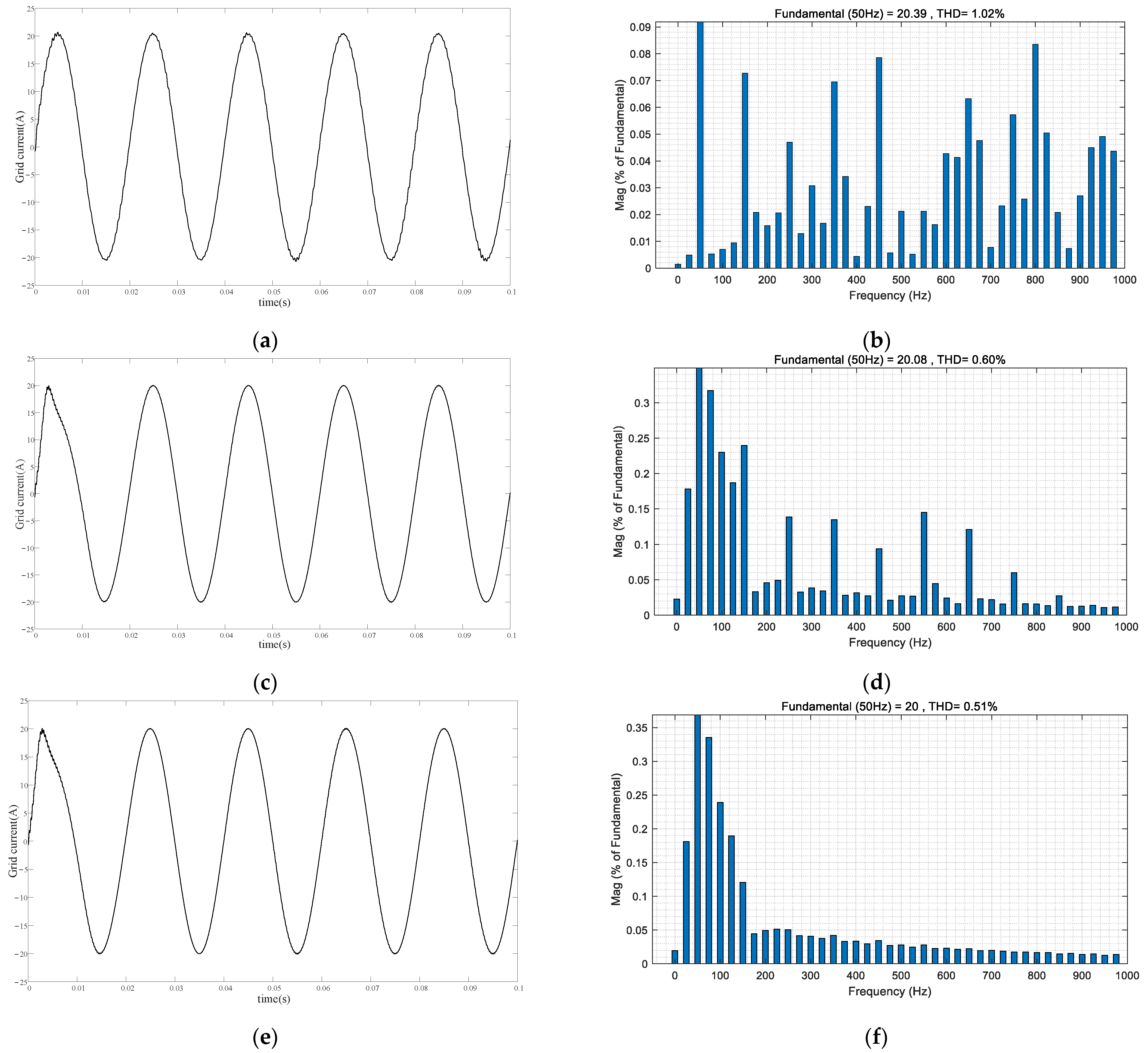
4.1. A. Simulation Results under Strong Grid Conditions
Under the strong grid, the grid impedance is very small, set Rg = 0.1 Ω, Lg = 0.5 mH, and the corresponding SCR = 52. The steady-state simulation analysis of a single-phase LCL grid-connected inverter system under three control modes is carried out. Since the set output power of the grid-connected inverter system is 3.1 kW, the grid-connected reference current is set to 20 A. The output grid-connected current waveforms and the corresponding harmonic analysis are shown in Figure 9. It can be seen from Figure 9 and Table 3 that under the condition of a strong power grid, the three control methods can make the grid-connected current output of the system follow the given current steadily, and the total harmonic distortion (THD) of the current is 1.02%, 0.6%, and 0.51% respectively, which are far less than the national standard of 5% grid-connected current harmonic standard, which shows that under the condition of the strong power grid, the three control methods can ensure the stable operation of the inverter. In addition, by comparing the three control methods, it can be seen that the steady-state grid-connected current waveform under the proposed control strategy is smoother and the current THD value is the smallest, which proves the superiority of the proposed control strategy.
Figure 9.
Simulation results under strong grid conditions. (a) Grid current under conventional control; (b) THD analysis of grid current under conventional control; (c) Grid current under ADRC + PBC; (d) THD analysis of grid current under ADRC + PBC; (e) Grid current under FUZZY-ADRC + PBC; (f) THD analysis of grid current under FUZZY-ADRC + PBC.
Table 3.
THD analysis of grid-connected current under strong grid conditions.
4.2. B. Simulation Results under Weak Grid Conditions
When the external environment changes in the simulated weak grid, the grid impedance increases so that Rg = 1 Ω, Lg = 14 mH, the corresponding SCR = 2.1, and the remaining parameters remain unchanged. The output steady-state grid-connected current waveforms and the corresponding harmonic analysis are shown in Figure 10.
Figure 10.
Simulation results under weak grid conditions. (a) Grid current under conventional control; (b) THD analysis of grid current under conventional control; (c) Grid current under ADRC + PBC; (d) THD analysis of grid current under ADRC + PBC; (e) Grid current under FUZZY-ADRC + PBC; (f) THD analysis of grid current under FUZZY-ADRC + PBC.
It can be seen from Figure 10 and Table 4 that the grid-connected current waveform has been seriously distorted under conventional control. At this time, the THD of the current becomes 25.92%, while the grid-connected current THD of the passive active disturbance rejection controller and the composite control strategy proposed in this paper are 2.49% and 0.51%, respectively, which still meet the national standard of 5% grid-connected current harmonic standard, and the control strategy proposed in this paper has a better ability to suppress harmonics. Therefore, the FUZZY-ADRC + PBC composite control strategy proposed in this paper still has good adaptability to the current weak grid and effectively improves the stability of the LCL grid-connected inverter.
Table 4.
THD analysis of grid-connected current under weak grid conditions.
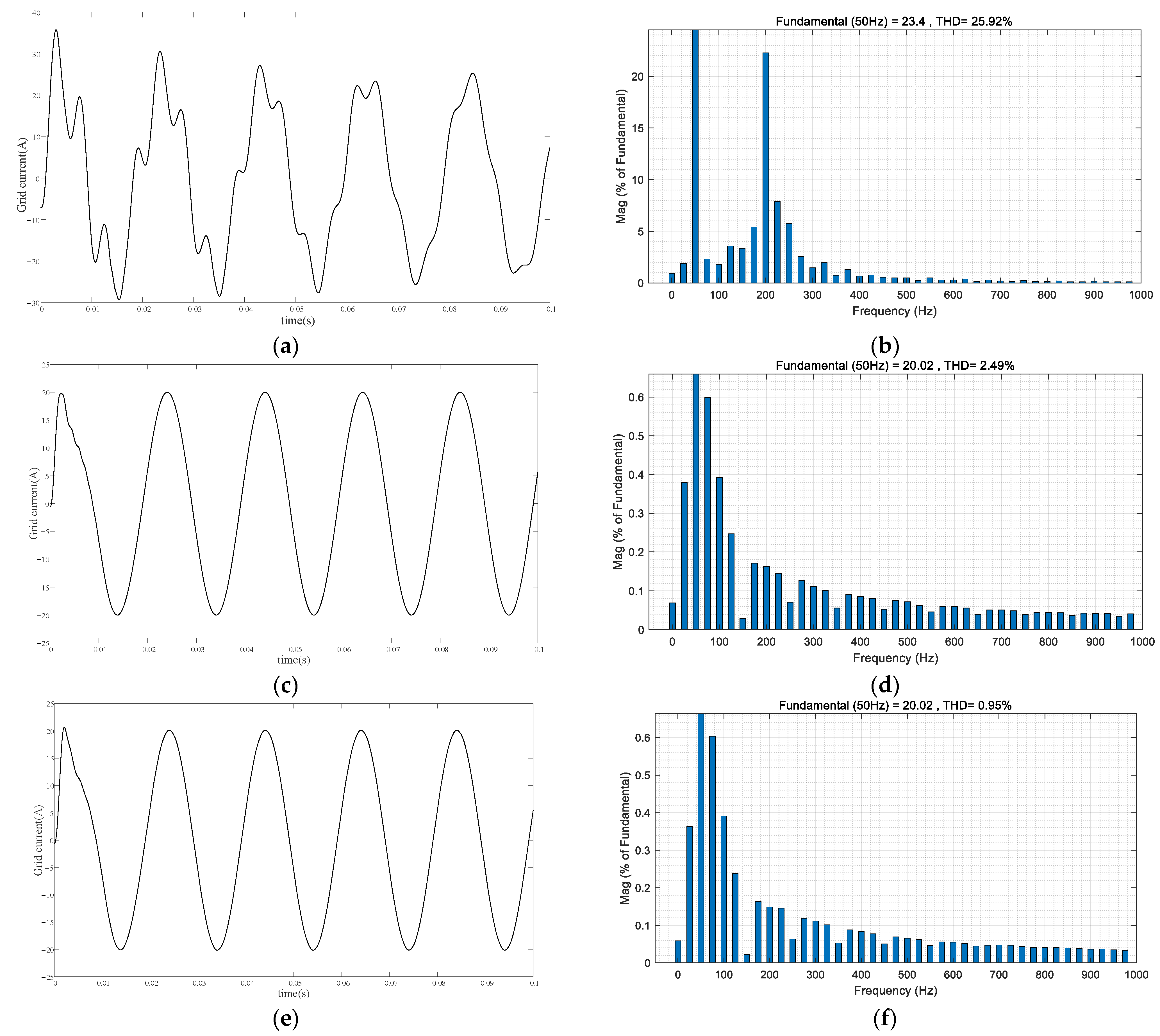
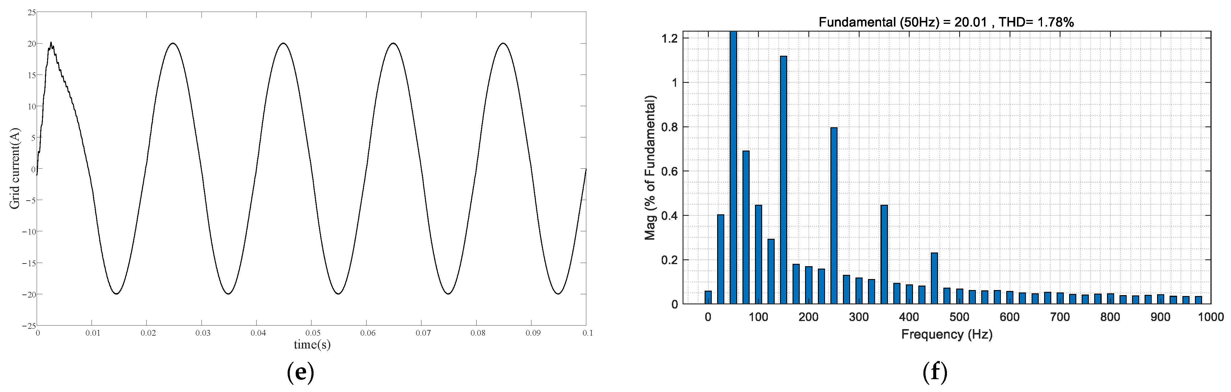
4.3. Grid Background Harmonic Simulation
In order to compare the attenuation ability of the three control methods to the background harmonics of the power grid, a series of third harmonics with amplitude of 5% of the grid voltage, 4% of the fifth harmonics, 3% of the seventh harmonics and 2% of the ninth harmonics are added to the grid voltage in the simulation. The simulation results are shown in Figure 11.

Figure 11.
Simulation results under grid background harmonics. (a) Grid current under conventional control; (b) THD analysis of grid current under conventional control; (c) Grid current under ADRC + PBC; (d) THD analysis of grid current under ADRC + PBC; (e) Grid current under FUZZY-ADRC + PBC; (f) THD analysis of grid current under FUZZY-ADRC + PBC.
From Figure 11 and Table 5, it can be seen that the grid-connected current has been distorted to a certain extent under conventional control, and its THD value is 10.86%, which does not meet the 5% grid-connected current harmonic standard of the national standard. The THD of the grid-connected current of the passive active disturbance rejection controller and the composite control strategy proposed in this paper is 2.43% and 1.78%, respectively, which can effectively suppress the background harmonics of the grid and ensure the quality of the grid-connected current. The harmonic suppression ability of the FUZZY-ADRC + PBC composite control strategy proposed in this paper is better and can better adapt to harsh conditions.
Table 5.
THD analysis of grid-connected current under the condition of grid background harmonics.
5. Conclusions
In this paper, the single-phase LCL grid-connected inverter under weak grid is taken as the research object. The passivity-based controller based on EL model is introduced to ensure the global stability of the system. For the problems of difficult tracking of the inverter side current and rich background harmonics in the grid voltage, the active disturbance rejection controller is used to track the grid-connected side current, and the control part is improved to simplify the parameter design process. The fuzzy control is added to realize the self-tuning function of the parameters, and the composite control strategy of the fuzzy-active disturbance rejection control grid current outer loop and the passivity-based control inverter current inner loop is given. The simulation results show that the composite control strategy ensures the global stability of the system, realizes the zero steady-state error tracking of the reference current, and has a good ability to suppress the grid-connected current harmonics, and can adapt to the change of grid impedance under different grid environments, which significantly improves the stability and robustness of the single-phase LCL grid-connected system under a weak grid. In future works, the influence of the phase-locked loop on the control performance can be considered, and the two-dimensional fuzzy controller can be used to adjust the system damping coefficient ξ1 adaptively to further improve the control performance of the system.
Author Contributions
H.Y. conceived the main concept of the control structure and developed the entire system; H.Y. carried out the research and analyzed the numerical data using guidance from H.C.; H.Y. and H.C. collaborated to prepare the manuscript. All authors have read and agreed to the published version of the manuscript.
Funding
This research was funded by the Innovation Fund for Industry University Research in Chinese Universities (grant number 2021ITA05025) and the National Natural Science Foundation of China (grant number 61473116).
Data Availability Statement
The data presented in this study are available on request from the corresponding author.
Conflicts of Interest
The authors declare no conflict of interest.
Abbreviations
| PBC | Passivity-based control |
| ADRC | Active disturbance rejection control |
| EL | Euler Lagrange |
| PI | Proportional integral control |
| PR | Proportional resonant control |
| TD | Tracking differentiator |
| ESO | Extended state observer |
| NLSEF | Nonlinear state error feedback control law |
| FUZZY-ADRC | Fuzzy-active disturbance rejection controller |
| SCR | Short circuit ratio |
| THD | Total harmonic distortion |
References
- Zhu, D.H.; Zhou, S.Y.; Zou, X.D.; Kang, Y.; Zou, K.F. Small-Signal Disturbance Compensation Control for LCL-Type Grid-Connected Converter in Weak Grid. IEEE Trans. Ind. Appl. 2020, 56, 2852–2861. [Google Scholar] [CrossRef]
- Li, J.G.; Zhang, Y.J.; Zhao, Y.M.; Ren, L.; Wang, J.H.; Liu, Y.F. An Improved Three-Stages Cascading Passivity-Based Control of Grid-Connected LCL Converter in Unbalanced Weak Grid Condition. IEEE Access 2021, 9, 89497–89506. [Google Scholar] [CrossRef]
- Gomes, C.C.; Cupertino, A.F.; Pereira, H.A. Damping techniques for grid-connected voltage source converters based on LCL filter: An overview. Renew. Sustain. Energy Rev. 2018, 81, 116–135. [Google Scholar] [CrossRef]
- Xue, T.Y.; Sun, P.J.; Xu, Z.Z.; Luo, Q.M. Feedforward phase compensation method of LCL grid-connected inverter based on all-pass filter in weak grid. IET Power Electron. 2020, 13, 4407–4416. [Google Scholar] [CrossRef]
- Wu, F.Y.; Sun, Z.; Xu, W.J.; Li, Z.Z.; Lyu, J.G. A Control Parameters Design Method With Multi-Constrains for an LCL-Filtered Grid-Connected Inverter in a Weak Grid. Front. Energy Res. 2022, 9, 1–13. [Google Scholar] [CrossRef]
- Karshenas, H.R.; Saghafi, H. Basic Criteria in Designing LCL Filters for Grid Connected Converters. 2006 IEEE Int. Symp. Ind. Electron. 2006, 3, 1996–2000. [Google Scholar] [CrossRef]
- Yang, X.Q.; Liu, X.Y.; Li, J.C.; Zhang, B.B. Current PI lambda Control of the Single-Phase Grid Inverter. Math. Probl. Eng. 2021, 2021, 1–9. [Google Scholar] [CrossRef]
- Fu, X.G.; Li, S.H. Control of Single-Phase Grid-Connected Converters With LCL Filters Using Recurrent Neural Network and Conventional Control Methods. IEEE Trans. Power Electron. 2016, 31, 5354–5364. [Google Scholar] [CrossRef]
- Li, Y.H.; Zhang, J.; Hao, Z.H.; Tian, P. Improved PR Control Strategy for an LCL Three-Phase Grid-Connected Inverter Based on Active Damping. Appl. Sci. 2021, 11, 3170. [Google Scholar] [CrossRef]
- Zhou, N.; Dong, Y.; Liao, J.; Wang, Q. Pole-mode Transformation of Bipolar DC Systems With Metallic Return and Its Application in Fault Analysis. Zhongguo Dianji Gongcheng Xuebao/Proc. Chin. Soc. Electr. Eng. 2021, 41, 130–142. [Google Scholar] [CrossRef]
- Yang, M.; Bao, J.; Sun, Y.; Wei, Y. Capacitor voltage feedforward control strategy of grid-connected inverter in weak grid. Taiyangneng Xuebao/Acta Energ. Sol. Sin. 2021, 42, 94–102. [Google Scholar] [CrossRef]
- Zhou, W.; Wang, Y.; Torres-Olguin, R.E.; Chen, Z. DQ Impedance Reshaping of Three-Phase Power-Controlled Grid-Connected Inverter for Low-Frequency Stability Improvement Under Weak Grid Condition. In Proceedings of the 2020 IEEE Energy Conversion Congress and Exposition (ECCE), Detroit, MI, USA, 11–15 October 2020; pp. 1678–1685. [Google Scholar] [CrossRef]
- Zhang, Q.; Cai, F.; Huang, L.; Chen, X. PI+ Repetitive Control Applied to Single-Phase Programmable Standard Power Source. Diangong Jishu Xuebao/Trans. China Electrotech. Soc. 2019, 34, 163–170. [Google Scholar] [CrossRef]
- Lv, Z.K.; Sun, L.; Duan, J.D.; Duan, M.H.; Pei, H.J. A novel harmonic impedance compensator based on POHMR-type RC under gird voltage distortion. Int. J. Electr. Power Energy Syst. 2020, 124, 106352. [Google Scholar] [CrossRef]
- Eren, S.; Pahlevaninezhad, M.; Bakhshai, A.; Jain, P.K. Composite Nonlinear Feedback Control and Stability Analysis of a Grid-Connected Voltage Source Inverter With LCL Filter. IEEE Trans. Ind. Electron. 2013, 60, 5059–5074. [Google Scholar] [CrossRef]
- Xie, C.; Li, K.; Zou, J.X.; Guerrero, J.M. Passivity-Based Stabilization of LCL-Type Grid-Connected Inverters via a General Admittance Model. IEEE Trans. Power Electron. 2020, 35, 6636–6648. [Google Scholar] [CrossRef]
- Akhavan, A.; Mohammadi, H.R.; Vasquez, J.C.; Guerrero, J.M. Passivity-Based Design of Plug-and-Play Current-Controlled Grid-Connected Inverters. IEEE Trans. Power Electron. 2020, 35, 2135–2150. [Google Scholar] [CrossRef]
- Zhou, W.; Torres-Olguin, R.E.; Wang, Y.; Chen, Z. A Gray-Box Hierarchical Oscillatory Instability Source Identification Method of Multiple-Inverter-Fed Power Systems. IEEE J. Emerg. Sel. Top. Power Electron. 2021, 9, 3095–3113. [Google Scholar] [CrossRef]
- Wang, B.C.; Shen, Z.Y.; Liu, H.; Hu, J.H. Linear ADRC direct current control of grid-connected inverter with LCL filter for both active damping and grid voltage induced current distortion suppression. IET Power Electron. 2018, 11, 1748–1755. [Google Scholar] [CrossRef]
- Lu, W.; Li, Q.; Lu, K.; Lu, Y.; Guo, L.; Yan, W.; Xu, F. Load Adaptive PMSM Drive System Based on an Improved ADRC for Manipulator Joint. IEEE Access 2021, 9, 33369–33384. [Google Scholar] [CrossRef]
- Cai, Y.X.; He, Y.J.; Zhou, H.W.; Liu, J.J. Active-Damping Disturbance-Rejection Control Strategy of LCL Grid-Connected Inverter Based on Inverter-Side-Current Feedback. IEEE J. Emerg. Sel. Top. Power Electron. 2021, 9, 7183–7198. [Google Scholar] [CrossRef]
- Ma, Y.; Tao, L.; Zhou, X.; Hong, F.; Shi, X.; Zhao, H. Fuzzy adaptive control of voltage loop in wind power system combined with linear active disturbance rejection control. Taiyangneng Xuebao/Acta Energ. Sol. Sin. 2020, 41, 330–337. [Google Scholar]
- Ma, M.; Liao, P.; Cai, Y.; Lei, E.; He, Y. Active Disturbance Rejection Control Strategy of LCL Grid-connected Inverter. Gaodianya Jishu/High Volt. Eng. 2021, 47, 2223–2231. [Google Scholar] [CrossRef]
- Li, P.; Wang, J. Control Strategy of Vienna Rectifier Based on Passivity-based and Active Disturbance Rejection Controller. Dianwang Jishu/Power Syst. Technol. 2022, 46, 1575–1584. [Google Scholar] [CrossRef]
Disclaimer/Publisher’s Note: The statements, opinions and data contained in all publications are solely those of the individual author(s) and contributor(s) and not of MDPI and/or the editor(s). MDPI and/or the editor(s) disclaim responsibility for any injury to people or property resulting from any ideas, methods, instructions or products referred to in the content. |
© 2023 by the authors. Licensee MDPI, Basel, Switzerland. This article is an open access article distributed under the terms and conditions of the Creative Commons Attribution (CC BY) license (https://creativecommons.org/licenses/by/4.0/).