Abstract
Turbomolecular pumps (TMPs), boasting advantageous high pumping rates, stability, and cleanliness, have been widely used in the semiconductor and photoelectric industries. In the aviation industry, the lightweight rotors of turbomolecular pumps can enhance the performance of generators. With technological advancements and increased industrial performance demands, various designs for turbomolecular pump rotors utilizing twisted and curved blade surfaces have been proposed. This increase in complexity runs parallel with machining difficulties. Contact and noncontact reverse engineering equipment was used to reconstruct a computer-aided design (CAD) model of turbomolecular pump rotors. The machining of thin and long blades, cutting tool arrangement, and toolpath was planned. Postprocessing was used to convert the toolpath into numerical control (NC) programming codes, which were combined with solid model cutting simulation software to verify the efficacy of the generated machining NC program for turbomolecular pump rotors. A five-axis horizontal machining center (CK type) with aluminum alloy AL6061-T6 was used to conduct actual machining tests measuring the efficiency of the machining methods. The rapid prototyping (RP) blocks can be creatively used as a jig and stuffed between the blades to suppress the chatter problem during processing, and the roughness of the surface of the blades can be reduced from 4.4 μm to 1.3 μm. The processed rotor can meet the flow test requirements, and the overall research can be used as a reference for the industry.
1. Introduction
Gaede introduced the drum molecular pump structure in 1913 [1]. In 1958, Becker further developed blade turbomolecular pumps [2], which exhibited extremely high performance in 10−3 Torr molecular flows. With its high pumping rate, compression ratio, and cleanliness, the turbomolecular pump rapidly replaced traditional positive displacement vacuum pumps and was widely applied in the semiconductor manufacturing or photoelectric industries [3,4,5,6].
Turbomolecular pumps comprise twin-rotor horizontal and single-rotor vertical systems, with rotors and stators interleaved in assembly design [2,5,7]. Rotors rotate rapidly, enabling gas to collide with the blades and transmit kinetic energy. The working pressure begins from 10−3 Torr, and the final pressure can reach 10−8 or 10−9 Torr. Sengil [8] illustrates that different blade designs can be used to enhance performance through improvements in the pumping rate and compression ratio. With modern advancements, the manufacturing process of semiconductors has undergone considerable development, which in turn has increased the performance requirements of vacuum pumps. The designs of turbomolecular pumps have become more diverse, with the concurrent difficulty of machining highly dependent on the design.
In the aviation industry, the performance of generators determines the functions and purposes of aircraft. The bladed rotor or blisk of turbomolecular pumps is a crucial and novel component in modern aircraft generators. It is favored for its lightweight design, integrated bladed disks [9], high pneumatic efficiency, and increased service life. However, this component is costly and difficult to produce. Bussmann and Bayer [10] described the technological development of the integrated compressor impeller and blisk in contemporary engine structures. They also identified the future technological applications of blisks, accounting for the challenges in terms of their function, quality, and cost. Because the blade has an intricate twisted and curved surface, multi-axis machining has proven more advantageous than traditional triaxial machining [11].
However, owing to the synchronous motion of the cutting tools, the application of multi-axis machine tools is complex and can result in the interference or collision of the cutting tools with the curved surface [12,13]. Klocke et al. [14] analyzed the technical and economic costs of the material removal rate of rough machining through milling, electrical discharge machining, and electrochemical machining on blisks made of titanium alloy Ti-6Al-4V and nickel base alloy 718. Milling is the most cost-effective of the many machining techniques used for titanium alloy blisks.
Chaves-Jacob et al. [15] proposed optimization strategies for impeller blade finishing and examined the deformation resulting from geometric errors using different ball-nose end mills in machining methods such as point contact cutting, flank milling, and multipath flank milling. Its geometrical error indicates a deviation between the machined surface and the nominal surface. The feed rate greatly affects the cutting forces and, thus, the deflections of the blade and tool during machining, which in turn affects the geometric errors caused by these deflections. They also conducted experiments with titanium alloy to measure radial cutting forces. The machining path length is typically divided by the maximum feed rate to determine the machining time, and the ideal feed rate is defined to avoid geometric errors arising from the deviation of the cutter. The three indicators (a flow indicator, a mechanical indicator, and a machining indicator) can evaluate whether the machining strategy meets the geometric function requirements.
To further demonstrate the pneumatics of impellers and blisks with an increasing number of blades and increasingly complicated curved blade surface geometry errors, the present study employed three-dimensional (3D) scanners and incorporated reverse engineering and five-axis machining techniques to design new models for industrial development. Zhao et al. [16] conducted reverse modeling and five-axis machining experiments on aircraft engine impellers, revealing that the machined sample and research model had an error lower than 0.06 mm. In addition, She and Chang [17] used 3D measurement devices to obtain geometric point data, which they then used to generate turbo blade CAD models in the CAD and computer-aided machining (CAM) system of Unigraphics (UG). Discarding the CAM module of the UG software, they applied the UG Graphics Interactive Programming language to generate the cutter machining paths, the efficacy of which was then verified using the cutting simulation software VERICUT [18,19].
The objectives of this study are to reverse engineer the rotors of turbomolecular pumps, rebuild 3D solid models of the rotors using the CAD/CAM system, and plan the machining process and paths. Subsequently, the cutting simulation software VERICUT was used to confirm the NC code path. A five-axis horizontal machining center (CK type) was applied to machine an aluminum alloy (AL6061-T6) solid sample to evaluate the efficiency of the machining process and methods. This work also attempts to improve TMP processing.
2. Experimental Methods
This study evaluated the feasibility of manufacturing a turbomolecular pump rotor with nine turbine stages that have been applied in semiconductor vacuum pumps. The longest blade length of this rotor is 100 mm, and the shortest blade length is 35 mm. The total length of the nine stages is 149 mm. However, it is extremely complicated and difficult to create a 3D model for a new design of a turbomolecular pump rotor, and this will also involve aerodynamics. When it is damaged and needs to be remanufactured, reverse engineering technology can be applied to replicate the turbomolecular pump rotor without obtaining the engineering drawing. The coordinate measuring machine (CMM) ZEISS CONTURA RDS 7106 (ZEISS, Oberkochen, Germany) and noncontact 3D scanner AICON SmartScan-HE (AICON, Braunschweig, Germany) for reverse engineering were applied to extract the data of the rotor sample profiles. They will be able to overcome the results of the interference scanning of the blades of various stages under the multi-stage turbine blades scanned by a single non-contact scanner. The measurement accuracy of the two is about 0.007 mm and 0.03 mm, respectively. Then, reverse engineering software Geomagic Studio 2012 and Geomagic Qualify 2012, for inspection purposes, were used to position the data and compare errors. Siemens NX CAD 12.0 software was employed to import the data for the subsequent fitting of curves and curved surfaces and reconstruction of the complete 3D solid model of the blade CAD models [20,21,22]. Siemens NX CAM 12.0 [23,24] was used to program and plan the process of the rotor machining paths and cutter arrangement. Cutting simulation verification software VERICUT 7.4.1 was then applied to verify whether the toolpaths exhibited overcutting, collision, or abnormal mechanical motion. A five-axis horizontal machining center was used to mill an aluminum alloy block in order to obtain the turbomolecular pump rotor. Finally, the process efficiency and machining methods were evaluated; the research flowchart is sketched in Figure 1.
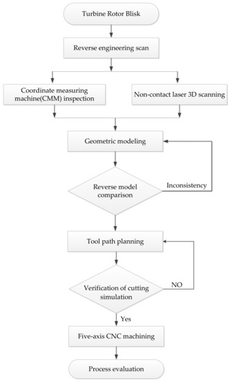
Figure 1.
Flowchart of the research process.
2.1. Geometric Reconstruction of Reverse Engineering
Because the geometry of the turbomolecular pump rotor is too complicated to be reverse modeled in one operation, both a contact coordinate measuring machine and a noncontact scanner were employed to extract point coordinate data of the hub and blade separately. The extracted results needed to be positioned and restructured.
2.1.1. Coordinate Measurement
To construct the rotor profiles of the turbomolecular pump, a CMM was used to manually measure the outer contour size and the inner bore of the rotor. The sample surface profile positions were recorded with respect to geometric features, including planes, circles, and cones. Displacements of the geometric features were computed to determine the profile dimensions of the hub. The measurement results of the profiles were applied to reconstruct the 3D solid model using the graphic software NX CAD, determining the accurate blade thickness of nine turbine stages and the corresponding position on the hub, as illustrated in Figure 2.

Figure 2.
Coordinate measuring machine used for measuring the surface profile and reconstruction of the solid model. (a) Blade thickness and stage-interval measurements; (b) reconstruction of the 3D solid model obtained using CAD software.
2.1.2. Noncontact 3D Scanning
The rotor blade geometry is a freeform surface. Data extraction was mainly performed using the 3D blue light scanner. The intervals between the fifth to ninth turbine stages were too short to extract complete blade geometry data. Therefore, the turbomolecular pump rotor was segmented into six parts, as depicted in Figure 3, with each part scanned separately to extract the complete geometry data of different turbine stages of the rotor. As presented in Figure 4, the scanner error (noise) on the first-stage and second-stage blades was compensated to provide a more smooth arrangement of points and curved surface fitting. After fitting was complete, the image was exported as an STL (STereoLithography) file to facilitate reconstruction of the solid CAD model
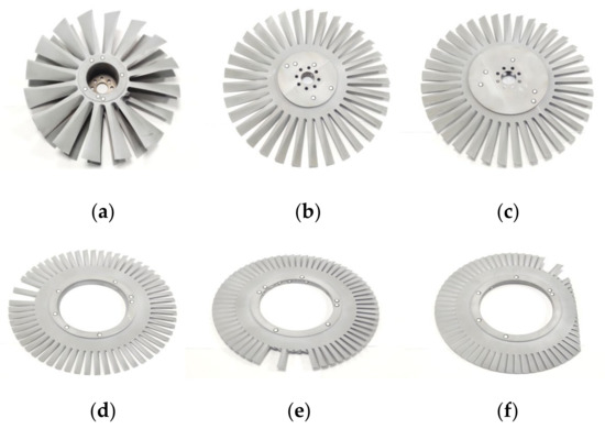
Figure 3.
Segmentation of the TMP rotor into six parts for non-contact 3D scanning. (a) First-stage and second-stage blades; (b) third-stage blade; (c) fourth-stage blade; (d) fifth-stage blade; (e) sixth-stage blade; (f) seventh-stage, eighth-stage, and ninth-stage blades.
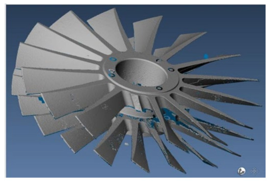
Figure 4.
Scanner error (noise) repair and surface fitting after scanning of the first and second turbine stages.
2.1.3. CAD Model Positioning and Reconstruction
Following coordinate measurement and noncontact scanning, CAD model positioning and reconstruction were conducted. Since the coordinates identified using the two measuring devices differed, the curve surface editing function of the Geomagic Studio was employed to align the STL files of all turbine stages obtained using a 3D scanner with the XYZ coordinate axes drawn by NX CAD. Finally, the file was exported as an IGS file for the reconstruction of the CAD model. Figure 5a illustrates the positioning of the first and second turbine stages. After positioning and file transformation for the entire assembly were performed, the files were exported to the NX CAD. According to the degree of curvature of the blade, the blade geometric model was reconstructed, as depicted in Figure 5b.
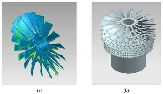
Figure 5.
CAD model of rotor reconstruction. (a) Positioning of the first and second turbine stages; (b) reconstruction of the curved surface circular array and Boolean combination.
2.1.4. Comparison of Model Errors
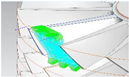
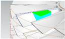
Following the rotor CAD model construction, the model accuracy was verified. Reverse engineering software Geomagic Qualify was employed to compare the errors of the scanned data of the rotor CAD and blades to identify any abnormalities or inconsistencies in the CAD and sample positions, dimensions, and geometries. The set nominal range ±0.1 mm and critical value ±0.5 mm are based on the manufacturer’s requirements and cannot be lower than the scanner’s specifications. These settings were compared to ensure that all turbine blades satisfied the precision requirements. If the comparison results are inconsistent, the CAD model shall be corrected. The comparison results are presented in Figure 6. It can be found that the deviation values are almost all within ±0.1 mm. In fact, the point data at the edge of the scanned object will be scattered, so it is reasonable to expect a higher deviation value at the tip of the blade.
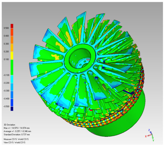
Figure 6.
Error comparison results.
2.2. Processing of Turbomolecular Pump Rotor
In the toolpath, turbomolecular pump rotor machining was divided into the following five parts: blade groove rough machining, blade curve surface semiroughing, blade curve surface finishing, hub semiroughing, and hub finishing. The five-axis simultaneous machining was applied to all five paths. Groove rough machining used an end mill, while the other toolpaths involved the use of ball nose end mills. Standard length (80 mm) or elongated cutting tools (100–150 mm) from CMTec Taiwan were selected for machining according to the designated range. However, the width of the blade groove will be greater at the tip of the blade and narrower near the root of the blade. Therefore, the diameter of the end mill will decrease with the distance from the root of the blade in milling the groove between the blades. The diameter of the end mill is reduced from 12 mm to 4 mm for the 1st–4th stage blades; the diameter is in the range of 2–4 mm for the 5th–9th stage blades. Ball nose end mills with a diameter of 8 mm and 4 mm are used to process the blades and hubs of the 1st–2nd and 3rd–4th stage of the rotor blades, respectively. Ball nose end mills with smaller diameters (2–4 mm) process the curved surfaces of the 5th–9th stage blades and hubs. The machining of the integral turbomolecular pump rotor used 17 tools.
In toolpath planning, the rotor blades were thin and long, leading to the possibility of generating considerable vibration. To reduce vibration and ensure the rigidity of the cutting tools, the toolpaths of the blades were divided into four segments according to the blade length. The first two segments were machined using cutting tools of standard lengths, whereas the other two segments were machined using elongated cutting tools. Taking the first-stage turbine blades as an example, the toolpath is summarized in Table 1.

Table 1.
Toolpath planning for of the turbomolecular pump rotor.
- Blade groove rough machining
Groove rough machining employs end mills to perform five-axis simultaneous machining. To avoid shortening the service life of the cutting tool, and to reduce vibrations resulting from overly lengthy clamps, the toolpath planning of the first two segments involved the use of a standard-length cutting tool at a spindle speed of 4000 rpm, feed rate of 1600 mm/min, cutting depth of 1 mm, and cutting width of 4.8 mm. The first two segments were 0–13% and 11–40% of the length of the blade. The other two segments were cut as 35–70% and 65–95% of the length of the blade using elongated cutting tools with a spindle speed of 6000 rpm, feed rate of 1200 mm/min, cutting depth of 0.3 mm, cutting width of 4.8 mm, and reserve of 0.5 mm.
- 2.
- Blade curve surface semiroughing
The semiroughing reserve was set at 0.3 mm. Along the rough toolpath, a conical ball end mill and five-axis simultaneous machining were used for cutting. The toolpath was divided into four segments. The first two segments were machined using cutting tools with a standard length of 0–11% and 9–36% of the blade length, and the other two segments were machined using elongated cutting tools at a length of 34–66% and 65–93% that of the blade. A spindle speed of 6000 rpm, feed rate of 1200 mm/min, and cutting depth of 0.01 mm were applied consistently for all segments.
- 3.
- Hub semiroughing
Hub semiroughing involved semiroughed grooving on the blade hub. Because the end mill in rough machining had shape limits and the cutting depth could not reach the hub of the blade, a ball nose end mill with an elongation of 110 mm was used to groove cut the workpiece during semiroughing. The cutting depth was 93–100% of the blade length, and the reserve was set at 0.3 mm. The spindle speed was 6000 rpm, the feed rate was 1200 mm/min, and the cutting depth was 0.1 mm.
- 4.
- Blade curve surface finishing
A ball nose end mill with an elongation of 110 mm was used to machine the full length of the blade in a nonsegmented fashion. The spindle speed was set as 6000 rpm, the feed rate as 1200 mm/min, and the residual height as 0.005 mm.
- 5.
- Hub finishing
The residue material at the bottom of the hub was removed from this toolpath. A ball nose end mill with an elongation of 110 mm was used to machine a small plane on the blade hub. The spindle speed was set as 6000 rpm, the feed rate as 1200 mm/min, and the residual height as 0.005 mm.
The jig is essential in the machining process and clamps or fixes the workpieces on the machining platform to limit the freedom of movement of the raw materials. If workpieces cannot be secured during machining, errors, position deviation, and dimension errors can occur. The jig must be designed to securely fix the position of the workpiece and minimize the effect on the operation range of machining. The fixture jig used in this study is currently designed in reference to the geometry of the inner bore surface of the rotors. The engineering tolerance of the clearance of 0.03 mm was obtained to ensure clearance fit of the rotor and jig fixture. An adapter board was used to fix the rotor on the jig of the mill machine, as depicted in Figure 7. The Ø24 mm through hole on the hub of the rotor is used for fine positioning during assembly with the jig. The surrounding eight holes can be used to fasten the rotor to the jig with eight M6 screws.
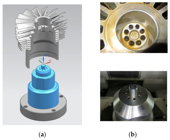
Figure 7.
Jig design. (a) Schematic diagram of rotor and jig assembly; (b) combination with screws and pin positioning.
3. Cutting Simulation, Verification, and Multi-Axis Machining
3.1. Verification of Cutting Simulation
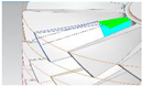
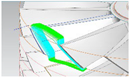
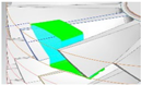
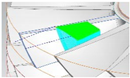
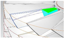
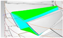
Because the geometry of milling was complicated, VERICUT software was used to simulate the NC code of the toolpaths after postprocessing conversion to verify that no collision, overcutting, or NC data procedural error occurred in the simulation results. The engineering tolerance was set to ±0.1 mm. Geometry error matching functions (Auto-Diff) were used to match toolpath overcutting and the margin to ensure the toolpath NC code satisfied the engineering tolerance precision and dimensions requirements. The results, as presented in Figure 8, revealed no overcutting.
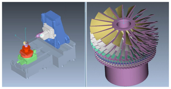
Figure 8.
Verification of solid model cutting simulation.
3.2. Multi-Axis Machining
The five-axis horizontal machining center Tongtai HB-630SE(Tongtai, Kaohsiung, Taiwan) was used to cut the turbomolecular pump rotor. The blank was aluminum alloy AL6061-T6(Sheng Kwang Aluminium Co. Ltd., Kaohsiung, Taiwan) with a height of 269 mm and a maximum diameter of 300 mm. A CNC lathe was first used to cut the nine stages of the blade blanks, as depicted in Figure 9. Table 2 lists the blade number of each stage and the machining time. The total machining time was 18 days and 23 h. The machining process and final product are illustrated in Figure 10. The average current measured during processing was about 15A, and the total processing power consumption was about 4500 KWH.
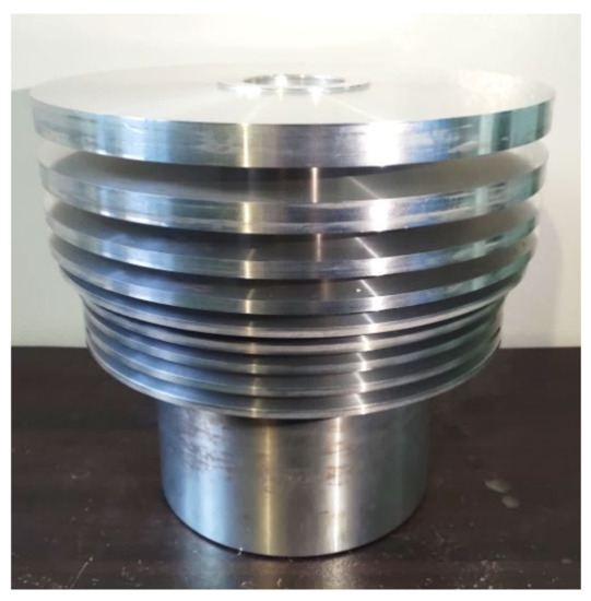
Figure 9.
Blank of AL6061-T6 after lathing.
Table 2.
Rotor machining time.
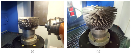
Figure 10.
Final product of the turbomolecular pump rotor. (a) Rotor machining process; (b) final product of the turbomolecular pump rotor.
4. Results and Discussion
The Auto-Diff geometry error matching function of VERICUT was used to compare the margin and overcutting. The maximum margin of 0.4 mm was generated at the second-stage blade, marking the path for the tool to leave the root during finishing. A residue was generated due to limitations of the tool rotation direction; the cutting toolpath must thus be adjusted to solve the problem.
The initial machining plan was to conduct semiroughing on different segments of the blade and then to machine finishing paths. However, the machining results indicated that the transition of the paths on the curved surface of the blade of each segment presented apparent joints. Therefore, the path plan was changed, and finishing of the full length of the blade following the semiroughing of each segment was performed.
The first four stages’ blades near the tip exhibited poor surface quality resulting from the machining vibration induced by the clamp length of the finishing cutting tools and blade design, as shown in Figure 11a. The surface roughness is 4.4 μm. Even changing the processing parameters, such as the cutting depth, feed rate, and spindle speed, failed to improve the quality. In order to limit the freedom of the opposing blades and suppress chatter during machining, several block jigs were designed, as shown in Figure 12. This block was printed through RP with stereolithography resin, and the size of its outline could be determined by the blade surface and stage distance of the CAD model. These blocks can be used to finish the curved surface of the blade. Since there will be a reserve of 0.5 mm after the rough machining of the blade, a block jig can be inserted between the blades during processing to support the blade.
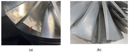
Figure 11.
Chatter results can be suppressed or solved when the RP blocks are stuffed between the blades in finishing. (a) Chatter occurs on the blade surface, as indicated by the arrow; (b) better surface quality on the blade surface.
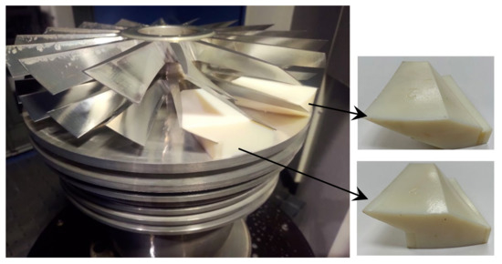
Figure 12.
Jig machining condition.
Figure 11b shows that the machining of the stuffed RP solids leads to a good improvement in the surface quality of the blade, and the surface roughness is reduced from 4.4 μm to 1.3 μm. However, because the blade number at the fifth stage to the ninth stage was high, the filling method had low overall efficiency. The spindle speed was adjusted to under 6000 rpm to effectively improve the blade surface quality.
The processed turbomolecular pump rotor was tested according to the flow test standard in the industry, and the relationship between chamber pressure and flow was determined, as shown in Figure 13. Compared with the original TMP rotor, there are consistent characteristics in the variation of chamber pressure with the flow.
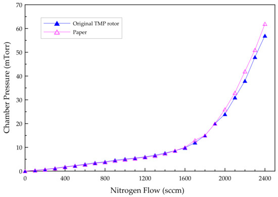
Figure 13.
The variation of chamber pressure with the flow for the processed and the original TMP rotors.
5. Conclusions
This study used contact and noncontact reverse engineering devices to measure the dimensions and extract data from different turbomolecular pump rotor components. The proposed method considerably reduced the reverse engineering time. In addition, reverse engineering software was used to unify, position, and compare errors of workpieces to increase the precision of rotor model construction. After appropriate machining methods were applied, solid model cutting simulation was used to verify blade precision and path planning. These simulations were used to examine the machine operations of the toolpath NC codes and avoid machine–tool collision, overcutting, or NC data procedural errors, thus achieving the set requirements. Although sufficient preprocessing procedures were conducted, machining vibration would still need to be addressed to improve machining surface quality in the five-axis machining process. Vibrations were addressed through the use of an RP block, which can be used for the first four stages, allowing for high spindle speed and feed rates. Using these RP blocks reduced machining vibration and increased machining surface quality, enhancing the overall machining efficiency. The remaining turbine stages contain shorter blades and, therefore, cannot be accommodated with an RP block. They must have their spindle speed reduced in order to minimize vibrations during machining. Finally, the flow test was carried out for the processed turbomolecular pump rotor; it met the requirements of the company.
Author Contributions
Conceptualization, J.-N.L.; methodology, T.-H.C.; software, M.-J.S. and Y.-C.C.; validation, T.-H.C. and J.-N.L.; formal analysis, J.-N.L.; investigation, T.-H.C.; re-sources, J.-N.L.; data curation, T.-H.C., M.-J.S. and Y.-C.C.; writing—original draft preparation, T.-H.C.; writing—review and editing, T.-H.C.; All authors have read and agreed to the published version of the manuscript.
Funding
This research received no external funding.
Data Availability Statement
The data presented in this study are available on request from the corresponding author.
Conflicts of Interest
The authors declare no conflict of interest.
References
- Dorothy, M.H.; Singh, B.; Thomas, J.H. Handbook of Vacuum Science and Technology; Academic Press: Cambridge, MA, USA, 1998; pp. 183–213. [Google Scholar]
- Jousten, K. Handbook of Vacuum Technology; Wiley-VCH: Weinheim, Germany, 2008. [Google Scholar]
- Nagaoka, T.; Mase, M. Application of a Dry Turbo Vacuum Pump to Semiconductor Manufacturing Processes. J. Vac. Sci. Technol. B Nanotechnol. Microelectron 1994, 12, 2830–2834. [Google Scholar] [CrossRef]
- Ino, K.; Sekine, K.; Shibata, T.; Ohmi, T.; Maejima, Y. Improvement of Turbomolecular Pumps for Ultraclean, Low-pressure, and High-gas-flow Processing. J. Vac. Sci. Technol. A Vac. Surf. Films 1998, 16, 2703–2710. [Google Scholar] [CrossRef]
- Huang, Z.; Han, B.; Mao, K.; Peng, C.; Fang, J. Mechanical Stress and Thermal Aspects of the Rotor Assembly for Turbomolecular Pumps. Vacuum 2016, 129, 55–62. [Google Scholar] [CrossRef]
- Lian, Y. Semiconductor Microchips and Fabrication: A Practical Guide to Theory and Manufacturing; Wiley-IEEE Press: Hoboken, NJ, USA, 2022. [Google Scholar]
- O’Hanlon, J.F. A User’s Guide to Vacuum Technology, 3rd ed.; John Wiley & Sons Inc.: Hoboken, NJ, USA, 2003. [Google Scholar]
- Sengil, N. Performance increase in turbomolecular pumps with curved type blades. Vacuum 2012, 86, 1764–1769. [Google Scholar] [CrossRef]
- Ravikumar, B.V.R. A Review of BLISK Technology. Int. J. Innov. Res. Sci. Technol. 2013, 2, 1353–1358. [Google Scholar]
- Bussmann, M.; Bayer, E. BLISK Production of the Future-technological and Logistical Aspects of Future-oriented Construction and Manufacturing Processes of Integrally Bladed Rotors. In Proceedings of the 19th International Symposium on Airbreathing Engines, Montreal, QC, Canada, 7–11 September 2009; pp. 568–576. [Google Scholar]
- Tsay, D.M.; Her, M.J. Accurate 5-axis Machining of Twisted Ruled Surfaces. J. Manuf. Sci. Eng. 2001, 123, 731–738. [Google Scholar] [CrossRef]
- Li, S.X.; Jerard, R.B. 5-axis Machining of Sculptured Surfaces with a Flat-end Cutter. Comput. Aided Des. 1994, 26, 165–178. [Google Scholar] [CrossRef]
- Yan, B.; Hao, Y.; Zhu, L.; Liu, C. Towards High Milling Accuracy of Turbine Blades: A Review. Mech. Syst. Signal Process. 2022, 170, 108727. [Google Scholar] [CrossRef]
- Klocke, F.; Zeis, M.; Klink, A.; Veselovac, D. Technological and Economical Comparison of Roughing Strategies via Milling, EDM and ECM for Titanium- and Nickel-based Blisks. Procedia CIRP 2012, 2, 98–101. [Google Scholar] [CrossRef]
- Chaves-Jacob, J.; Poulachon, G.; Duc, E. Optimal Strategy for Finishing Impeller Blades Using 5-axis Machining. Int. J. Adv. Manuf. Technol. 2012, 58, 573–583. [Google Scholar] [CrossRef]
- Zhao, X.; Pan, J.; Li, L. Research of Integrated Impeller Modeling and Five-axis Machining Technology Based on Reverse Engineering. J. Phys. Conf. Ser. 2021, 1865, 032037. [Google Scholar] [CrossRef]
- She, C.H.; Chang, C.C. Study of Applying Reverse Engineering to Turbine Blade Manufacture. J. Mech. Sci. Technol. 2007, 21, 1580–1584. [Google Scholar] [CrossRef]
- VERICUT. Vericut Online Help Version 7.4-OptiPath API; Version 7.4.1; CGTech: Irvine, CA, USA, 2015. [Google Scholar]
- Lu, H.; Cai, Y.J.; Li, G.H. Study on Rough Machining Strategy and Vericut Simulation of Integral Impeller Based on UG, Mat. Eng. and Mech. Eng. In Proceedings of the Material Engineering and Mechanical Engineering (MEME2015), Hangzhou, China, 23–25 October 2015; pp. 666–673. [Google Scholar]
- Heo, E.Y.; Kim, D.W.; Lee, J.Y.; Kim, K.Y. Computer-aided Measurement Plan for an Impeller on a Coordinate Measurement Machine with a Rotating and Tilting Probe. Robot. Comput.-Integr. Manuf. 2008, 24, 788–795. [Google Scholar] [CrossRef]
- Riyadi, T.W.B.; Yulianto, Y.H.; Effendy, M.; Sarjito; Zheng, Z.; Ping, T.L. Evaluation on a Digitized CAD Model of 3D Scanner Used in Reverse Engineering. In Proceedings of the 12th South East Asian Technical University Consortium (SEATUC), Yogyakarta, Indonesia, 12–13 March 2018; Volume 1, pp. 1–5. [Google Scholar]
- Chang, K.H.; Chen, C. 3D Shape Engineering and Design Parameterization. Comput. Aided Des. Appl. 2011, 8, 681–692. [Google Scholar] [CrossRef]
- Li, Z.; Zhang, Y. Multiaxial Machining Technology of Mechanical Parts Based on UG/CAM. Acad. J. Manuf. Eng. 2018, 16, 64–72. [Google Scholar]
- Li, H.Y.; Wang, X.M.; Shi, J.D.; Cao, Y.S.; Li, D. NX CAM Programaming Multi-Axis Machining Practice Guide; Tsinghua University Press: Beijing, China, 2014. (In Chinese) [Google Scholar]

Disclaimer/Publisher’s Note: The statements, opinions and data contained in all publications are solely those of the individual author(s) and contributor(s) and not of MDPI and/or the editor(s). MDPI and/or the editor(s) disclaim responsibility for any injury to people or property resulting from any ideas, methods, instructions or products referred to in the content. |
© 2023 by the authors. Licensee MDPI, Basel, Switzerland. This article is an open access article distributed under the terms and conditions of the Creative Commons Attribution (CC BY) license (https://creativecommons.org/licenses/by/4.0/).