Article

Reconfigurable Amplitude-Phase-Coding Metasurface with Flexible Beamforming Capability

1
National Key Laboratory of Science and Technology on Test Physics and Numerical Mathematics, Beijing 100076, China
2
School of Electronics and Information, Northwestern Polytechnical University, Xi’an 710072, China
*
Author to whom correspondence should be addressed.
Electronics 2023, 12(22), 4565; https://doi.org/10.3390/electronics12224565
Submission received: 1 September 2023 / Revised: 19 October 2023 / Accepted: 3 November 2023 / Published: 8 November 2023

Abstract

:
Recently, reconfigurable coding metasurfaces have attracted extensive attention due to their dynamic and flexible manipulation of electromagnetic (EM) waves, making them an effective solution to connect physical reality and information science. Nevertheless, most previously reported reconfigurable metasurfaces suffer from limited applications, as they solely possess either phase or amplitude modulation. In this article, we propose a reconfigurable coding metasurface that can regulate both phase and amplitude response independently. In the field of the metasurface, the phase response can tailor the wavefronts, and the amplitude response can adjust the redistribution of the energy of the EM waves. Specifically, by integrating a PIN diode into the meta-atom and controlling its bias voltage, the reflection phase can be switched between two opposite phases with a phase difference of about 180°, and the reflection amplitude can be manipulated from 0.02 to 0.98 continuously at 11 GHz. The unit element consists of simple multi-layer structures, reducing its production cost and processing difficulty. By loading 1-bit phase code and multi-bit amplitude code to each unit element severally, this metasurface can modulate the distribution of reflected EM waves in two-dimensional (2-D) space while simultaneously suppressing the sidelobes for any quantity of scattered beams over a wide operating band ranging from 10.5 to 11.5 GHz. This metasurface exhibits promising potential for manipulating the distribution of EM wave energy and shaping of EM beams, which can be expected to facilitate wireless communication technology.

1. Introduction

In recent years, metasurfaces, which can be regarded as a two-dimensional (2-D) version of metamaterials, have attracted significant attention from the scientific and engineering communities. Generally, metasurfaces consist of layers containing subwavelength elements that are arranged periodically or quasi-periodically in 2-D spaces [1,2,3,4]. Due to the extraordinary abilities of metasurfaces in manipulating electromagnetic (EM) waves, a frontier field that aims to arbitrarily modulate the phase [5,6], polarization [7,8], and amplitude [9,10] of EM waves has become one of the most popular topics of exploration. In the previously reported works, most metasurfaces are based on the generalized Snell’s law [11], which controls the phases of EM waves by designing element structures and arranging the layout of elements to achieve anomalous reflection and refraction. However, the EM properties of metasurfaces are affected by their inherent lattice structures, and the EM performance cannot be changed after fabrication. Therefore, there is a broad application requirement and development prospect for metasurfaces with reconfigurable EM responses.
In 2014, the concept of digital coding metamaterials was first introduced as a means to bridge the gap between the world of digital information and the physical one [12]. Since then, a growing number of reconfigurable coding metasurfaces capable of modulating EM waves in real time have been advanced [13,14,15]. In the microwave field, the reconfigurable function of coding metamaterials is primarily realized by adjusting the bias voltage across lumped elements (such as diodes and resistances) loaded in metal or dielectric layers. Most of the recently proposed reconfigurable coding metasurfaces realize the modulation of EM waves by encoding unit elements with different reflective or transmitting phases [16,17]. Additionally, some amplitude-coding metasurfaces have also been proposed, which allow for the redistribution of EM waves’ energy between the reflection, transmission, and absorption modes [18,19]. However, phase-coding metasurfaces only have the function of tailoring the wavefronts of EM waves, while amplitude-coding metasurfaces can merely redistribute the energy of the incident waves, both of which limit the degree of freedom for full-wave manipulation. To address these issues, novel reconfigurable metasurfaces have been proposed, which can jointly modulate the phase and amplitude of EM waves. Nevertheless, these devices still have some limitations, such as the requirement of using more than one lumped element to achieve simultaneous amplitude and phase regulation [20], the increased difficulty of designing and processing due to complex multi-layer unit element structures [21], and the fact that the modulation of scattered beams in only 1-D spaces [22].
This article presents a novel design approach for reconfigurable amplitude-phase-coding metasurface (RAPM), which enables dynamic manipulation of the reflected EM waves. The unit element of RAPM contains a simple top metal layer embedded with a PIN diode. By controlling the bias voltage across the PIN diode in each unit element, it is feasible to attain a 180° reflection phase difference and continuous reflection amplitude adjustment. Simulation results demonstrate its ability to modulate the reflection amplitude in real time while maintaining a constant phase. By designing the amplitude-phase codes, it is possible to modify the quantity, energy intensity, and direction of EM beams in 2-D space and suppress sidelobes for any quantity of scattered beams. This design approach exhibits a robust capability to dynamically modulate EM waves, thus possessing immense potential for reconfiguring EM beams and facilitating wireless communications.
The rest of this article is organized as follows. In Section 2, we present the design principle of amplitude-phase-coding sequences of the reconfigurable metasurface, the detailed structures of the unit element, and the equivalent circuit of PIN diode loaded. The simulation results of the unit element are proposed in Section 3.1 for the independent control of phase and amplitude response. In Section 3.2, we formulate our metasurfaces with a variety of reflected EM-waves-control functions when loading different amplitude and phase-coding sequences. The novelty of our research is proposed in Section 4, followed by the corresponding analysis. Finally, we conclude the article in Section 5.

2. Design

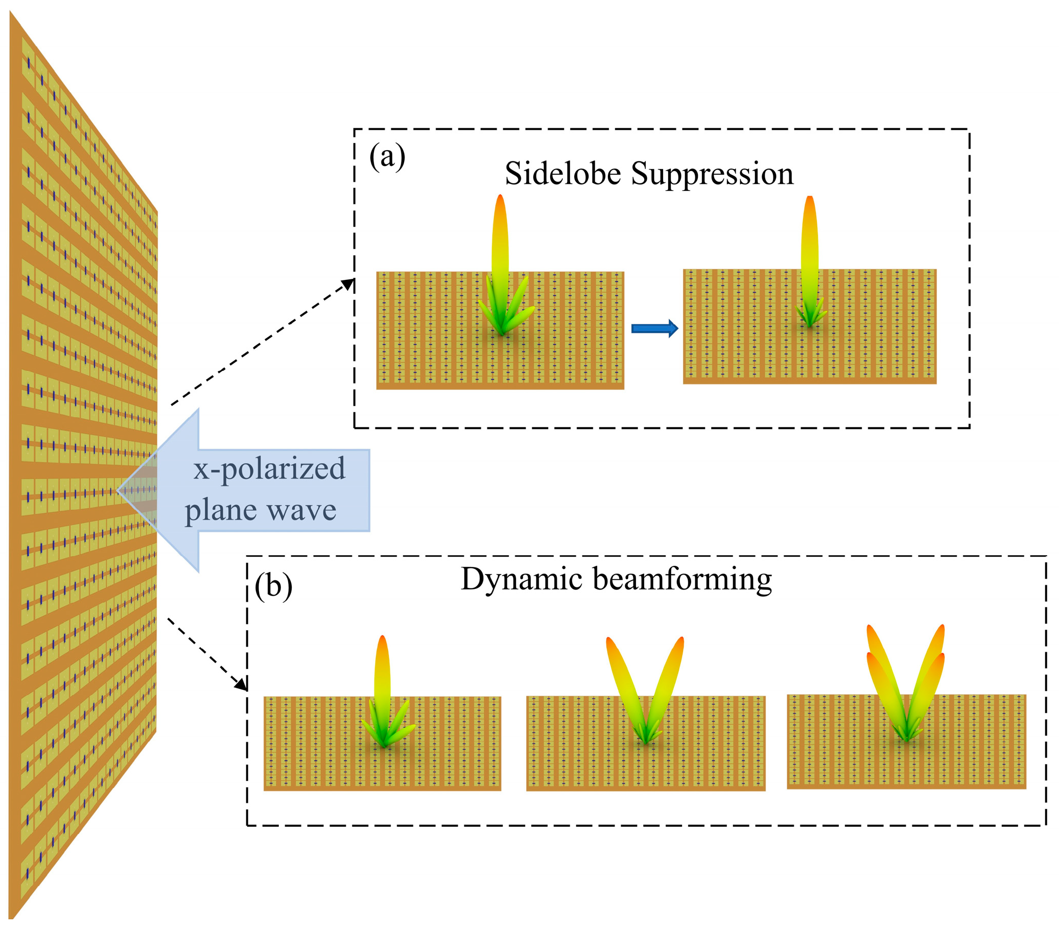
2.1. Design Principle

RAPM is a rectangular array comprising multiple reconfigurable unit elements, with M rows in the x direction and N rows in the y direction. When a plane wave with normal incidence is directed towards RAPM, its far-field pattern F (θ, ϕ) can be expressed as follows [23]:
F θ , ϕ = m = 1 M n = 1 N A ( m , n ) e i k p ( m 1 / 2 ) sin θ cos ϕ + k p ( n 1 / 2 ) sin θ sin ϕ + φ m , n
where the unit element’s period length in the x and y directions is represented by p. The unit element’s row number and column number are denoted by m and n, respectively. A (m, n) and φ (m, n) refer to the reflection amplitude and phase of the unit element numbered [m, n], respectively. For RAPM, A (m, n) can be continuously tuned from 0.02 to 0.98. Binary elements are utilized to represent opposite phases, with phase code “0” denoting φ (m, n) = 0 and phase code “1” indicating that φ (m, n) = π. The direction of the scattered beam is described by the elevation angle θ and azimuth angle ϕ. k is the wavenumber in free space.

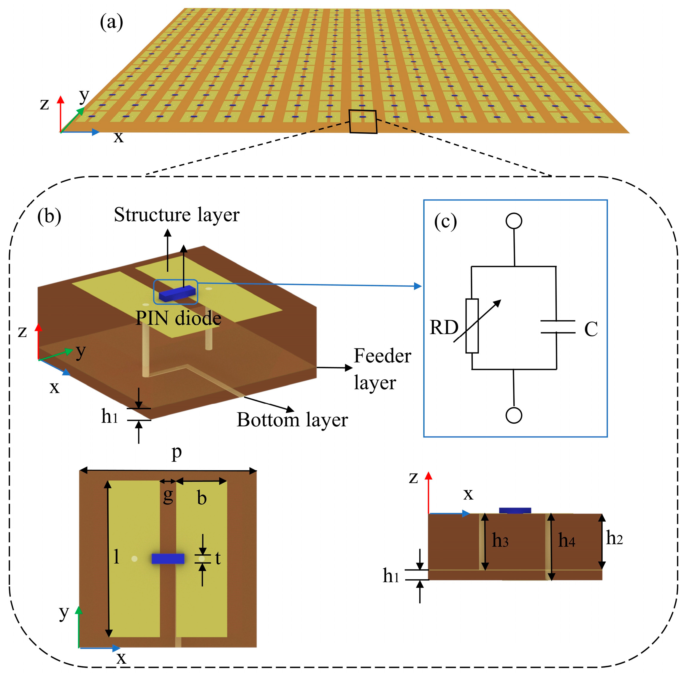
2.2. Design of Metasurfaces

As shown in Figure 1a,b, when a vertically x-polarized plane wave illuminates the RAPM, it enables the attainment of dynamic beamforming and sidelobe suppression. Figure 2a depicts the layout of RAPM. For the sake of clarity, the structural schematic of a single unit element is shown in Figure 2b. The period of the unit element in both the x and y directions is p = 8.7 mm. The metal layers of the unit element consist of a top structure layer loaded with one PIN diode, a feeder layer, and a bottom layer. All the metal structures are pure copper, and the thickness of metal layers is 0.018 mm. The top metal layer is composed of two parallel metal strips with a width of b = 2.5 mm. A PIN diode is embedded in the gap (g = 1.2 mm) between two metal strips. There are two through-holes on the feeder layer, one connected to the feeder layer, and the other connected to the bottom layer through the hole. The bottom layer can feed each unit element independently. The brown parts in Figure 2c are the dielectric layers made of F4B (εr = 2.2, tanδ = 0.002) sandwiched between the metal layers, with a thickness of h1 = 0.5 mm and h2 = 2.8 mm, respectively. Detailed geometric dimensions are provided as follows: l = 7.7 mm, t = 0.3 mm, h3 = 2.82 mm, h4 = 3.34 mm.
The Skyworks SMP1321−040LF [24], manufactured by Skyworks Technology Company, comprises the PIN diodes loaded in RAPM. Figure 2c displays the equivalent circuit model of this diode, consisting of a fixed capacitor (C = 0.15 pF) in parallel with a variable resistor (RD = 1–10,000 Ω), in which resistor resistance is roughly directly proportional to the feeding bias voltage.
For a PIN diode, its analytical expression of I–V curve can be deduced using the Shockley equation:
I D = I S ( e v / n T T 1 )
where ID refers to the forward current, IS stands for reverse saturation current, n denotes the ideal factor, and VT represents thermal voltage. Additionally, we can establish a relationship between the variable V (bias voltage) and RD (resistor resistance):
R D = V I S ( e V / n V T 1 )
For convenience and feasibility, we adopt resistor resistance (RD) in the simulation and voltage value (V) in the experiment for the PIN diode integrated into RAPM.

3. Results

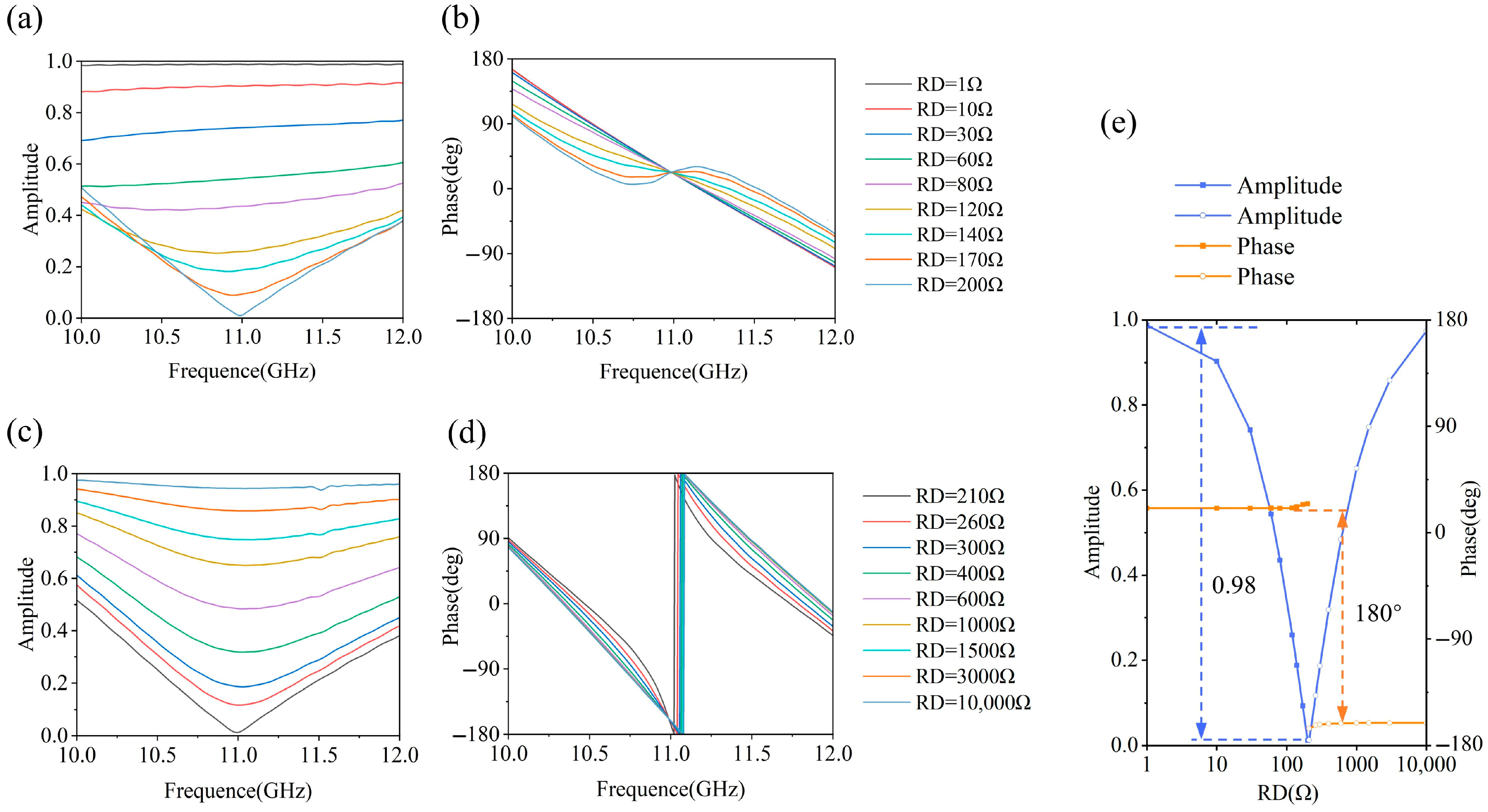
3.1. Simulation Results of Unit Element

To analyze the amplitude and phase responses of the unit element, full-wave EM simulations were conducted. It is worth noting that the PIN diode model was replaced with the equivalent circuit model shown in Figure 2c. Thus, the resistance of the variable resistor can be utilized to represent the bias voltage. Finally, the simulated S11s were obtained for different resistor resistances (RD = 1–10,000 Ω) within the frequency range of 8–13 GHz, under a “unit cell” boundary condition and with a normally incident x-polarized plane wave.
Figure 3 shows the simulation results of the unit element in the 10–12 GHz frequency band. As shown in Figure 3a, the amplitude response of the unit element gradually decreases as the resistance increases in the range of 1–200 Ω, while Figure 3c shows the opposite trend as the resistance increases in the range of 210–10,000 Ω. Furthermore, Figure 3b,d demonstrate that the reflection phase difference between unit elements encoded by different phase codes is approximately 180°. The unit element operates most effectively at 11 GHz. In addition, Figure 3e shows the reflection amplitude continuously decreases from 0.98 to 0.02, as the resistance gradually increases from 1 Ω to 200 Ω, and the reflection phase remains unchanged at φ (m, n) = 0 (phase code is 0). In contrast, as the resistance progressively grows from 210 Ω to 10,000 Ω, the reflection amplitude increases from 0.02 to 0.98, and the reflection phase remains unchanged at φ (m, n) = π (phase code is 1). It is observed that the unit element has excellent performance in adjusting the reflection phase switch between two opposite states and the continuously regulating the reflection amplitude from 0.02 to 0.98 without interference.
Over the frequency band of 10.5–11.5 GHz, the reflection phase of the unit elements can be switched between two states with 180° ± 40° phase difference. In addition, the reflection amplitude can be continuously tuned from 0.15 to 0.95. Hence, the frequency band from 10.5 to 11.5 GHz is defined as the operating band of RAPM.
In the experiment, variable V (bias voltage) is in the range of 0–0.85 V in Equations (2) and (3). Noticeably, the reflection phase is switched with about 180° phase difference when the bias voltage is 0.65 V.

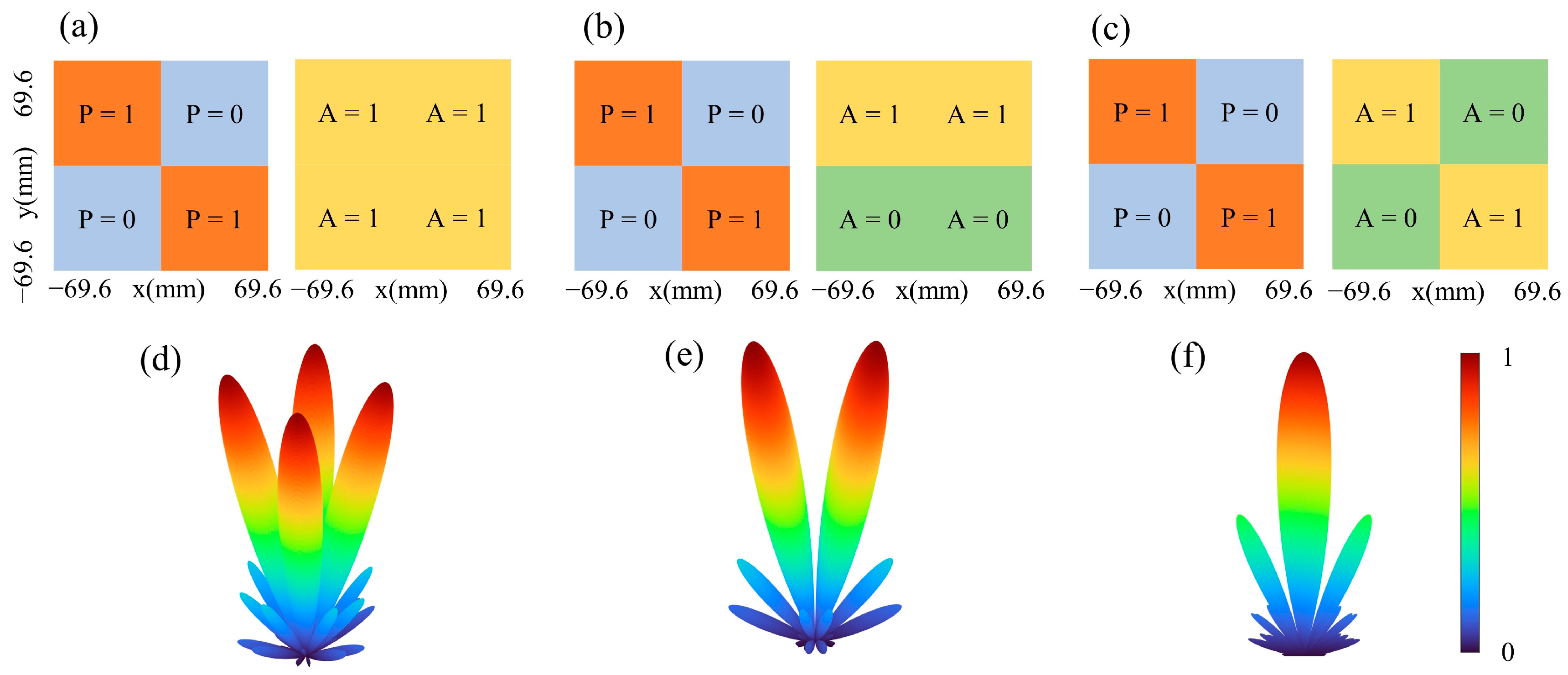
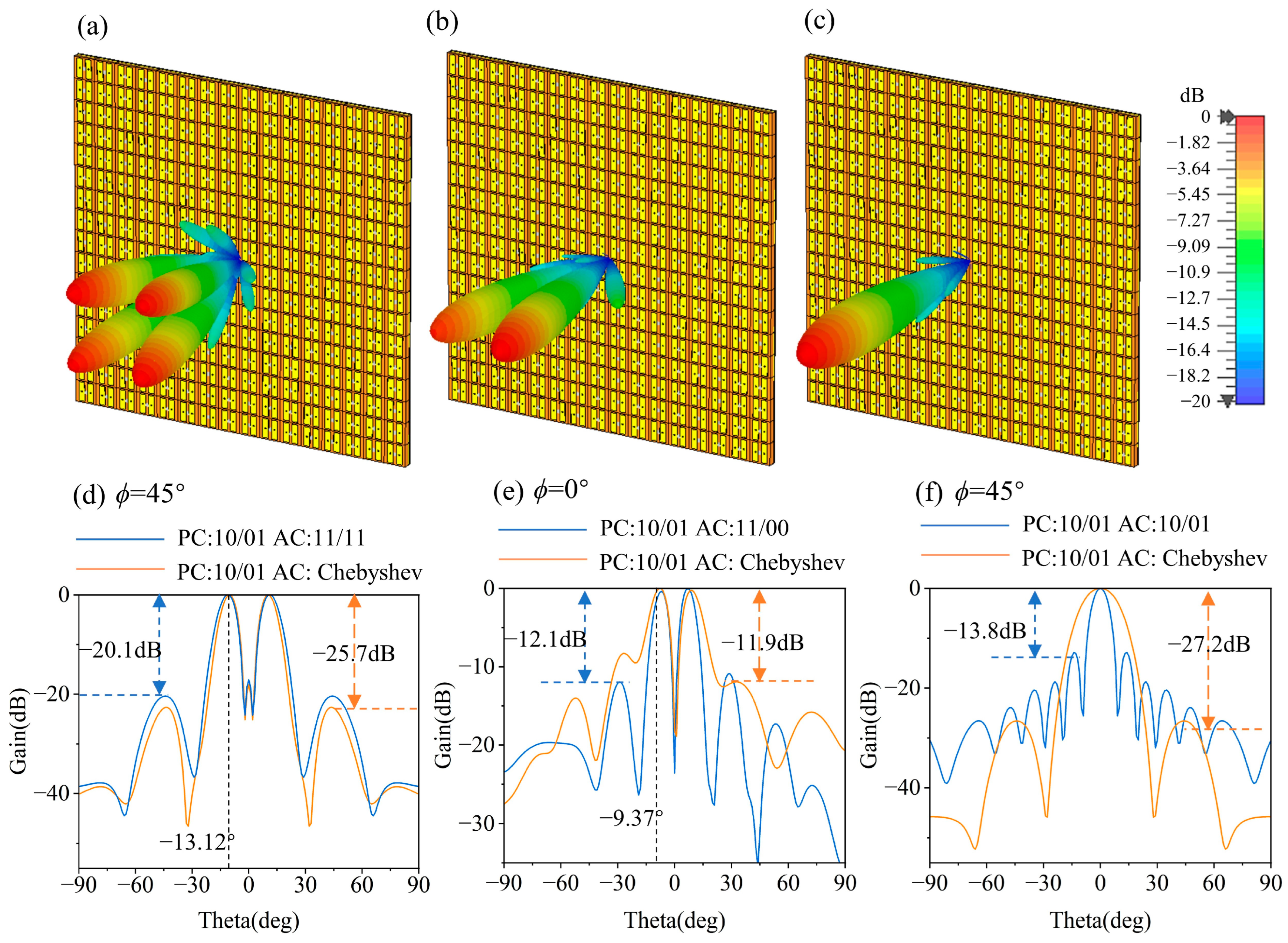
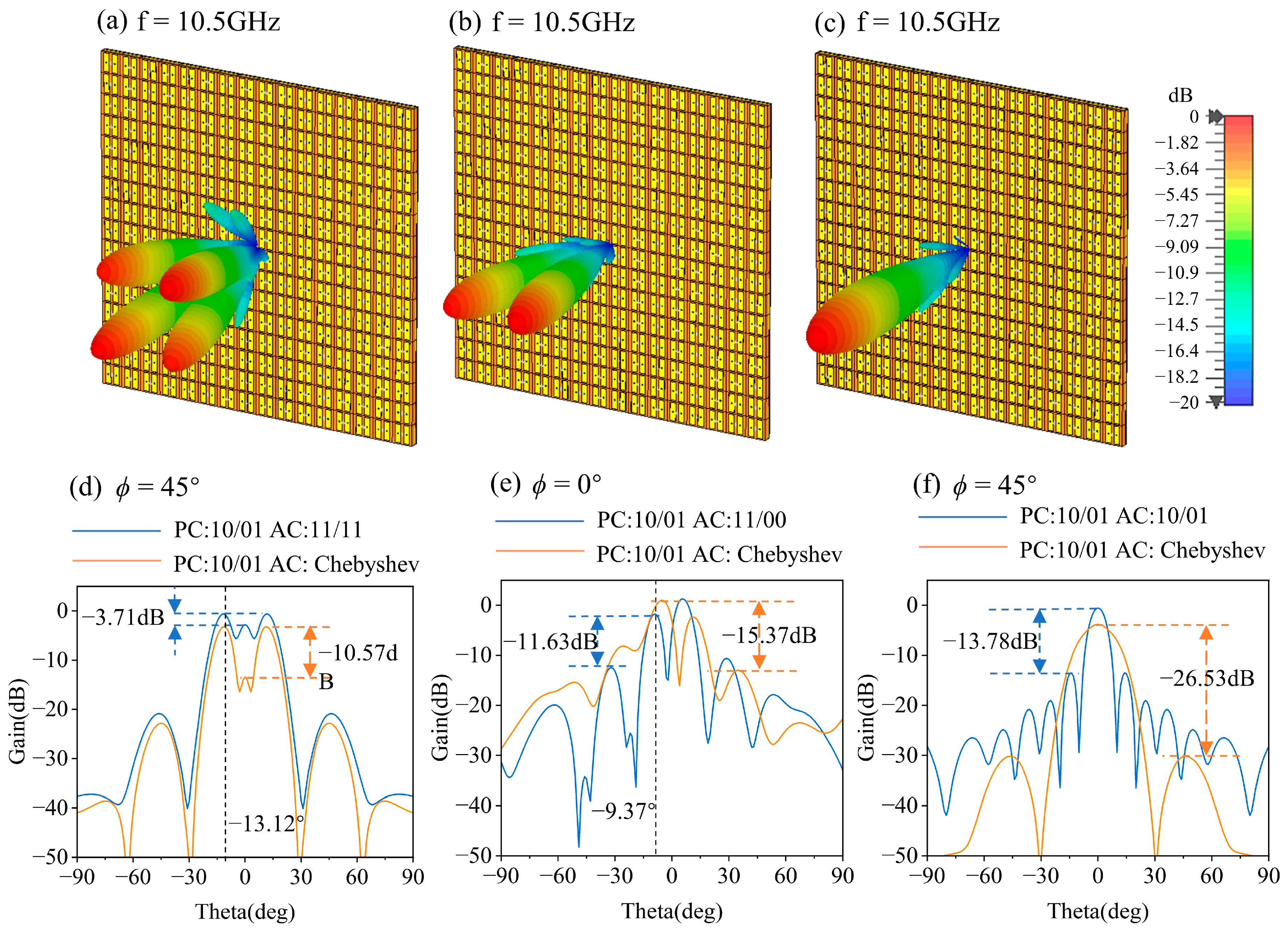
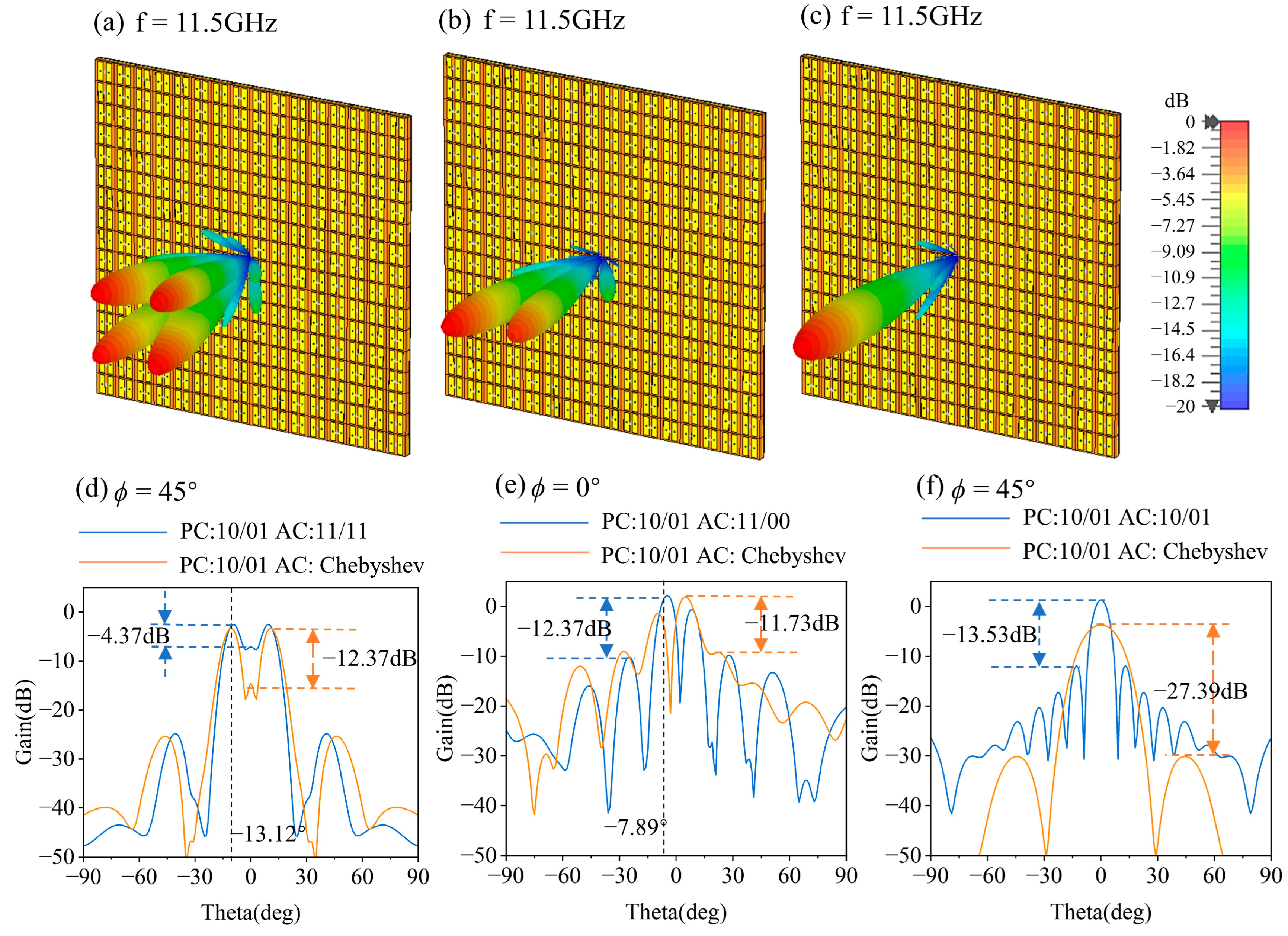
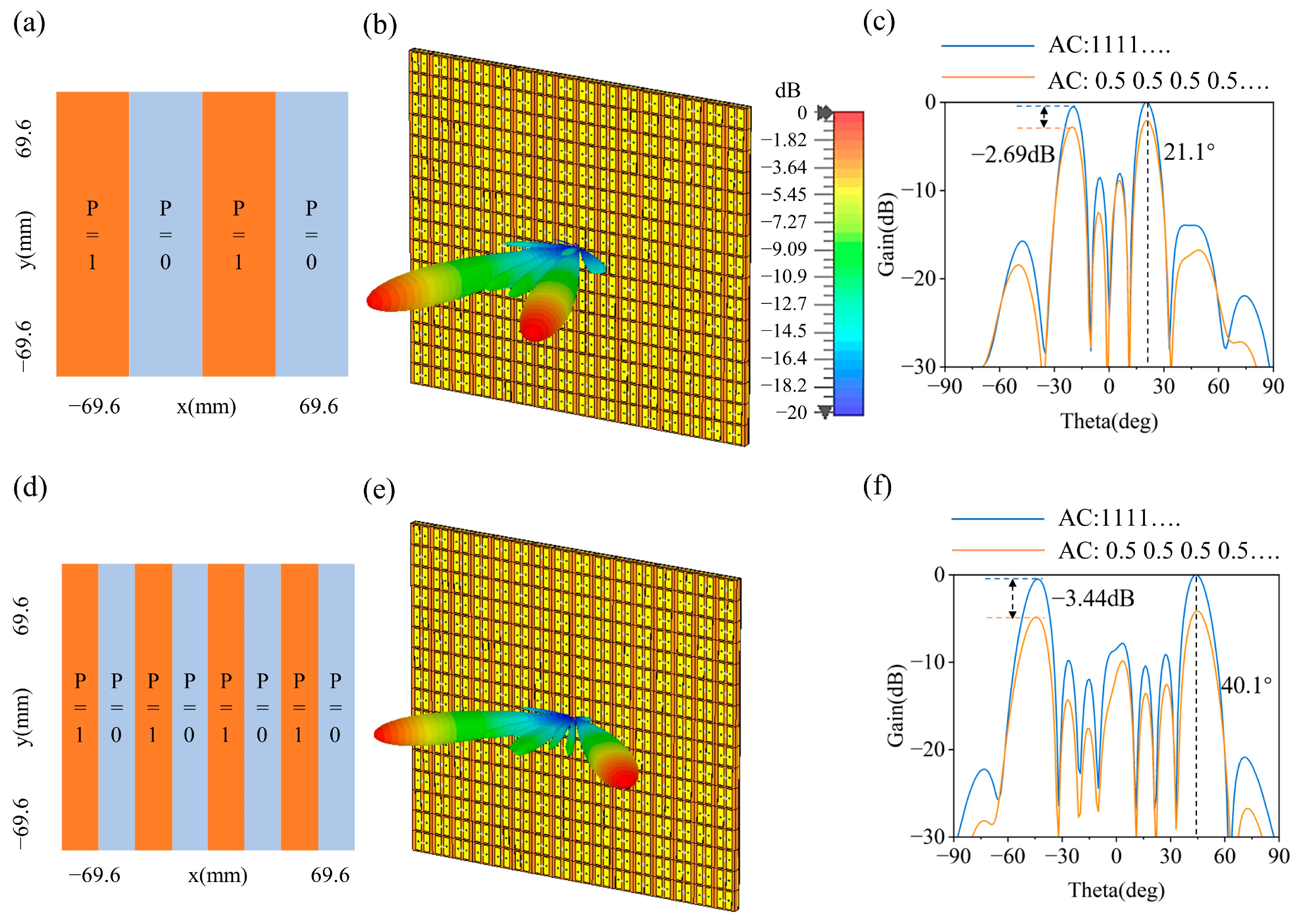
3.2. Simulation Results of RAPM

According to Equation (1), it is noteworthy that A (m, n) and φ (m, n) play crucial roles in manipulating the energy intensity and direction of reflected EM beams, which can be dynamically adjusted in real time. The initial maximal value of F (θ, ϕ) can be achieved when θ and ϕ satisfy the following equations [25]:
φ = ± arctan Γ x Γ y , φ = π ± arctan Γ x Γ y
θ = arctan λ 1 Γ x 2 + 1 Γ y 2
In a 1-bit phase-coding metasurface, Γx and Γy represent the minimum physical cycle length of the same phase in the x direction and y direction, respectively [23].
In particular, if the phase-coding sequence gradient changes to Γx → ∞ or Γy → ∞, the unit elements phase distribution in RAPM is analogous to a piano keyboard, and the equation of θ can be simplified as follows:
θ = arctan ( λ Γ )
Obviously, θ is governed by λ and Γ.
Consequently, the quantity, energy distribution, and scattered deflection of EM beams can be accurately modified by calculating the amplitude-phase codes of RAPM.
RAPM consists of 16 × 16 unit elements, occupying an area of 139.2 × 139.2 mm2. In conformity with the expertise of reconfigurable coding metasurfaces, RAPM can independently and concurrently implement 1-bit phase codes and multi-bit amplitude codes. Similar to reflection phase codes, non-reflecting and fully reflecting unit elements can be encoded as amplitude codes 0 and 1, respectively. The normalization of the reflection amplitude is carried out to facilitate the description of the amplitude- and phase-coding sequences of metasurface in subsequent articles.
The coupling between different unit elements diminishes the periodic boundary conditions, which leads to additional damage to the EM response. To mitigate this phenomenon, we introduce the concept of the superunit for designing the phase and amplitude codes. RAPM is composed of 2 × 2 superunits, which have a size of 69.6 × 69.6 mm2. Therefore, in Equation (4), Γx = Γy = 69.6 mm, equivalent to 2.55 times the ideal operating wavelength. Figure 4 illustrates the results of the metasurface far-field radiation patterns computed in MATLAB R2021a software with different phase amplitude codes. In Figure 4a–c, three metasurfaces whose phase-coding sequences of the superunit are 10/01 identically, but their amplitude-coding sequences are different. The metasurface with the amplitude-coding sequences of 11/11, 11/00, and 10/01 are named A1, A2, and A3, respectively. By employing a feeding system at the edges of RAPM, we can modulate the amplitude and phase responses of each superunit.
Under the condition of a vertically illuminating x-polarized plane wave from the -z direction on RAPM, we calculated and plotted the reflected pattern of A1, A2, and A3 using Equation (1) in MATLAB R2021a software. Figure 4d–f show that the far-field radiation pattern of RAPM with different amplitude-phase codes were calculated at 11 GHz, generating 4, 2, or 1 scattered beam(s), respectively. It follows that the amplitude codes of the metasurface also affects the quantity and direction of reflected EM beams when the phase codes are consistent.
We used CST 2022 to conduct full-wave simulations of RAPM, configuring the far-field monitors from 10 GHz to 12 GHz with 0.1 GHz steps. In Figure 5, Figure 6 and Figure 7, the 3-D far-field radiation patterns describe the power density of the reflected EM waves, and the line graphs are obtained by normalizing the radiated power of the 2-D far-field radiation pattern.
RAPM displays optimal performance at 11 GHz, which aligns with the unit element. Figure 5 shows the 3-D and 2-D far-field radiation patterns obtained in CST 2022 for different encoded metasurfaces at the optimal operating frequency of 11 GHz. As for A1, all the unit elements possess an amplitude code of 1. A1 manipulates EM waves similarly to a metasurface whose reflection phase difference is 180° with a chessboard arrangement. As shown in Figure 4d and Figure 5a, the reflected waves are divided into four lobes on average in 2-D spaces. Consequently, according to Equations (4) and (5), Γx = Γy = 8p; ϕ = 45°, 135°, 225°, and 315°; and θ = 15.48°. Figure 5d displays that the sidelobe suppression level (SLL) of the reflected beams is −19.61 dB. In contrast, A2 features the amplitude-coding sequence of 11/00. In this case, the phase-coding sequences can be considered as 10 in the x direction. A2 manipulates EM waves similarly to the metasurface whose reflection phase difference is 180° with a piano keyboard arrangement. The reflected waves are divided into two lobes on average in the x direction, as shown in Figure 4e and Figure 5b. Therefore, Γx = 8p, Γy → ∞, and θ = 11.08° can be reasonably calculated. Figure 5e displays the SLL of the reflected beams is −11.85 dB. Lastly, A3 employs an amplitude-coding sequence of 10/01. In this case, superunits whose amplitude code is encoded by “0” cannot play the role of phase regulation. The phase-coding sequences are transformed to “11” in a cross section of ϕ = 45°. A3 manipulates EM waves similarly to a fully reflective metasurface without reflection phase differences among unit elements. There is only one scattered beam with an elevation angle θ = 0° and an azimuth angle ϕ = 0° lying along the z axis, as shown in Figure 4f and Figure 5c. Figure 5f displays that the SLL of the reflected beams is −12.27 dB. It can be observed that the simulation results in CST 2022 correspond favorably to the analytical predictions in MATLAB R2021a software, validating the accuracy of the above calculation method.
Furthermore, the optimization of the distributions of reflected energy can be achieved by redesigning the amplitude codes of the metasurface. To attain low SLL for the reflected beams, the amplitude codes were no longer laid out with a superunit as a whole. The amplitude codes encoded as 0 remained unchanged, whereas the amplitude codes encoded as 1 complied with the Chebyshev distribution. The optimized metasurfaces are referred to as C1, C2, and C3, respectively, corresponding to those named A1, A2, and A3. Notably, Figure 5d–f depicts the apparent sidelobe suppression effectiveness of optimized metasurfaces. Compared with A1, the SSL of C1 decreases from −19.61 dB to −24.57 dB. Similarly, the SSL of C2 decreases from −11.85 dB to −11.90 dB. In particular, the conspicuously reduced SSL for C3 decreases from −12.27 dB to −29.27 dB. In summary, optimizing the amplitude codes suppressed the beams’ sidelobe and retained the impregnability of the elevation angle θ and azimuth angle ϕ of the scattered beams.
RAPM operates over a widely defined operating band ranging from 10.5 to 11.5 GHz. Similarly, Figure 6 and Figure 7 show the 3-D and 2-D far-field radiation patterns obtained in CST 2022 for different encoded metasurfaces at 10.5 GHz and 11.5 GHz, respectively, thus showing the worst situation of EM beams’ regulation within the defined operating frequency band. Figure 6a–c demonstrates the 3-D far-field radiation patterns of A1, A2, and A3 at 10.5 GHz, and the 2-D far-field radiation patterns of RAPM are illustrated in Figure 6d–f at the cut angles of ϕ = 45°, ϕ = 0°, and ϕ = 45°, respectively. The blue lines show the results with uniform amplitude-coding sequences, while the orange lines show the results with optimized ones. Figure 7 illustrates the 3-D and 2-D simulation results of RAPM at 11.5 GHz in a similar way. In the operating frequency band, the elevation angle θ, azimuth angle ϕ, and the energy intensity of the reflected beams remain basically stable. For A1, the energy of the reflected EM waves is evenly distributed among the four beams on average. Notably, the SSL of the beams can only achieve a value below −3.71 dB. Nevertheless, after optimizing the amplitude codes, the SSL of the beams would remain below −10.57 dB. Next, A2 exhibits uneven energy distribution (−4.30 dB in the worst case) between two lobes when the operating frequency shifts from 11 GHz and the SLL of beams is below −11.63 GHz. After optimization, the uneven energy distribution and the SLL of beams would remain below −3.72 dB and −11.37 dB, respectively. In contrast, A3 and C3 are not significantly affected by the operating frequency shift, and their SLL of beams can remain below −26.53 dB. In general, the ability of RAPM to manipulate EM waves remains excellent over the defined operating band.
For further exploration of the beamforming mechanism, we redesigned the amplitude and phase-coding sequence of the metasurface and achieved more complex multi-beamforming. At the beginning, the amplitude coeds of superunits were encoded as 1. And then, we designed the phase-coding sequences according to Equation (1). Figure 8 shows the simulated 3-D radiation patterns of metasurfaces with different phase codes. Metasurfaces with different coding sequences can flexibly adjust the deflection angle of the reflected beams. In Figure 8a, the phase-coding sequence is 11110000.../11110000.... According to Equations (4) and (6), Γx = 4p, Γy → ∞, ϕ = 0° and θ = 21.39° can be reasonably calculated, respectively. Similarly, in Figure 8d, the phase-coding sequence is 1100.../1100..., so Γx = 2p, Γy → ∞. The azimuth angle ϕ and elevation angle θ of EM beams are 0° and 38.08°.
Figure 8b,e show the 3-D far-field radiation pattern of the reflected beams with different deflection angles. On the basis of the above phase-coding sequences, the amplitude sequence of the metasurface can be further encoded to realize the redistribution of EM waves’ energy. When the amplitude is synchronized, the codes vary within the range of 0.02–0.98 in order to regulate the energy intensity of the reflected beams. The energy intensity of the reflected beam can be adjusted by consistently varying the amplitude encoding in the range of 0.02 to 0.98. Additionally, optimizing the amplitude codes with the Chebyshev distribution allows for the suppression of the sidelobes of beams. As shown in Figure 8c,f, when the phase code of the unit element is unchanged and the amplitude code is collectively adjusted to 0.5, the energy intensity of the reflected beams is reduced by about 3 dB. In short, with different amplitude-phase-coding sequences, our proposed metasurface can realize the formation of diverse reflected EM beams and flexibly manipulate EM waves in 2-D space.

4. Discussion

Within this manuscript, we have introduced an innovative and adaptive amplitude-phase-coding metasurface, which aimed to facilitate the distribution of EM waves’ energy and the manipulation of wavefronts.
The preceding research works [20,21,22], as well as our proposed RAPM, achieved dynamic-control-reflected EM beams by incorporating active diodes integrated within the upper passive metal layer. The differences between our study and the previous works [20,21,22] in the structures and performance are shown in Table 1. RAPM operates normally in the 10.5–11.5 GHz band, basically covering the 11 GHz band in microwave communication systems. Therefore, it has broad development prospects in the field of large information transmission capacity and wireless communication. Next, our proposed metasurface has a simplified upper metal layer, which has only one diode loaded in a unit element. Although the reflection phase of the unit element can only switch between two opposite states, its reflection amplitude can be adjusted continuously from 0.02 to 0.98 with the maximum degree of freedom. And most importantly, compared with previous works, our research showcases exceptional performance in terms of device miniaturization. A diminutive-scale metasurface is composed of a mere 16 × 16 unit elements, which attains a high level of flexibility in modulating the reflected EM waves. Device miniaturization not only reduces the complexity and expense of fabrication but also unveils more possibilities for the expandability and commercial viability of reconfigurable coding metasurfaces. Notably, each unit element of RAPM has an independent feeder wire, so the unit element can be encoded independently without being affected by neighboring one, which greatly improves the freedom of the metasurface to regulate the reflected EM waves.
Subsequently, a comparative analysis is conducted in order to compare the ability of the metasurfaces mentioned above. The metasurface proposed in [20] has the ability to regulate the quantities of reflected EM beams in 1-D space, while the distribution of EM waves’ energy is limited. The proposed metasurface in [21] can divide the vertically incident waves into two lobes with distinct elevation angles (θ) and power intensities. Regarding the metasurface described in [22], it is able to modulate the quantities of reflected EM beams in 1-D space, including the suppression of the sidelobes of the scattering beam. It is worth noting that our proposed metasurface achieves independent multi-bit amplitude coding and 1-bit phase coding. Moreover, both codes’ schemes can be dynamically reprogrammed across a wide frequency range. Additionally, the metasurface demonstrates the ability to modulate the quantities and direction of reflected EM beams in 2-D space using a 1-bit phase-coding sequence. Furthermore, by employing multi-bit amplitude codes, for any possible quantities of reflected EM beams, RAPM effectively suppresses beams sidelobes and adjusts the energy intensity of the beams. Upon comparing our research with those of previous works, RAPM demonstrates unique beam-regulation capability in 2-D space by controlling the bias voltage of PIN diodes with a unit-element-independent feeder wire. In particular, our proposed metasurface can achieve flexible control of EM beams with fewer unit elements.
Reconfigurable metasurfaces have practical possibilities in the field of wireless communication. For example, our metasurface can assist the signal base station in the network signal supplementary coverage. For areas where the signal radiated cannot be effectively covered, RAPM may be used to assist in achieving high power and complete coverage of network signals. The specific working process is shown in Figure 9. The metasurface receives EM waves carrying information from the signal base station or horn antenna feed source and then reflects EM waves to the mobile terminal according to the actual situation so that the terminal device can receive high-power network signals.
However, RAPM still has certain limitations. Due to the axisymmetric structure of the top metal layer in the unit element, it can only operate effectively when the incident wave is polarized in the x direction. To apply it in more complex electromagnetic environments, it may in fact demonstrate even greater potency to optimize the structure of the top metal layer in the unit element, such as a more centrally symmetric configuration.

5. Conclusions

In conclusion, we have proposed a novel reconfigurable coding metasurface whose unit elements can achieve the dynamic and independent regulation of amplitude and phase response. The unit element comprises an active device and passive structures whose EM response could be controlled by the bias voltages applied across the PIN diodes. Through the utilization of metal vias and the bottom metal layer, the RAPM has enhanced the potential for beam control in a 2-D space. The RAPM consists of 16 × 16 unit elements, occupying an area of 139.2 × 139.2 mm2, which exhibits a features a miniaturized array scale. Through designing its coding sequences, the quantity, elevation angle θ, azimuth angle ϕ, and the SLL of reflected waves can be modulated in real time within the frequency band of 10.5–11.5 GHz. Compared to traditional phase-coding or amplitude-coding metasurfaces, RAPM exhibits more powerful capabilities to achieve multifunctional EM manipulation. This provides exciting possibilities for developing novel smart EM devices and robust systems in radar and communication.

Author Contributions

Conceptualization, L.G. and H.Z.; methodology, Y.Z.; data curation, P.Z. and J.L.; writing—original draft preparation, L.G. and. Y.Z.; writing—review and editing, Z.H.; visualization, Z.X. and Y.C.; funding acquisition, L.G. All authors have read and agreed to the published version of the manuscript.

Funding

This research received no external funding.

Data Availability Statement

The data presented in this study are available from the corresponding author upon reasonable request.

Conflicts of Interest

The authors declare no conflict of interest.

References

  1. Li, Y.; Chen, J. Design of Miniaturized High Gain Bow-Tie Antenna. IEEE Trans. Antennas Propag. 2022, 70, 738–743. [Google Scholar] [CrossRef]
  2. Liu, L.; Zhang, X.; Kenney, M.; Su, X.; Xu, N.; Ouyang, C.; Shi, Y.; Han, J.; Zhang, W.; Zhang, S. Broadband Metasurfaces with Simultaneous Control of Phase and Amplitude. Adv. Mater. 2014, 26, 5031–5036. [Google Scholar] [CrossRef]
  3. Yu, N.; Capasso, F. Flat optics with designer metasurfaces. Nat. Mater. 2014, 13, 139–150. [Google Scholar] [CrossRef] [PubMed]
  4. Luo, X. Subwavelength optical engineering with metasurface waves. Adv. Opt. Mater. 2018, 6, 1701201. [Google Scholar]
  5. Zhang, T.; Pang, X.; Zhang, H.; Zheng, Q. Ultrabroadband RCS Reduction and Gain Enhancement of Patch Antennas by Phase Gradient Metasurfaces. IEEE Antennas Wirel. Propag. Lett. 2023, 22, 665–669. [Google Scholar] [CrossRef]
  6. Zhang, K.; Wang, Y.; Burokur, S.N.; Wu, Q. Generating Dual-Polarized Vortex Beam by Detour Phase: From Phase Gradient Metasurfaces to Metagratings. IEEE Trans. Microw. Theory Tech. 2022, 70, 200–209. [Google Scholar] [CrossRef]
  7. Liu, S.; Cui, T.J.; Xu, Q.; Bao, D.; Du, L.; Wan, X.; Tang, W.X.; Ouyang, C.; Zhou, X.Y.; Yuan, H.; et al. Anisotropic coding metamaterials and their powerful manipulation of differently polarized terahertz waves. Light Sci. Appl. 2016, 5, e16076. [Google Scholar] [CrossRef]
  8. Yan, L.; Zhu, W.; Karim, M.F.; Cai, H.; Gu, A.Y.; Shen, Z.; Chong, P.H.J.; Tsai, D.P.; Kwong, D.-L.; Qiu, C.-W.; et al. Arbitrary and Independent Polarization Control In Situ via a Single Metasurface. Adv. Opt. Mater. 2018, 6, 1800728. [Google Scholar] [CrossRef]
  9. Mu, Y.; Qi, J.; Xia, S.; Li, L.; Sihvola, A. Non-Interleaved Bilayer Complex-Amplitude Janus Metasurface Enabling Energy-Tailorable Bidirectional Wave Modulation. Laser Photonics Rev. 2023, 17, 2200659. [Google Scholar] [CrossRef]
  10. Tan, X.; Chen, J.; Li, J.; Yan, S. Water-based metasurface with continuously tunable reflection amplitude. Opt. Express 2022, 30, 6991–6998. [Google Scholar] [CrossRef]
  11. Yu, N.; Genevet, P.; Kats, M.A.; Aieta, F.; Tetienne, J.-P.; Capasso, F.; Gaburro, Z. Light Propagation with Phase Discontinuities: Generalized Laws of Reflection and Refraction. Science 2011, 334, 333–337. [Google Scholar] [CrossRef] [PubMed]
  12. Cui, T.J.; Qi, M.Q.; Wan, X.; Zhao, J.; Cheng, Q. Coding metamaterials, digital metamaterials and programmable metamaterials. Light Sci. Appl. 2014, 3, e218. [Google Scholar] [CrossRef]
  13. Huang, C.; Yang, J.; Wu, X.; Song, J.; Pu, M.; Wang, C.; Luo, X. Reconfigurable Metasurface Cloak for Dynamical Electromagnetic Illusions. ACS Photonics 2018, 5, 1718–1725. [Google Scholar] [CrossRef]
  14. Yang, J.; Ke, J.C.; Chen, M.; Chen, M.Z.; Dai, J.Y.; Chen, J.F.; Yang, R.; Wu, J.W.; Cheng, Q.; Cui, T.J. Control of the harmonic near-field distributions by an active metasurface loaded with pin diodes. Photon. Res. 2021, 9, 344–350. [Google Scholar] [CrossRef]
  15. Ma, Q.; Hong, Q.R.; Bai, G.D.; Jing, H.B.; Wu, R.Y.; Bao, L.; Cheng, Q.; Cui, T.J. Editing Arbitrarily Linear Polarizations Using Programmable Metasurface. Phys. Rev. Appl. 2020, 13, 021003. [Google Scholar] [CrossRef]
  16. Zhang, N.; Chen, K.; Zheng, Y.; Hu, Q.; Qu, K.; Zhao, J.; Wang, J.; Feng, Y. Programmable Coding Metasurface for Dual-Band Independent Real-Time Beam Control. IEEE J. Emerg. Sel. Top. Circuits Syst. 2020, 10, 20–28. [Google Scholar] [CrossRef]
  17. Huang, C.; Zhang, C.; Yang, J.; Sun, B.; Zhao, B.; Luo, X. Reconfigurable Metasurface for Multifunctional Control of Electromagnetic Waves. Adv. Opt. Mater. 2017, 5, 1700485. [Google Scholar] [CrossRef]
  18. Yang, J.; Chen, J.; Quan, L.; Chen, X.; Shi, H.; Liu, Y.; Xue, W. Flexible beamforming using transmission-type coding metasurface. J. Phys. D Appl. Phys. 2022, 55, 345006. [Google Scholar] [CrossRef]
  19. Wang, H.L.; Ma, H.F.; Chen, M.; Sun, S.; Cui, T.J. A Reconfigurable Multifunctional Metasurface for Full-Space Control of Electromagnetic Waves. Adv. Funct. Mater. 2021, 31, 2100275. [Google Scholar] [CrossRef]
  20. Liao, J.; Guo, S.; Yuan, L.; Ji, C.; Huang, C.; Luo, X. Independent Manipulation of Reflection Amplitude and Phase by a Single-Layer Reconfigurable Metasurface. Adv. Opt. Mater. 2022, 10, 2101551. [Google Scholar] [CrossRef]
  21. Liang, J.C.; Zhang, L.; Cheng, Z.W.; Zhang, P.; Cui, T.J. Flexible Beam Manipulations by Reconfigurable Intelligent Surface with Independent Control of Amplitude and Phase. Front. Mater. 2022, 9, 946163. [Google Scholar] [CrossRef]
  22. Wang, H.L.; Zhang, Y.K.; Zhang, T.Y.; Ma, H.F.; Cui, T.J. Broadband and Programmable Amplitude-Phase-Joint-Coding Information Metasurface. ACS Appl. Mater. Interfaces 2022, 14, 29431–29440. [Google Scholar] [CrossRef] [PubMed]
  23. Zhang, X.G.; Tang, W.X.; Jiang, W.X.; Bai, G.D.; Tang, J.; Bai, L.; Qiu, C.-W.; Cui, T.J. Light-Controllable Digital Coding Metasurfaces. Adv. Sci. 2018, 5, 1801028. [Google Scholar] [CrossRef] [PubMed]
  24. Low Capacitance, Plastic Packaged PIN Diodes. Available online: https://www.skyworksinc.com/zh-CN/Products/Diodes/SMP1321-Series (accessed on 2 November 2023).
  25. Li, W.; Qiu, T.; Wang, J.; Zheng, L.; Jing, Y.; Jia, Y.; Wang, H.; Han, Y.; Qu, S. Programmable Coding Metasurface Reflector for Reconfigurable Multibeam Antenna Application. IEEE Trans. Antennas Propag. 2021, 69, 296–301. [Google Scholar] [CrossRef]
Figure 1. Functional of RAPM. (a) Dynamic multibeam-forming ability of RAPM; (b) sidelobe-suppression ability of RAPM.
Electronics 12 04565 g001
Figure 2. Structural schematics of RAPM and its unit elements. (a) Schematic of RAPM; (b) structural schematic of a unit element; (c) the equivalent circuit of the PIN diode load in the unit element.
Electronics 12 04565 g002
Figure 3. The amplitude and phase responses of the proposed unit element. (ad) Simulated amplitude and phase responses of the unit element with different RDs from 10 to 12 GHz; (e) simulated amplitude and phase responses of the unit element with different RDs at 11 GHz.
Electronics 12 04565 g003
Figure 4. (ac) Phase and amplitude-coding sequences of metasurfaces named A1, A2, and A3; (df) simulated far-field radiation pattern of A1, A2, and A3 in MATLAB R2021a software at 11 GHz (The beams energy intensity is normalized).
Electronics 12 04565 g004
Figure 5. (ac) Simulated 3-D far-field radiation pattern of A1, A2, and A3 in CST 2022 at 11 GHz; (df) simulated 2-D far-field radiation patterns of RAPM in CST 2022 at 11 GHz, in which PC is the abbreviation of the phase-coding sequence and AC is the abbreviation of the amplitude-coding sequence.
Electronics 12 04565 g005
Figure 6. (ac) Simulated 3-D far-field radiation pattern of A1, A2, and A3 at 10.5 GHz; (df) simulated 2-D far-field radiation patterns of RAPM at 10.5 GHz.
Electronics 12 04565 g006
Figure 7. (ac) Simulated 3-D far-field radiation pattern of A1, A2, and A3 at 11.5 GHz; (df) simulated 2-D far-field radiation patterns of RAPM at 11.5 GHz.
Electronics 12 04565 g007
Figure 8. (a,d) Different phase-coding sequences of metasurfaces; (b,e) simulated 3-D far-field radiation pattern with different phase-coding sequences; (c,f) simulated 2-D far-field radiation patterns with different phase-coding sequences.
Electronics 12 04565 g008
Figure 9. RAPM assists in network signal supplementary coverage.
Electronics 12 04565 g009
Table 1. The differences between our study and the previous works [20,21,22].
The Previous Worksf/GHzDiodes in One Unit ElementReflection Phase ResponsesReflection Amplitude ResponsesM × N Unit ElementsUnit Element Feeding Mode
[20]8PIN diode-1 and PIN diode-20°, 180°0.45, 0.9220 × 20Joint of
one column
[21]3A PIN diode and a varactor diode0°, 90°, 180°, 270°0.6, 0.8520 × 20Joint of
one column
[22]10A PIN diode0°, 180°0.02–0.9524 × 15Joint of
one column
Our works11A PIN diode0°, 180°0.02–0.9816 × 16Several
Disclaimer/Publisher’s Note: The statements, opinions and data contained in all publications are solely those of the individual author(s) and contributor(s) and not of MDPI and/or the editor(s). MDPI and/or the editor(s) disclaim responsibility for any injury to people or property resulting from any ideas, methods, instructions or products referred to in the content.

