Abstract
The use of robotic technologies for caregiving and assistance has become a very interesting research topic in the field of robotics. Towards this goal, the researchers at Politecnico di Torino are developing robotic solutions for indoor assistance. This paper presents the D.O.T. PAQUITOP project, which aims at developing a mobile robotic assistant for the hospital environment. The mobile robot is composed of a custom omnidirectional platform, named PAQUITOP, a commercial 6 dof robotic arm, sensors for monitoring vital signs in patients, and a tablet to interact with the patient. To prove the effectiveness of this solution, preliminary tests were conducted with success in the laboratories of Politecnico di Torino and, thanks to the collaboration with the Onlus Fondazione D.O.T. and the medical staff of Molinette Hospital in Turin (Italy), at the hematology ward of Molinette Hospital.
1. Introduction
In the last few decades, many researchers in the robotics field have addressed the theme of assistive robotics, developing several mobile robotic platforms conceived of to help weak or non-self-sufficient subjects [1]. On the one hand, an unprecedented decrease in fertility and mortality rates in industrialized countries have resulted in the widespread aging of the population. Such a phenomenon affects the daily lives of both individuals and the government or private organizations and motivates the search for solutions to the growing demand for health care, housing, caregiving, and social security [2,3]. On the other hand, the current pandemic emergency, caused by COVID-19, has highlighted the need to relieve human operators of many activities, especially in hospitals, geriatric wards, and hospices, where patients may be endangered by the closeness to other people [4]. Against this scenario, socially assistive robots (SARs) have recently been proposed as a possible solution for elderly care and monitoring in the domestic [5] and hospital [6] environments. Although the impact needs to be addressed from an ethical point of view, according to Abdi et al. [7], different robots for social assistance already exist. These studies often brought researchers to focus their study on human–machine interaction, realizing companion robots with humanoid [8] or pet-like architectures [9]. Such robots have been particularly studied concerning dementia, aging, and loneliness problems [10,11]. Different studies focus on detailed monitoring tasks, such as heat strokes [12] and fall detection [13]. In order to achieve these functionalities, many challenges must be faced. First of all, the robot needs to be able to navigate in a cluttered and unstructured environment, avoiding collisions with static and dynamic obstacles, and it should be able to deal with the presence of small obstacles, such as carpets and electric cables, which could be lying on the ground. To be able to effectively navigate in such environments and perform monitoring tasks, the robot’s platform must exhibit high mobility in the plane of motion and it must be provided with sensors and the computational capability to run autonomous navigation algorithms. Moreover, such systems must interact with the user through specifically conceived Human–Machine Interfaces (HMIs). For this reason, many HMIs have been proposed in the past. For example, according to Mahmud et al. [14], the most commonly adopted HMIs can be classified into five classes: brain-signal-based, gesture-based, eye-gaze-based, tangible, and hybrid. Finally, these HMIs must be well accessible to the user; thus, their installation must be well designed. Depending on the application, fixed standing structures or deploying mechanisms can be adopted.
Towards assistive robotics, the researchers at Politecnico di Torino have proposed an innovative pseudo-omnidirectional platform, named PAQUITOP [15,16,17], which exploits a redundant set of actuators to achieve high mobility in the plane of motion using conventional wheels. Based on this mobile platform, a lightweight mobile manipulator has been proposed in previous works [18,19]. This paper describes all the sub-units of the project D.O.T. PAQUITOP, aimed at developing an assistive mobile manipulator based on the PAQUITOP prototype, for the hospital environment. The project concept was first presented at Jc-IFToMM International Symposium in July, 2022 [20]. In this work, the robotic system will be described more in-depth from a global point of view. In this way, it is in the authors’ belief that the paper could be re-used as a guideline to develop other robotic systems. Finally, the experimental tests conducted at the laboratories of Politecnico di Torino and at the Molinette Hospital will be presented.
2. Application Requirements
The first step in the design of any mechatronic system is the definition of the specifications that must be fulfilled. To such an aim, the authors defined, in collaboration with the non-profit organization Fondazione D.O.T. and the medical staff of Molinette Hospital in Turin (Italy), a set of useful tasks on which a robotic assistant can be tested. After a few brainstorming sessions and two on-site inspections of the hospital facilities, two applications for the D.O.T. PAQUITOP mobile manipulator were identified:
- D.O.T. PAQUITOP as a hospital assistant in the blood bank sited in the hematology ward of Molinette Hospital. To comply with the legislation, two operators must perform a matching check between the patient and the blood bag during the transfusions. The robotic platform could be adopted to perform the second check, by reading the patient’s NFC tag and/or by interacting with him/her through a tablet, asking for self-identification. Because all blood bags are provided with an NFC tag, the matching check between the blood bag and the patient could be easily automated. Furthermore, the robotic system could measure and store the vital parameters of the patients before, during, and after blood collection or transfusion. Thus, a robotic assistant can be adopted to lower the job pressure on the hospital staff and to increase the dataset of vital sign parameters to help the diagnosis phase.
- D.O.T. PAQUITOP as a robotic assistant for carrying tools and materials from one point of the hospital to another. Indeed, logistics represents a critical duty in hospitals, which is usually carried out by the medical staff; therefore, this contributes to the high job pressure on the operators. As the first application, the mobile manipulator D.O.T. PAQUITOP could be used in the hematology ward of Molinette Hospital to deliver the blood bags from the blood collection room to the ward laboratory, which is located on the other side of the facility. Moreover, the autonomous robot could be adopted to pick up the kit for transfusion from the blood bank, located next to the laboratory, and take it to the transfusion room, which is placed next to the blood collection room. Even though this kind of need seems very specific and quite uncommon, hospital facilities frequently suffer from poor placement of the rooms. This is particularly true in the case of old buildings that have been designed for other activities.
From these tasks, specific requirements may be derived. First, to enable the effective navigation of the robot inside the hospital rooms and to perform monitoring tasks while avoiding obstacles, omnidirectional mobility is much more suited with respect to a car-like or a differential drive locomotion. In fact, this enhanced mobility can be exploited to follow a generic trajectory on the plane, while independently orienting the sensors toward the patient. Moreover, a set of sensors for autonomous navigation, such as depth cameras, tracking cameras, LiDARs, or proximity sensors, must be included to enable the robot to perceive the surrounding environment, which dynamically changes. Finally, to interact with patients, the system must be provided with an HMI that needs to be easily accessible to the user. Thanks to the collaboration with the non-profit organization Fondazione D.O.T. and the medical staff of Molinette Hospital, the project is oriented to address, at first, self-sufficient patients since they represent the majority of the patients that are treated with blood transfusion in the hematology ward, with a percentage around 60%. If the overall effectiveness of this solution is validated, the system can be further customized to be used also with non-self-sufficient patients. Towards this implementation, possible strategies could be the adoption of alternative HMIs or a reconfiguration of the robotic system to act as a mobile data-collecting station to acquire and store the data coming from Bluetooth wearable sensors, which usually are affected by limited communication distances.
Finally, the system needs to be designed on a modular architecture both from the mechanical and software point of view to be easily customized with sensors and tools depending on the specific application. The following sections describe the main features of the D.O.T. PAQUITOP prototype.
3. D.O.T. PAQUITOP Mobile Manipulator
To address the previously presented requirements, the system has been conceived of with a modular approach. Starting from the already prototyped PAQUITOP platform, the system is provided with a commercial 6-dof collaborative robotic arm, the Kinova Gen3lite, to enable the robot manipulation capability. The selection of the robotic arm was guided by a trade-off among the weight, reachability, and mobility. To enable autonomous navigation, mapping, localization, motion planning, and control are the fundamental points to be addressed. For mapping and localization, the most commonly adopted strategies are Simultaneous Localization And Mapping (SLAM) algorithms, which are based on range sensors’ data, and Visual-SLAM (VSLAM) ones, which are based on camera images. The most commonly adopted range sensor data are acquired by 2D and 3D LiDARs, depth cameras, and ultrasonic sensors. These sensors use different methods to measure the distance between the sensor itself and the surrounding obstacles. The D.O.T. PAQUITOP prototype is provided with a 2D RPLidar A2 to acquire input data for SLAM [21] and with a commercial tracking camera from Intel, named RealSense T265 [22], which includes two fisheye lens sensors, an IMU, and an Intel® Movidius™ Myriad™ 2 VPU. Sensor fusion algorithms are performed locally on the onboard VPU to estimate the pose of the robot inside the environment. As an HMI, a commercial tablet is mounted on a custom holder. When required, the robotic arm automatically picks up the tablet and offers it to the user. Moreover, an RGB-D camera, the Intel RealSese L515 [23], is mounted on the commercial robotic arm to provide the robot with a second point of view, which can be both exploited for a more accurate scanning of the environment and for the development of more advanced autonomous pick and place capabilities, which will be addressed in future works. A representation of the overall system is presented in Figure 1a. All subsystems communicate on an ROS infrastructure exploiting open-source libraries and state-of-the-art algorithms for autonomous motion planning and control. The entire software architecture for the mobile base motion planning and control, together with the algorithm for the end-effector and the human–machine interface, is available as open-source at the link https://github.com/Seromedises/dot-paquitop.git (accessed on 11 December 2022). In the following sections, all the main components of the mobile manipulator are described.
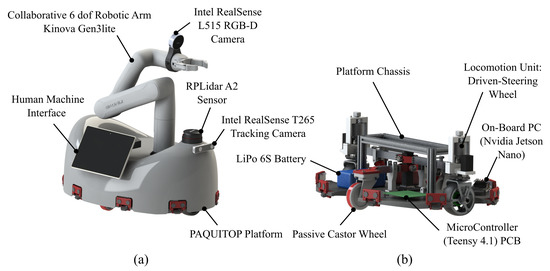
Figure 1.
Rendering of the D.O.T. PAQUITOP prototype: (a) main components; (b) base platform details.
3.1. The PAQUITOP Mobile Platform
The system was conceived of around the PAQUITOP platform, an omnidirectional platform suspended on four wheels: two standard off-center passive castor wheels and two driven wheels, which are also provided with a steering degree of freedom (locomotion units) [15]. On the one hand, such a design choice yields several advantages related to superior maneuverability and enhanced stability during highly dynamic motions [15]. On the other hand, the presence of a redundant set of actuators implies the need for a careful motion planning strategy, which must consider redundancy. A proper mechanical design of the wheel suspensions has been developed in order to guarantee steady contact with the floor and stability in all use conditions, even when the robot is passing over obstacles or is performing curved trajectories [16]. Figure 1 shows a schematic representation of the PAQUITOP prototype. Each locomotion unit is composed of a custom-designed motor wheel installed on a steering axis actuated by a stepper motor through a pinion gear transmission. Through the adoption of a hollow steering shaft and a slip ring, the motor wheel can rotate infinitely around its steering axis.
Through the adoption of two locomotion units, the platform can follow a generic 2D velocity twist reference and, therefore, is characterized by omnidirectional mobility. Because of this, high mobility is achieved through the re-orientation of the internal degrees of freedom; the term pseudo-omnidirectional is used in the following to better describe the platform’s mobility. Based on this kinematic structure, different locomotion strategies can be implemented to control the motion of the platform. Figure 2 presents the main actuation strategies that have been implemented on the base platform. Even if all these categories can be generalized in the first one (Configuration I), it is interesting to examine these cases to understand their properties and to select the best strategy according to the needed performances. Regarding the kinematics analysis of the platform, the interested reader is addressed to [15,16]. For the D.O.T. PAQUITOP project, the Configuration I has been adopted for the autonomous mode because of the necessity to exhibit high mobility in the plane of motion. Nevertheless, in the motion planning of autonomous tasks, the longitudinal motion along the x-axis of the robot is encouraged when possible, through specific weights, to exploit the dynamic advantage provided by the major axis during the acceleration and deceleration phases.

Figure 2.
Main locomotion strategies that could be implemented for the PAQUITOP pseudo-omnidirectional platform: (a) general motion is achieved through the independent control of the 2 steering angles; (b) differential drive motion; (c) pure transnational motion; (d) car-like locomotion with a front steering wheel; (e) car-like locomotion with a rear steering wheel; (f) car-like locomotion with two steering wheels.
During teleoperation tasks, the platform commands are imparted through a radio controller, the FrSky 2.4G ACCST Taranis X9D Plus. This kind of controller is usually adopted in Unmanned Aircraft Systems (UASs); thus, it provides a good selection of switches and controllers and a stable connection from a distance. In Figure 3, the layout of the radio controller is presented along with the definition of the channel nomenclature for data acquisition. All the signals from the controller are transmitted at GHz to the radio receiver, which communicates with the Controller through a serial bus.
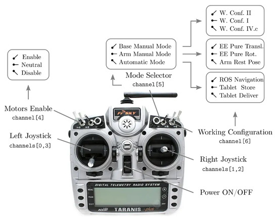
Figure 3.
Digital telemetry radio system layout.
A three-position switch is used as a mode selector: Base Manual Mode, Arm Manual Mode, Automatic Mode. When the mode selector is in Base Manual Mode, a second switch is used to select the locomotion strategy for the base platform: Configurations I, II, IV.c. When Configuration I is selected, the right joystick is used to control the linear velocity components with respect to the robot reference frame, while the angular velocity is selected with the horizontal axis of the left joystick. When Configuration II is selected, the right joystick is used to control the linear velocity along the y-axis and the angular velocity. Finally, when Configuration IV.c is selected, the right joystick is used to control the linear velocity along the x-axis and the angular velocity.
To improve the controllability of the platform in Base Manual Mode, the joystick commands are read and processed through an appropriate map function. The selected function is a piecewise-defined function composed of I-order polynomials and a V-order polynomial, as presented in Figure 4.
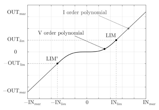
Figure 4.
Map function adopted to process the joystick commands.
The resulting function is an odd function (the concept of reverse motion has no meaning for an omnidirectional platform without a preferred moving direction), with a very low gradient around the origin, which acts as a dead-band, and it is of class . The use of a V-order function enables the choice of the coordinates of the control point LIM, while keeping a continuous transition between the two polynomials. Moreover, the function and its derivative are null at the origin. The adoption of an I-order polynomial is beneficial to the user’s drive experience, and it does not compromise the resolution at which the commands are defined. The function is fully defined once the maximum values , and the ratios , are defined. The piecewise-defined function can be written as:
where:
It is common practice to consider the limitations of the velocity of the wheels in the joystick mapping function. However, in this application, there are no velocity limitations in the desired velocity field, so no considerations have been made in this sense.
The motion control of the platform is performed on a Teensy 4.1 Controller, which receives the command velocity twist of the platform and computes the inverse kinematics to evaluate the reference values for the actuators, which are controlled through closed-loop control systems. The velocity inputs can be imparted by an operator through a remote controller or by the autonomous navigation architecture through a serial communication bus that connects the Controller to the onboard PC. Moreover, the platform is provided with eight proximity sensor systems. Each unit is composed of an ultrasonic sensor to detect obstacles around the platform and a laser-based sensor titled downwards to act as a cliff detector. All these measurements are used to ensure redundancy towards collision avoidance. On this topic, future work will focus on signal processing and collision avoidance strategies, which are under development.
3.2. Robotic Arm
To effectively interact with the surrounding environment, the system is provided with a collaborative robotic arm mounted on the PAQUITOP platform. The choice of a commercial collaborative manipulator was made by looking for a convenient compromise of the cost, performance, and weight. The selected robotic arm is the Kinova Gen3lite, a six-degree-of-freedom manipulator with an onboard controller. The mounting position and orientation of the robotic arm with respect to the base platform have been deeply investigated in previous works [18,19]. As a result of those studies, the robotic arm is mounted in an off-centered position with respect to the base footprint of the platform. On the one hand, this is fundamental to effectively performing a specific task, such as pushing a lift button or reaching out to manipulate objects on a table. On the other hand, because of the limited weight of the platform (similar to the one of the robotic arm), which makes it particularly suitable for a collaborative workspace, special attention must be paid to the stability of the whole system, which can be jeopardized under particular motion conditions. This topic is beyond the scope of this study, but it will be addressed in future investigations.
The commercial robot has been integrated into the system through its native software infrastructure provided by the manufacturer. In addition to the platform, the robotic arm can be commanded in different ways. When the mode selector of the radio controller is in Arm Manual Mode, the second switch is used to select different working configurations: EE Pure Translation, EE Pure Rotation, Arm Rest pose. When EE Pure Translation is selected, the right joystick is used to move the End-Effector (EE) on a plane at a constant height from the ground, while the left joystick is used to move the EE in the vertical direction. When EE Pure Rotation is selected, the controllers are used to tilt the EE, while keeping the end-effector frame origin fixed in space. In these cases, the angles of the joystick are converted into 3D velocity twists through the aforementioned mapping function (1). Then, the numerical inverse kinematics of the robotic arm is computed, and the joint velocities commands are sent to the built-in actuators’ controller. To simplify the arm retracting action, an automatic procedure is activated when Arm Rest pose is selected. This procedure retracts the robotic arm to the rest position, presented in Figure 1a. This configuration is beneficial during navigation because it lowers the center of mass of the system, thus improving the dynamic stability of the robot. Two automatic procedures have been implemented to extend the HMI or specific sensors toward the user and to retract them when requested. These actions can be commanded by the switches on the radio controller or through buttons on the HMI, but the same logic could be applied to an unconventional HMI such as gesture-based, eye-gaze-based, or voice-based ones.
To fully perceive and obtain information from the surroundings, exteroceptive sensors must be adopted. To provide this information, an RGB-D camera, the Intel RealSense L515, is mounted on the sixth link of the manipulator. The data are processed to generate depth cloud points as outputs that represent the entire field of view area. With the use of image recognition techniques, the camera both recognizes the object and calculates an associated reference frame. Once the posture of the robot is known, this information can be converted into the position and orientation of the object with respect to the base frame of the robot, allowing it to reach the object and interact with it. As mentioned before, this sensor has been included for the future development of more advanced autonomous pick and place capabilities.
3.3. Application-Oriented Sensors
The aforementioned system may be seen as a general-purpose mobile manipulator for indoor applications. To effectively provide assistance in hospital environments, the D.O.T. PAQUITOP robot must be customized with task-oriented sensors. As presented in Section 2, the prototype may be adopted to measure and store the vital parameters of patients before, during, and after blood collection or transfusion or during the day in an inpatient facility of the hospital. For this task, many devices could be adopted. To speed up the prototyping phase, the selection of measuring systems has been oriented towards open-source solutions, such as HealthyPi, an open vital sign monitoring development kit, or academic projects such as [24,25]. These kinds of kits are usually composed of a pulse oximeter, sensors for Electrocardiogram (ECG) data, heart rate and heart rate variability, respiration frequency, and body temperature measurements. At this stage of the D.O.T. PAQUITOP project, the focus is on the validation of the effectiveness of this robotic assistant in the hospital environment. Future investigations will focus on clinical trials to test the accuracy of different measuring systems. Another important feature to be implemented is the ability to perform the matching check between the blood bag and the patient. Since both the blood bag and the patient at Molinette Hospital are provided with an NFC tag, this matching check can be easily automated, through proper NFC readers connected to the onboard PC. The sensors for vital measuring parameters and the NFC readers are installed on the HMI holder and deployed by the robotic arm when necessary.
3.4. Control Architecture
In order to be properly controlled, both in manual and autonomous mode, the following control architecture has been conceived of and implemented. The control architecture could be seen as composed of two modules: low-level and high-level. The low-level control system collects all hardware and software components that are required to effectively control the base functionalities of the robot. The term is used in contrast with the high-level control architecture, which provides the platform features such as autonomous navigation, feature recognition, task execution, robotic arm control, and communications through a custom Human–Machine Interface (HMI).
The low-level control module was conceived of around a USB-based Controller development unit, the Teensy 4.1 by PJRC, which is programmed to read the inputs from the radio controller (remote control mode) or the onboard PC (autonomous mode), to compute the inverse kinematics according to the working configuration selected, to close the loop control on the actuated degrees of freedom, and to check the presence of obstacles through the feedback given by the proximity sensors module. A schematic representation of this control architecture is presented in Figure 5.
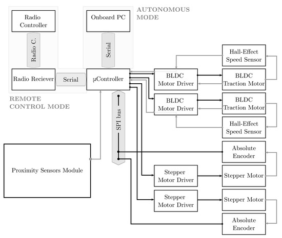
Figure 5.
Schematic representation of the Low-Level Control Architecture (L-LCA).
Regarding high-level control, a framework based on the Robot Operating System (ROS), the de facto standard in service robotics applications, was adopted for all tasks implemented on the onboard PC, an NVIDIA Jetson Nano. In particular, an activity manager is responsible for receiving the inputs from the HMI, and based on the current state of the robot, it activates certain operations. A schematic representation of the high-level control architecture is presented in Figure 6.
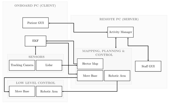
Figure 6.
Schematic representation of the High-Level Control Architecture (H-LCA).
A detailed description of the control architecture is beyond the scope of this article, but further documentation will be uploaded to the shared GitHub folder.
4. Experimental Tests
To experimentally prove the effectiveness of the proposed mobile manipulator, first, a preliminary demonstration was conducted in the Politecnico di Torino laboratories. This environment presents some similarities to the hospital one, where the final demonstration took place at the end of July 2022. In fact, both spaces are characterized by rectangular rooms connected by straight corridors. To simulate the transfusion seats, two stations were prepared. Each station was composed of a seat, with a height similar to the hospital seat, and a vertical rod, which simulates the IV pole that holds the blood bag. Since the capabilities needed for Application 2 (Section 2) are included in those required for Application 1, this preliminary demo simulates only the first scenario. In order to avoid issues related to the patients’ sensitive data, the hospital dataset related to the NFC tag was not used. On the contrary, a facsimile dataset was created and connected to ArUco Markers [26]. In this dataset, each patient is associated with a unique code. A second dataset collects all the identifiers of the blood bags, and a third one collects the pairs of identifiers that represent the patient and the associated blood bag. The ArUco Markers are placed in the same position as the NFC tags: one on the blood bag and the other on the patient’s wrist. Thus, with the correct NFC reader and the required permissions, the system could be integrated into the hospital’s IT network. In the following, a brief description of the experimental test is detailed.
In the setup phase, the D.O.T. PAQUITOP mobile manipulator was manually driven through the different rooms, and the positions of the stations were saved with respect to the starting point, where a docking station for recharging could eventually be placed. During the experimental test, the mobile manipulator was asked to autonomously navigate from a starting point to the first station. Once it arrives, the blood bag identifier is read and saved. Then, PAQUITOP autonomously takes the HMI from its support on the base platform and lifts it toward the patient to start the interaction. Figure 7 presents the human–machine interface developed for this validation test. After a brief presentation, the robot asks the patient to show his/her identifier to perform the matching check. When the identifier is detected and read, the gray button on the HMI turns green and the text on the button updates to provide positive feedback to the user (e.g., “Hi Name of the Patient!”). Later, the robot asks the patient if he/she needs help. If so, the request is saved and reported to the medical staff. For now, the body temperature of the patient is measured through a thermal camera connected to the onboard PC and installed close to the RGB-D camera. In the future, different measuring systems, such as those presented in Section 3.3, will be tested. The data are acquired after the patient presses the blue button on the HMI. In the future, an autonomous procedure, based on image recognition techniques, could be implemented to perform this task. When the acquisition is complete, the robot navigates to the next station and performs the same operations. When all stations are covered, the robot returns to the starting point and generates a report for the medical staff.
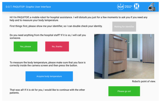
Figure 7.
HMI developed for the experimental test.
This experimental test was performed multiple times to qualitatively validate the robustness of the D.O.T. PAQUITOP concept and implementation. Figure 8 presents the mapped environment with the simulated stations and the performed tasks. From the starting point (h), the robot autonomously navigates to the first station (s1), where it performs the matching check and interacts with the patient through the HMI. Then, it repeats these operation at station s2, and it returns to the home position (h). At each station, the blood bag identifier is read (sX.1), the HMI is deployed towards the user (sX.2), the matching check between the blood bag and the patient is performed (sX.3), and finally, the patient can interact through the HMI presented before. In this experimental phase, the mobile manipulator was proven to be successful in all the tries.
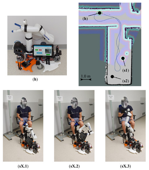
Figure 8.
Synthetic representation of the experimental demo: (h) home position representing the future charging station; (s1), (s2) two stations for transfusion; (sX.1) the robot detects the blood bag identifier; (sX.2) the robot deploys the HMI towards the user; (sX.3) the robot performs the matching check and interacts with the patient through the HMI.
At the end of July, 2022, in the hematology ward at Molinette Hospital, a qualitative validation test was performed to prove the effectiveness of the robot in the real application environment. At the hospital, the same sequence was performed with one of the project team members acting as a patient on a transfusion seat (Figure 9). The previously described procedure was tested five times with two stations. During the tests, the robot reached the desired position in front of the transfusion seat and correctly deployed and oriented the HMI toward the patient. Therefore, the tests can be considered successful. Moreover, the limited footprint of the robot and its omnidirectional mobility played key roles in the navigation in such a cluttered environment. Nevertheless, some drawbacks are highlighted. In particular, because of the geometry of the obstacles inside the hospital ward, a 2D Lidar for obstacle avoidance may not be enough in every situation. For this reason, future improvements will focus on the 3D representation of the environment.
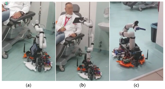
Figure 9.
D.O.T. PAQUITOP mobile manipulator during the validation test at the hematology ward, Molinette Hospital: (a) D.O.T. PAQUITOP approaching the transfusion seat; (b) D.O.T. PAQUITOP interacting with the patient; (c) D.O.T. PAQUITOP navigating through the hospital ward.
5. Conclusions
The use of robotic technologies for caregiving and assistance has become a very interesting research topic in the field of robotics. In particular, service robotics is gaining the ever-growing interest of markets, industries, and researchers. The use of these technologies in the caregiving sector could relieve the pressure on hospital operators, providing basic assistance that does not require advanced skills and expertise. In this scenario, this paper presented D.O.T. PAQUITOP, a mobile manipulator for autonomous applications in the field of hospital assistance. This project has been created in collaboration with the non-profit organization Fondazione D.O.T. and the medical staff of Molinette Hospital in Turin (Italy). Through this collaboration, two main applications have been identified for the D.O.T. PAQUITOP prototype. In the first one, the robot is adopted to help the operators of the blood bank of the hospital during transfusions, while in the second one, the robot is used to transport tools and samples from one place of the ward to another, relieving the pressure of the job on the human staff. The mobile robot is composed of an omnidirectional platform, named PAQUITOP, a commercial 6-dof robotic arm, sensors for vital sign monitoring, and a tablet to interact with the user.
The robot has been fully prototyped and qualitatively tested in the laboratories of the Politecnico di Torino and at the hematology ward at Molinette Hospital. During these tests, the robot proved to be successful in the execution of the requested tasks, while some limitations were highlighted. Now that the effectiveness of the solution has been tested, future developments will focus on the 3D representation of the environment to improve the obstacle avoidance during the robotic arm motions, on a deeper analysis of the human–machine interaction, and on the customization of the robot’s sensors to address different assistive tasks.
Author Contributions
Conceptualization, L.T., G.Q., L.B. and C.V.; methodology, L.T., G.Q. and L.B.; software, L.B. and L.T.; validation, L.T., L.B., G.C. and A.B.; formal analysis, L.T. and L.B.; investigation, L.T., L.B. and G.C.; writing—original draft preparation, L.T.; writing—review and editing, L.T., L.B., G.C., A.B., C.V. and G.Q.; visualization, L.T. and L.B.; supervision, A.B., C.V. and G.Q.; project administration, C.V. and G.Q. All authors have read and agreed to the published version of the manuscript.
Funding
This research received no external funding.
Institutional Review Board Statement
Not applicable.
Informed Consent Statement
Not applicable.
Data Availability Statement
The data presented in this study are available upon request from the corresponding author.
Acknowledgments
This work was developed with the contribution of the non-profit organization Fondazione D.O.T. (https://www.fondazionedot.it/wp/, accessed on 11 December 2022) and the Politecnico di Torino Interdepartmental Centre for Service Robotics PIC4SeR (https://pic4ser.polito.it, accessed on 11 December 2022)).
Conflicts of Interest
The authors declare no conflict of interest.
References
- Romero-Garcés, A.; Martínez-Cruz, J.; Inglés-Romero, J.F.; Vicente-Chicote, C.; Marfil, R.; Bandera, A. Measuring quality of service in a robotized comprehensive geriatric assessment scenario. Appl. Sci. 2020, 10, 6618. [Google Scholar] [CrossRef]
- Lutz, W.; Sanderson, W.; Scherbov, S. The coming acceleration of global population aging. Nature 2008, 451, 716–719. [Google Scholar] [CrossRef] [PubMed]
- Sander, M.; Oxlund, B.; Jespersen, A.; Krasnik, A.; Mortensen, E.L.; Westendorp, R.G.J.; Rasmussen, L.J. The challenges of human population aging. Age Ageing 2015, 44, 185–187. [Google Scholar] [CrossRef] [PubMed]
- Yang, G.Z.; Nelson, B.J.; Murphy, R.R.; Choset, H.; Christensen, H.; H. Collins, S.; Dario, P.; Goldberg, K.; Ikuta, K.; Jacobstein, N.; et al. Combating COVID-19—The role of robotics in managing public health and infectious diseases. Sci. Robot. 2020, 5, eabb5589. [Google Scholar] [CrossRef] [PubMed]
- Vercelli, A.; Rainero, I.; Ciferri, L.; Boido, M.; Pirri, F. Robots in elderly care. Digit.-Sci. J. Digit. Cult. 2018, 2, 37–50. [Google Scholar]
- Kabacińska, K.; Prescott, T.J.; Robillard, J.M. Socially assistive robots as mental health interventions for children: A scoping review. Int. J. Soc. Robot. 2021, 13, 919–935. [Google Scholar] [CrossRef]
- Abdi, J.; Al-Hindawi, A.; Ng, T.; Vizcaychipi, M.P. Scoping review on the use of socially assistive robot technology in elderly care. BMJ Open 2018, 8, e018815. [Google Scholar] [CrossRef] [PubMed]
- Gouaillier, D.; Hugel, V.; Blazevic, P.; Kilner, C.; Monceaux, J.; Lafourcade, P.; Marnier, B.; Serre, J.; Maisonnier, B. Mechatronic design of NAO humanoid. In Proceedings of the 2009 IEEE International Conference on Robotics and Automation, Kobe, Japan, 12–17 May 2009; pp. 769–774. [Google Scholar]
- Fujita, M. AIBO: Toward the era of digital creatures. Int. J. Robot. Res. 2001, 20, 781–794. [Google Scholar] [CrossRef]
- Góngora Alonso, S.; Hamrioui, S.; de la Torre Díez, I.; Motta Cruz, E.; López-Coronado, M.; Franco, M. Social robots for people with aging and dementia: A systematic review of literature. Telemed. e-Health 2019, 25, 533–540. [Google Scholar] [CrossRef] [PubMed]
- Gasteiger, N.; Loveys, K.; Law, M.; Broadbent, E. Friends from the future: A scoping review of research into robots and computer agents to combat loneliness in older people. Clin. Interv. Aging 2021, 16, 941. [Google Scholar] [CrossRef] [PubMed]
- Yatsuda, A.; Haramaki, T.; Nishino, H. A study on robot motions inducing awareness for elderly care. In Proceedings of the 2018 IEEE International Conference on Consumer Electronics-Taiwan (ICCE-TW), Taichung, Taiwan, 19–21 May 2018; pp. 1–2. [Google Scholar]
- Mundher, Z.A.; Zhong, J. A real-time fall detection system in elderly care using mobile robot and kinect sensor. Int. J. Mater. Mech. Manuf. 2014, 2, 133–138. [Google Scholar] [CrossRef]
- Mahmud, S.; Lin, X.; Kim, J.H. Interface for human machine interaction for assistant devices: A review. In Proceedings of the 2020 10th Annual Computing and Communication Workshop and Conference (CCWC), Las Vegas, NV, USA, 6–8 January 2020; pp. 768–773. [Google Scholar]
- Carbonari, L.; Botta, A.; Cavallone, P.; Quaglia, G. Functional design of a novel over-actuated mobile robotic platform for assistive tasks. In Proceedings of the International Conference on Robotics in Alpe-Adria Danube Region, Kaiserslautern, Germany, 19 June 2020; pp. 380–389. [Google Scholar]
- Tagliavini, L.; Botta, A.; Cavallone, P.; Carbonari, L.; Quaglia, G. On the suspension design of paquitop, a novel service robot for home assistance applications. Machines 2021, 9, 52. [Google Scholar] [CrossRef]
- Tagliavini, L.; Botta, A.; Carbonari, L.; Quaglia, G.; Gandini, D.; Chiaberge, M. Mechatronic design of a mobile robot for personal assistance. In Proceedings of the International Design Engineering Technical Conferences and Computers and Information in Engineering Conference, American Society of Mechanical Engineers, Online, 17–19 August 2021; Volume 85437, p. V007T07A044. [Google Scholar]
- Carbonari, L.; Tagliavini, L.; Botta, A.; Cavallone, P.; Quaglia, G. Preliminary observations for functional design of a mobile robotic manipulator. In Proceedings of the International Conference on Robotics in Alpe-Adria Danube Region, Poitiers, France, 21–23 June 2021; pp. 39–46. [Google Scholar]
- Colucci, G.; Tagliavini, L.; Carbonari, L.; Cavallone, P.; Botta, A.; Quaglia, G. Paquitop. arm, a Mobile Manipulator for Assessing Emerging Challenges in the COVID-19 Pandemic Scenario. Robotics 2021, 10, 102. [Google Scholar] [CrossRef]
- Tagliavini, L.; Baglieri, L.; Botta, A.; Colucci, G.; Cavallone, P.; Visconte, C.; Quaglia, G. Dot paquitop: A mobile robotic assistant for the hospital environment. In Proceedings of the Jc-IFToMM International Symposium, Kyoto, Japan, 16 July 2022; pp. 88–94. [Google Scholar]
- Saat, S.; Abd Rashid, W.; Tumari, M.; Saealal, M. Hectorslam 2d Mapping For Simultaneous Localization and Mapping (Slam). In Proceedings of the Journal of Physics: Conference Series, Bandung, Indonesia, 25–27 November 2019; Volume 1529, p. 042032. [Google Scholar]
- Alag, G. Evaluating the Performance of Intel Realsense T265 Xsens Technologies BV. Master’s Thesis, University of Twente, Enschede, The Netherlands, 2020. [Google Scholar]
- Lourenço, F.; Araujo, H. Intel RealSense SR305, D415 and L515: Experimental Evaluation and Comparison of Depth Estimation. In Proceedings of the VISIGRAPP (4: VISAPP), Online, 8–10 February 2021; pp. 362–369. [Google Scholar]
- Naik, S.; Sudarshan, E. Smart healthcare monitoring system using raspberry Pi on IoT platform. ARPN J. Eng. Appl. Sci. 2019, 14, 872–876. [Google Scholar]
- Kaur, A.; Jasuja, A. Health monitoring based on IoT using Raspberry PI. In Proceedings of the 2017 International conference on computing, communication and automation (ICCCA), Greater Noida, India, 5–6 May 2017; pp. 1335–1340. [Google Scholar]
- Garrido-Jurado, S.; Muñoz-Salinas, R.; Madrid-Cuevas, F.J.; Medina-Carnicer, R. Generation of fiducial marker dictionaries using mixed integer linear programming. Pattern Recognit. 2016, 51, 481–491. [Google Scholar] [CrossRef]
Disclaimer/Publisher’s Note: The statements, opinions and data contained in all publications are solely those of the individual author(s) and contributor(s) and not of MDPI and/or the editor(s). MDPI and/or the editor(s) disclaim responsibility for any injury to people or property resulting from any ideas, methods, instructions or products referred to in the content. |
© 2023 by the authors. Licensee MDPI, Basel, Switzerland. This article is an open access article distributed under the terms and conditions of the Creative Commons Attribution (CC BY) license (https://creativecommons.org/licenses/by/4.0/).