Abstract
The seismoelectric effect of porous media is the main basis for seismoelectric logging. At present, most of the studies on the seismoelectric effect in unsaturated porous media adopt the model of pores with continuous distribution of gas and liquid. There is a lack of theoretical research on the micro mechanism of the seismoelectric effect of unsaturated porous media with discrete gas phase, and the existing studies do not consider the effect of the electric double layer at the gas–liquid interface on the seismoelectric effect. Based on the capillary model, this work adopted the gas phase discrete model, combined the electric double layer theory and the seepage principle, considered the effect of electric double layer at the pore wall and the gas–liquid interface, and studied the micro principle of the seismoelectric effect of unsaturated porous media. Firstly, we studied the variation of gas–water two-phase flow pattern with saturation in unsaturated pores, then proposed the equivalent principle of series circuits, deduced the effective streaming current and conductance of a pore containing multiple bubbles, and then deduced the streaming potential coupling coefficient in the unsaturated pores. We also studied the effect of pore parameters such as saturation, pore size, bubble spacing, pore fluid viscosity, and salinity on the streaming potential coupling coefficient. The results show that the streaming potential coupling coefficient first increases and then decreases with the decrease in saturation, which is the same as the trend measured in Allègre’s experiment, and provide a theoretical explanation for the non-monotonic change in the coupling coefficient with saturation in unsaturated porous media.
1. Introduction
The seismoelectric effect is the conversion from acoustic energy to electrical energy in porous media, and is mainly caused by the electric double layer in the pore. For unsaturated porous media, there is an electric double layer at the gas–liquid interface, which cannot be ignored when studying the seismoelectric effect of unsaturated porous media.
The studies on the mechanism of the seismoelectric effect in saturated porous media are quite mature, and these studies provide a theoretical basis for the study of the seismoelectric effect in unsaturated pores. In 1953, Packard proposed a micro model of electromagnetic field induced by acoustic field in the capillary pore, and calculated the streaming potential coupling coefficient [1]. In 1989, Pride also investigated the seismoelectric conversion in the capillary, deducing the coupling coefficient [2]. In 1991, Pride deduced the electrokinetic coupling coefficient in slit-like pores, and studied the energy dissipation problems caused by the seismoelectric effect [3]. In 1994, Pride deduced the macroscopic coupling governing equations of the acoustic field and the electromagnetic field in a porous medium, which provide a theoretical basis for the study of the seismoelectric effect [4]. From 2010 to 2012, Glover et al. modified the classical HS equation by using the empirical formulas of zeta potential, conductivity, viscosity, and other parameters, and proposed a new expression of the streaming potential coupling coefficient [5,6].
A lot of studies have also been carried out on the seismoelectric effect of unsaturated porous media. In 1994, Wurmstich studied the coupling coefficient of streaming potential in unsaturated porous media [7]. He suggested that bubbles would reduce the conductivity of pore fluid and would produce an amplification factor for the coupling coefficient. His theory did not consider the influence of bubbles on streaming current and lacked strict theoretical derivation. Revil and Darnet modified the conductivity of the HS equation of saturated porous media according to Archie’s theorem, and they suggested that the coupling coefficient is inversely proportional to the water saturation [8,9]. In 1999, Pirrier gave the empirical formula of streaming potential coupling coefficient of unsaturated porous media, considering the influence of water phase permeability [10]. He suggested that the coupling coefficient is positively related to saturation. In 2007, Revil and Linde deduced the electrokinetic coupling coefficient of unsaturated porous media [11,12], and the streaming current was obtained by multiplying the volume average of net residual charge density and the seepage velocity of aqueous phase, which is inconsistent with that obtained through Slattery volume average [13]. From 2010 to 2015, Allègre conducted periodic drainage experiments and proposed an empirical formula for the streaming potential coupling coefficient according to the experimental measurement data [14,15,16]. Allègre suggested that the streaming potential coupling coefficient first increases and then decreases with the decrease in water saturation, but he did not give a specific mathematical model for his theory.
The current studies about the seismoelectric effect of unsaturated porous media mainly adopt the model that the gas and liquid phases are respectively continuous [8,9,10,11,12,13]. According to the experiment of Serizaw in 2002 [17], the gas and water phases in the unsaturated porous media have various flow patterns: not only the gas phase continuous annular flow and liquid mass flow, but also the gas phase discrete bubbly flow and slug flow, so the model that the gas and liquid are respectively continuous is not suitable for all cases of acoustoelectric conversion in unsaturated porous media, and there is a lack of research on the seismoelectric effect in gas phase discrete unsaturated porous media. From 2007 to 2013, Sherwood studied the seismoelectric effects in a single capillary whose gas phase is discrete and calculated the streaming potential coupling coefficient [18,19,20]. However, Sherwood only studied the pore containing a single bubble, and the bubble and liquid do not move synchronously in his model, which is inconsistent with the actual model. According to Creux’s research, although there is an electric double layer at the gas–liquid interface [21], the existing theory does not consider the influence of the double electric layer at the gas–liquid interface on the seismoelectric effect [7,8,9,10,11,12,13].
Based on the above background, this work firstly studied the micro mechanism of acoustoelectric conversion in gas phase discrete unsaturated pores under the excitation of a steady acoustic field. Using the capillary model [22], we studied the change in gas–liquid two-phase flow pattern in the pore with saturation. Considering the influence of the electric double layer at the gas–liquid interface, using the boundary conditions satisfied by the gas–liquid surface in Refs. [23,24], we proposed the principle of series circuit equivalence to calculate the effective streaming current and conductance of the bubbly flow and the slug flow, and further deduced the streaming potential coupling coefficient in the pore under the excitation of a steady acoustic field. We mainly studied the influence of saturation on the seismoelectric effect, and the effect of other parameters such as pore size, bubble spacing, viscosity, and salinity on the coupling coefficient of the capillary was also investigated. This work provides a theoretical explanation on the micro level for the non-monotonic change in streaming potential coupling coefficient with saturation, and also provides theoretical guidance for the further study of the macro seismoelectric effect of gas phase discrete unsaturated porous media, which can further explain some physical phenomena in the process of seismoelectric logging.
2. Materials and Methods
The gas–water two-phase flow pattern in the pores of unsaturated porous media is related to various formation parameters, such as saturation, pore structure, pore size, water phase flow velocity, and pore wettability. In 2002, Serizaw [17] used a high-speed camera system to observe the flow pattern in a micro cylindrical silicon tube. The flow pattern is mainly divided into gas phase discrete bubbly flow, slug flow, gas phase continuous annular flow, and liquid mass flow, which is very similar to the gas–water two-phase flow pattern in the pore.
In Serizaw’s experiments, when the content of the gas phase is low in the micro tube, the stiffness of the bubbles is high, and the bubbles always remain spherical, making the coalescence lose its foundation, and there is bubbly flow in the pore at this time. To simplify the model, we make the following assumptions:
- spherical bubbles are located on the pore axis;
- the bubbles are the same size;
- bubble spacing is the same.
The simplified bubbly flow model in the pore is shown in Figure 1.
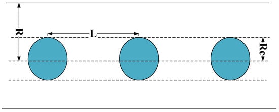
Figure 1.
Bubbly flow in the pore.
When the content of the gas phase in the pore is high, and the velocity of the long bubbles is not enough to overcome the strong surface tension of the liquid bridge between them, a slug flow occurs. The bubbles are cylindrical with two hemispherical tail caps, and the size is larger than the pore radius, known as the Bretherton bubble [25]. At this time, the bubbles are located on the pore axis, and the size and spacing of the bubbles are the same. The slug flow model in the pore is shown in Figure 2.

Figure 2.
Slug flow in the pore.
The unsaturated pore model studied in this paper is as follows:
- the liquid phase is continuous and the gas phase is discrete;
- the bubbles are non-sticky, and their presence does not affect the flow of the liquid;
- the bubbles are not deformed, move synchronously with the liquid, and the distance between the bubbles is the same;
- when the saturation is high, the gas phase is dominated by spherical bubbles and, as the saturation decreases, the bubbles gradually become larger and become Bretherton bubbles.
2.1. Equivalent Principle of Series Circuit
The starting position between two bubbles in the pore can be regarded as a unit, and the effective streaming current and conductivity of each unit can be regarded as the effective streaming current and conductivity of two-phase flow pores. Each unit can be divided into two parts, one part contains bubbles and the other part does not contain bubbles. The calculation of the effective streaming current and conductance in each unit can be carried out by analogy with the principle of series circuits. The study in this paper is based on steady conditions, so the generated electric field in the pore is a steady electric field.
Some parameters used in this paper are shown in Table 1 below.

Table 1.
Model parameters.
The subscript indicates the parameters of the gas bearing part. The subscript represents the parameter of the gas free part. The subscript indicates the effective parameter in the pore.
The current of the part containing bubbles can be expressed as:
The current in the part without bubbles is:
The effective current of the whole unit is:
In a series circuit, the current is equal everywhere, so:
The total acoustic pressure drop of the unit is equal to the sum of the acoustic pressure drop of each part:
The total voltage drop of the unit is equal to the sum of the voltage drops of each part:
is the unit length, is the length of the part with bubbles, is the length of the part without bubbles.
So, we can deduce that:
We can further obtain the effective conductance of the unit:
Similarly, the effective streaming current coupling coefficient of the element is deduced:
2.2. Seismoelectric Effect of Bubbly Flow
When the saturation in the pore is high, there is bubbly flow in the pore. Using the boundary conditions of the acoustic field in the literature [23,24]: the liquid and the gas velocity at the interface are the same, the gas has no viscosity and does not affect the velocity of the liquid, and the water phase velocity is:
The distribution of ions in the electric double layer on the surface of the pore wall [4,26] can be obtained:
, , , and .
There is an electric double layer at the gas–liquid interface [21], and the shear potential ranges from −20 mv to −40 mv. Distribution of ions in the electric double layer on the surface of spherical bubbles is:
, , and .
The streaming current generated by the electric double layer near the pore wall [18] is:
where .
There is no motion of the fluid near the spherical bubble surface relative to the gas–liquid interface, so the electric double layer at the bubble surface does not contribute to the streaming current.
We can obtain the conductance of the region with the bubbles:
is the conductance near the pore wall, which is calculated according to Ref. [3]:
is the conductance near the surface of the spherical bubble:
, is the volume of liquid in the region where the bubble is located, is the bubble radius.
The conductance of the bubble-free region of the unit is:
is the volume of liquid in the region without bubbles.
The relationship between spherical bubble radius and water saturation is:
We can deduce the effective conductance of the bubbly flow unit:
When the acoustic pressure gradient of each section in the bubbly flow unit is 1, the streaming current coupling coefficient is equal to the streaming current:
Then, we can deduce the effective streaming potential coupling coefficient of the bubbly flow:
2.3. Seismoelectric Effect of Slug Flow
With the decrease in water saturation in the pore, the bubble gradually becomes larger and, to a certain extent, the bubble becomes a Bretherton bubble [25], and there is slug flow in the pore.
The relative velocity of the fluid near the gas–liquid interface of the cylindrical bubble is:
The distribution of ions near the gas–liquid interface of the cylindrical bubble is:
, , and .
The streaming current of the part where the cylindrical bubble is located is:
is the streaming current generated by the electric double layer near the surface of the cylindrical bubble:
where .
The conductance of the part containing the cylindrical bubble is:
is the conductance generated by the pore wall electric double layer:
is the conductance near the surface of the cylindrical bubble:
, is the volume of liquid in the area where the cylindrical bubble is located.
The relationship between the length of the cylindrical bubble part and the water saturation is:
The slug flow unit can be regarded as a bubbly flow unit connected with a cylindrical bubble part. According to the equivalent principle of series current, we can deduce the effective streaming current coupling coefficient of the slug flow unit:
The effective conductance of a bubbly flow unit is:
, and .
We can deduce the effective conductance in the slug flow:
When the acoustic pressure gradient of each section in the slug flow unit is 1, the streaming current is equal to the streaming current coupling coefficient. So, we can deduce the effective streaming potential coupling coefficient of the slug flow:
3. Simulation and Discussion
We first study the streaming potential coupling coefficient in pores under the condition of bubbly flow when the saturation is high, investigate the influence of pore size, bubble spacing, viscosity, and salinity, and focus on the variation of the coupling coefficient with saturation.
Figure 3 studies the influence of saturation on the streaming potential coupling coefficient of the capillary under the condition of bubbly flow. It can be seen from the figure that the coupling coefficient gradually increases with the decrease in water saturation. The gas is non-conductive, and with the decrease in saturation, the bubble volume increases, the effective conductance of pore fluid decreases, the coupling coefficient is inversely proportional to the conductance, and the streaming current in the pore is almost unchanged, so the coupling coefficient will increase.
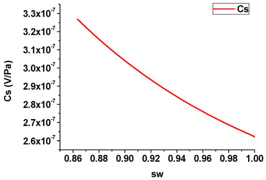
Figure 3.
Variation of streaming potential coupling coefficient with saturation (bubbly flow).
Figure 4 investigates the effect of the pore size on the streaming potential coupling coefficient of the capillary under the condition of bubbly flow. The pore radius is taken as 0.2 , 0.4 , 0.6 , 0.8 , and 1 , respectively. It can be seen from the figure that the coupling coefficient gradually increases with the increase in pore radius. As the pore size increases, the streaming current will increase and the change of pore fluid conductivity is very small, so the coupling coefficient will become larger.
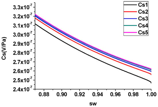
Figure 4.
Influence of pore size on streaming potential coupling coefficient (bubbly flow).
Figure 5 studies the effect of pore fluid salinity on the streaming potential coupling coefficient of the capillary under the condition of bubbly flow. The salinity is taken as 0.015 mol/L, 0.03 mol/L, 0.045 mol/L, 0.06 mol/L, and 0.075 mol/L, respectively. It can be seen from the figure that with the increase in salinity, the coupling coefficient gradually decreases. As the salinity of the pore fluid increases, the shear potential of the electric double layer will decrease, and the streaming current will decrease, so the coupling coefficient will decrease.
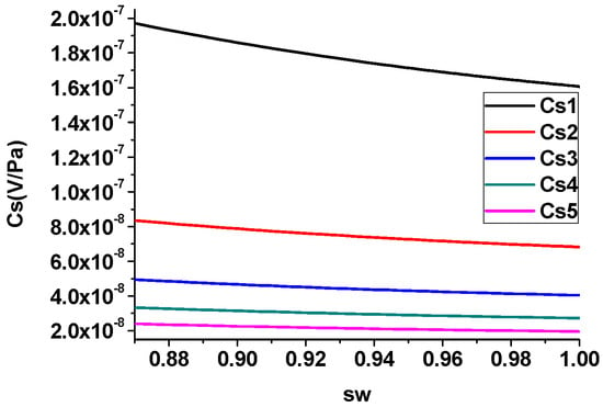
Figure 5.
Influence of salinity on streaming potential coupling coefficient (bubbly flow).
Figure 6 investigates the effect of pore fluid viscosity on the streaming potential coupling coefficient of the capillary in the bubbly flow case. The viscosity is taken as 0.001 , 0.002, 0.003 , 0.004 , and 0.005 , respectively. It can be seen from the figure that as the viscosity increases, the coupling coefficient gradually decreases. With the increase in viscosity, the seepage velocity of pore fluid will decrease, and the gradient of pore fluid seepage velocity will decrease, so the streaming current will decrease, resulting in the decrease in coupling coefficient.
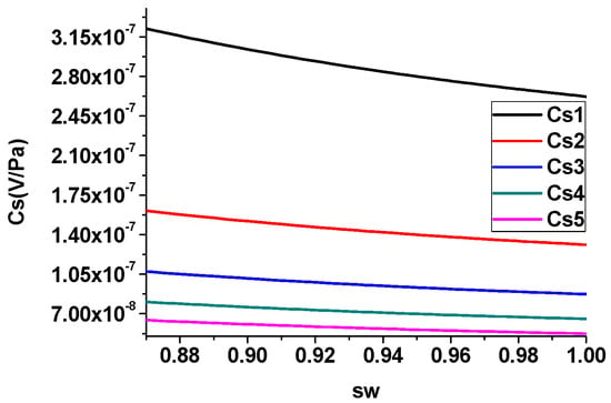
Figure 6.
Influence of viscosity on streaming potential coupling coefficient (bubbly flow).
Figure 7 studies the effect of the bubble spacing on the streaming potential coupling coefficient of the capillary in the condition of bubbly flow. The bubble spacing is taken as , , , , and , respectively, and . It can be seen from the figure that with the increase in the bubble distance, the coupling coefficient gradually increases. Under the same saturation, when the bubble spacing becomes larger, the effective conductance of the pore fluid becomes smaller, and the coupling coefficient becomes larger.
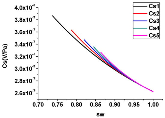
Figure 7.
Influence of bubble spacing on streaming potential coupling coefficient (bubbly flow).
We also studied the streaming potential coupling coefficient in the pore under the condition of slug flow when the saturation is low, investigated the effect of pore size, water film thickness, pore fluid viscosity, and salinity, and mainly investigated the change in coupling coefficient with saturation.
Figure 8 studies the influence of saturation on the streaming potential coupling coefficient of the capillary in the slug flow case. It can be seen from the figure that the coupling coefficient gradually decreases with the decrease in saturation. As the saturation decreases, the effective conductance of the pore liquid decreases, but the direction of the relative velocity of the fluid near the gas–liquid surface of the cylindrical bubble is opposite to the direction of the seepage velocity of the pore liquid, and the streaming current generated near the gas–liquid surface is opposite that near the pore wall. With the decrease in water saturation, the effective streaming current in pore fluid decreases, so the coupling coefficient decreases.
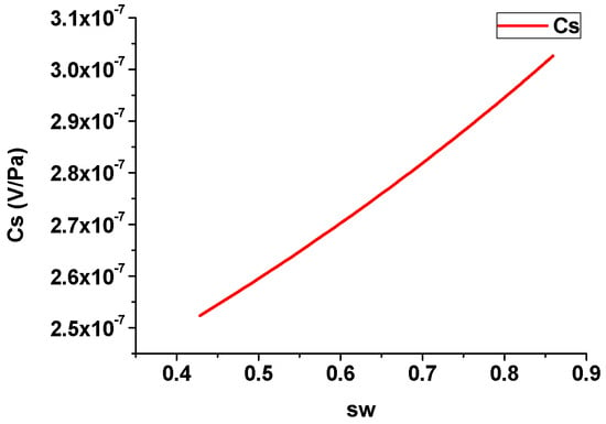
Figure 8.
Variation of streaming potential coupling coefficient with saturation (slug flow).
Figure 9 investigates the effect of water film thickness on the streaming potential coupling coefficient of the capillary under the condition of slug flow. The water film thickness is taken as , , , , and , respectively, is the radius of the pore. It can be seen from the figure that with the increase in the water film thickness, the coupling coefficient gradually decreases. When the thickness of the water film increases, under the same water saturation, the length of the cylindrical part of the bubble will increase, resulting in the decrease in the effective streaming current in the pore, so the coupling coefficient will decrease.
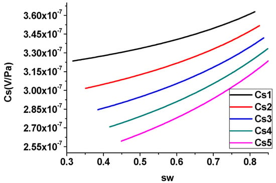
Figure 9.
Influence of water film thickness on streaming potential coupling coefficient (slug flow).
Figure 10 studies the influence of pore size on the streaming potential coupling coefficient of the capillary under slug flow. The pore radius is taken as 0.2, 0.4, 0.6, 0.8 , and 1, respectively. It can be seen from the figure that the coupling coefficient gradually increases with the increase in pore radius. As the pore radius increases, the streaming current will increase, and the change in pore fluid conductivity is small, so the coupling coefficient will become larger.
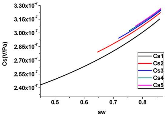
Figure 10.
Influence of pore size on streaming potential coupling coefficient (slug flow).
Figure 11 investigates the effect of fluid salinity on the streaming potential coupling coefficient of the capillary in the slug flow case. The salinity is taken as 0.015 mol/L, 0.03 mol/L, 0.045 mol/L, 0.06 mol/L, and 0.075 mol/L, respectively. It can be seen from the figure that the coupling coefficient gradually decreases with the increase in salinity. With the increase in pore fluid salinity, the shear potential of the electric double layer and the streaming current will decrease, so the coupling coefficient will decrease.
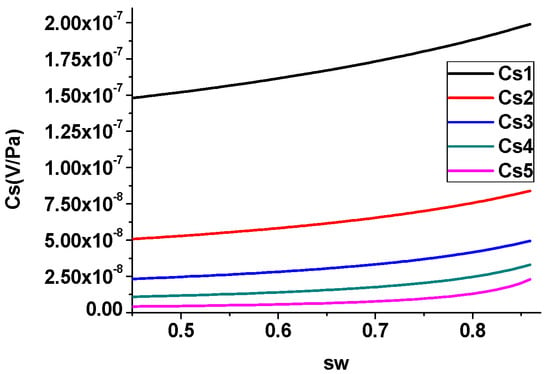
Figure 11.
Influence of salinity on streaming potential coupling coefficient (slug flow).
Figure 12 studies the effect of pore fluid viscosity on the streaming potential coupling coefficient of the capillary under the condition of slug flow. The viscosity is taken as 0.001 , 0.002 , 0.003 , 0.004 , and 0.005 , respectively. It can be seen from the figure that as the viscosity increases, the coupling coefficient gradually decreases. With the increase in viscosity, the seepage velocity of pore fluid will decrease, and the gradient of pore fluid seepage velocity will decrease, so the streaming current will decrease, resulting in the decrease in the coupling coefficient.
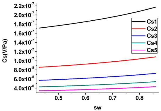
Figure 12.
Influence of viscosity on streaming potential coupling coefficient (slug flow).
It can be seen from Figure 3 and Figure 8 that, as the saturation decreases, the streaming potential coupling coefficient of the capillary first increases and then decreases. Figure 13 is a comparison between the simulation in this work and some experimental results in Ref. [14]. The black curve is the simulation result of this paper, and the blue points are part of the experimental result from Ref. [14]. The change trends with saturation are the same, which can prove the correctness of this work.
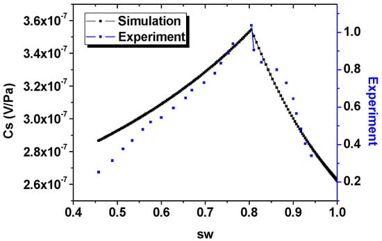
Figure 13.
Comparison between simulation and Allègre’s experiment.
4. Conclusions
At present, there is a lack of research on the seismoelectric effect of unsaturated porous media in the gas phase discrete case, and the existing theory does not consider the influence of the electric double layer at the gas–liquid interface on the electrokinetic effect [7,8,9,10,11,12,13]. In this work, we considered the influence of the electric double layer at the solid–water interface and the gas–water interface at the same time, and proposed the equivalent principle of series circuits to study the basic principle of the seismoelectric effect in the gas phase discrete pore under the excitation of a steady acoustic field. Through simulation and analysis, the following conclusions can be drawn:
- When the saturation is high, there is a bubbly flow in the pore. At this time, the streaming potential coupling coefficient is mainly affected by parameters such as saturation, bubble spacing, pore size, salinity, and viscosity. The bubble spacing and pore radius are positively correlated with the coupling coefficient of the capillary; saturation, salinity, and viscosity are negatively correlated with the coupling coefficient of the capillary.
- When the saturation gradually becomes smaller, there is a slug flow in the pore. At this time, the streaming potential coupling coefficient is mainly affected by parameters such as saturation, water film thickness, pore size, salinity, and viscosity. Among them, saturation and pore size are positively correlated with the coupling coefficient of the capillary; water film thickness, salinity, and viscosity are negatively correlated of the coupling coefficient of the capillary.
- With the decrease in saturation, the two-phase flow pattern in the pore changes from bubbly flow to slug flow, and the corresponding streaming potential coupling coefficient increases first and then decreases, which is the same as the change trend measured in Allègre’s experiments, and this work explains this phenomenon theoretically for the first time.
Author Contributions
Conceptualization, Y.Z. and X.S.; methodology, Y.Z; software, Y.Z; validation, Y.Z., X.S. and Z.N.; formal analysis, Y.Z.; investigation, Y.Z.; resources, Y.Z.; data curation, Y.Z., X.S. and Z.N.; writing—original draft preparation, Y.Z.; writing—review and editing, X.S. and Z.N.; visualization, X.S; supervision, Z.N.; project administration, Z.N.; funding acquisition, X.S. and Z.N. All authors have read and agreed to the published version of the manuscript.
Funding
The research is supported by the National Science Foundation of China (Grant No. 61727803).
Data Availability Statement
Data is unavailable due to privacy and ethical restrictions.
Conflicts of Interest
The authors declare no conflict of interest.
References
- Packard, R.G. Streaming potentials across glass capillaries for sinusoidal pressure. J. Chem. Phys. 1953, 21, 303–307. [Google Scholar] [CrossRef]
- Pride, S.; Morgan, F.D. On the importance of electrokinetic forces in the acoustics of porous media. In SEG Technical Program Expanded Abstracts; Society of Exploration Geophysicists: Houston, TX, USA, 1989; pp. 579–581. [Google Scholar]
- Pride, S.R.; Morgan, F.D. Electrokinetic dissipation induced by seismic waves. Geophysics 1991, 56, 914–925. [Google Scholar] [CrossRef]
- Pride, S. Governing equations for the coupled electromagnetics and acoustics of porous media. Phys. Rev. B 1994, 50, 15678. [Google Scholar] [CrossRef] [PubMed]
- Glover, P.W.; Déry, N. Streaming potential coupling coefficient of quartz glass bead packs: Dependence on grain diameter, pore size, and pore throat radius. Geophysics 2010, 75, F225–F241. [Google Scholar] [CrossRef]
- Glover, P.W.; Walker, E.; Jackson, M.D. Streaming-potential coefficient of reservoir rock: A theoretical model. Geophysics 2012, 77, D17–D43. [Google Scholar] [CrossRef]
- Wurmstich, B.; Morgan, F.D. Modeling of streaming potential responses caused by oil well pumping. Geophysics 1994, 59, 46–56. [Google Scholar] [CrossRef]
- Revil, A.; Schwaeger, H.; Cathles, L.M., III; Manhardt, P.D. Streaming potential in porous media: 2. Theory and application to geothermal systems. J. Geophys. Res. Solid Earth 1999, 104, 20033–20048. [Google Scholar] [CrossRef]
- Darnet, M.; Marquis, G. Modelling streaming potential (SP) signals induced by water movement in the vadose zone. J. Hydrol. 2004, 285, 114–124. [Google Scholar] [CrossRef]
- Perrier, F.; Morat, P. Characterization of electrical daily variations induced by capillary flow in the non-saturated zone. Pure Appl. Geophys. 2000, 157, 785–810. [Google Scholar] [CrossRef]
- Revil, A.; Cerepi, A. Streaming potentials in two-phase flow conditions. Geophys. Res. Lett. 2004, 31, 293–317. [Google Scholar] [CrossRef]
- Linde, N.; Jougnot, D.; Revil, A.; Matthäi, S.K.; Arora, T.; Renard, D.; Doussan, C. Streaming current generation in two-phase flow conditions. Geophys. Res. Lett. 2007, 34, L03306. [Google Scholar] [CrossRef]
- Slattery, J.C. Momentum, Energy, and Mass Transfer. Chem. Eng. Educ. 1972, 6, 174–197. [Google Scholar]
- Allègre, V.; Jouniaux, L.; Lehmann, F.; Sailhac, P. Streaming potential dependence on water-content in Fontainebleau sand. Geophys. J. Int. 2010, 182, 1248–1266. [Google Scholar] [CrossRef]
- Allegre, V.; Maineult, A.; Lehmann, F.; Lopes, F.; Zamora, M. Self-potential response to drainage–imbibition cycles. Geophys. J. Int. 2014, 197, 1410–1424. [Google Scholar] [CrossRef]
- Allègre, V.; Jouniaux, L.; Lehmann, F.; Sailhac, P.; Toussaint, R. Influence of water pressure dynamics and fluid flow on the streaming-potential response for unsaturated conditions. Geophys. Prospect. 2015, 63, 694–712. [Google Scholar] [CrossRef]
- Serizawa, A.; Feng, Z.; Kawara, Z. Two-phase flow in microchannels. Exp. Therm. Fluid Sci. 2002, 26, 703–714. [Google Scholar] [CrossRef]
- Sherwood, J.D. Streaming potential generated by two-phase flow in a capillary. Phys. Fluids 2007, 19, 053101. [Google Scholar] [CrossRef]
- Lac, E.; Sherwood, J.D. Streaming potential generated by a drop moving along the centreline of a capillary. J. Fluid Mech. 2009, 640, 55–77. [Google Scholar] [CrossRef]
- Sherwood, J.D.; Xie, Y.; van den Berg, A.; Eijkel, J.C. Theoretical aspects of electrical power generation from two-phase flow streaming potentials. Microfluid. Nanofluidics 2013, 15, 347–359. [Google Scholar] [CrossRef]
- Creux, P.; Lachaise, J.; Graciaa, A.; Beattie, J.K. Specific cation effects at the hydroxide-charged air/water interface. J. Phys. Chem. C 2007, 111, 3753–3755. [Google Scholar] [CrossRef]
- Ishido, T.; Mizutani, H. Experimental and theoretical basis of electrokinetic phenomena in rock-water systems and its applications to geophysics. J. Geophys. Res. Solid Earth 1981, 86, 1763–1775. [Google Scholar] [CrossRef]
- Sherwood, J.D. Electrophoresis of gas bubbles in a rotating fluid. J. Fluid Mech. 1986, 162, 129–137. [Google Scholar] [CrossRef]
- Takhistov, P.; Indeikina, A.; Chang, H.C. Electrokinetic displacement of air bubbles in microchannels. Phys. Fluids 2002, 14, 1–14. [Google Scholar] [CrossRef]
- Bretherton, F.P. The motion of long bubbles in tubes. J. Fluid Mech. 1961, 10, 166–188. [Google Scholar] [CrossRef]
- Keh, H.J.; Liu, Y.C. Electrokinetic flow in a circular capillary with a surface charge layer. J. Colloid Interface Sci. 1995, 172, 222–229. [Google Scholar] [CrossRef]
Disclaimer/Publisher’s Note: The statements, opinions and data contained in all publications are solely those of the individual author(s) and contributor(s) and not of MDPI and/or the editor(s). MDPI and/or the editor(s) disclaim responsibility for any injury to people or property resulting from any ideas, methods, instructions or products referred to in the content. |
© 2022 by the authors. Licensee MDPI, Basel, Switzerland. This article is an open access article distributed under the terms and conditions of the Creative Commons Attribution (CC BY) license (https://creativecommons.org/licenses/by/4.0/).