Abstract
Planetary gearboxes have been employed in various applications due to their advantages of maintaining a high speed-reduction ratio, such as in wind power applications which have now become a prevailing green energy resource. A traditional power transmission machine of the wind turbine has a fixed gear-ratio mechanical gearbox for speed-increasing transmission. The purpose of this study is to propose an active continuous variable transmission (ACVT) control system with a planetary gear to apply to the wind turbine. The planetary gear holds three terminals, i.e., the ring gear, the planet carrier, and sun gear, and the motions of three terminals can be controlled purposely by the servomotors to achieve ACVT. The three different transmission types of the proposed ACVT can be operated. The dynamic characteristic of the planetary gear is expressed in block diagram form, and a pseudo derivative feedback feed-forward controller of the velocity control loop is designed for the required performance. The results can be used to verify the effect of the proposed ACVT with the planetary gear.
1. Introduction
The planetary gear set is a gear structure with small size, light weight, high transmission efficiency and large load capacity, which can meet the requirements of high efficiency and miniaturization of gear transmission. Planetary gears are widely used in different mechanical structures, such as aircraft transmission systems, automobile engines, and bicycle transmissions, as well as heavy-duty and high-reduction-ratio machines. The planetary gear system includes the outer ring gear, the sun gear, the planetary gear, and the planetary arm shaft. Since the sun gear and the ring gear can decelerate relative to the planet carrier, if the planet carrier is used as the input port, this acceleration behavior due to the increased speed can be used to provide the appropriate inertia. Different from the previous single input and single output system, another feature of the planetary gear system is that it is a three-terminal device. Therefore, when the planetary gear train is running, the planetary gear has two motion states of rotation and revolution, so the calculation method of its transmission ratio is different from that of the fixed-axis gear transmission mechanism. In order to calculate the transmission ratio of the planetary gear mechanism, the single planetary gear mechanism is first analyzed. For the calculation method of the transmission ratio of the gear mechanism, because in the single planetary gear mechanism, the planetary gear is only the role of the intermediate gear, i.e., idler gear, the transmission ratio of the planetary gear mechanism depends on the sun gear and the ring gear. Therefore, the transmission ratio of the planetary gear mechanism depends on the sun gear and the ring gear.
In corresponding works in the literature, the many studies of the continuous variable transmission with planetary gear can be found. Ref. [1] proposed a torsional vibration dynamic model of a compound planetary power-split hybrid electric vehicle to predict the torsional vibration. Ref. [2] proposed an electromechanical power-splitting full-hybrid transmission with two shifting elements, where a four-shaft planetary gear and an electronic continuously variable transmission were analyzed. Ref. [3] proposed the singular point transition concept relating a novel type of continuously variable transmission. This transmission comprises a pair of planetary gear trains and a couple of electric motors, used to control the overall speed ratio. Ref. [4] proposed a standard modeling process, which can be used to model the complicated vehicle planetary gearbox and can be used to study the automatic transmission control and failure diagnostic. Ref. [5] proposed a new robust speed control to suppress vibration caused by angular transmission error of planetary gears. A new numerical simulation model of angular transmission error of planetary gear was expressed. Ref. [6] proposed a magnetorheological-fluid-based planetary gear transmission, which serves to variably couple the motor power through a sun gear input to a load affixed to a planet carrier output. Ref. [7] proposed a fuel control system on a planetary automatic transmission to control gear shifts based on the level of the road slope. A planetary gear-based transmission system for the power-assisted bike (PAB) was proposed in [8] because of its appealing 2-input/1-output transmission feature. Considering the practical requirements for power assistance, the electronically controlled continuously variable transmission and the torque assistance modes were realized for the PAB system. Ref. [9] presented a design approach to systematically synthesize feasible configurations for series–parallel and parallel hybrid transmissions subject to design constraints and required operation modes, using a simple planetary gear train. Ref. [10] presented a comparative study of hybrid powertrains with different numbers of planetary gear sets. The results show that triple-planetary gear hybrids do not have significant fuel economy improvement, compared with double-planetary gear hybrids, but they achieve a dramatic improvement in acceleration performance; this can be beneficial for sport utility vehicles, light trucks, and buses. Ref. [11] proposed a novel design of a dual actuator unit composed of two actuators and a planetary gear train to provide the capability of simultaneously controlling position and stiffness. An energy-compensated fuzzy swing-up and balance control was investigated by [12] for the planetary-gear-type inverted pendulum. The proposed control scheme consists of a fuzzy swing-up controller, a fuzzy sliding balance controller, and a fuzzy compensation mechanism. Ref. [13] proposed an actuator system for mobile robot applications. The actuator system consists of dual motors and a planetary gear, which improves the speed–torque performance by combining two motors with one planetary gear. Ref. [14] proposed a methodology for model-based fault diagnostics of planetary gears using transmission error signals. A lumped parametric model of planetary gear dynamics was built to extract simulated transmission error signals, while accounting for the planet phasing effect, which is a peculiar characteristic of the planetary gear. An approach for tooth localized fault detection in the sun gear of a planetary gear, using the measured mechanical torque and the stator current of a wound rotor induction generator (WRIG), was proposed in [15]. A theoretical background is developed to demonstrate that the faulty sun gear produces periodic fault signatures in the mechanical torque and, consequently, fault-related frequencies in the stator current of the WRIG. Ref. [16] proposed a novel design by integrating a planetary gear train within a brushless DC motor to be a compact structure assembly. It provides functional and structural integrations to overcome the inherent disadvantages of the traditional designs. Ref. [17] proposed a tacholess order tracking method based on adaptive instantaneous angular speed estimation for wind turbine planetary gearbox fault diagnosis. Ref. [18] developed a regenerative braking method for transient torsional oscillation suppression of a planetary-gear electrical powertrain. An angle-varying mesh stiffness-considered transmission model and a genetic algorithm-based method were proposed for the allocation of electric regenerative braking torque. In [19], nonlinear dynamics of two-stage planetary gear system with elastic ring gear and sliding friction were studied. The effect of sliding friction and the ring’s elasticity was given on the nonlinear behavior through the previous elastic two-stage planetary gear system model. Ref. [20] focused on compound planetary gears, and the bending–torsion coupling nonlinear dynamic model of the system based on the Lagrange equation was developed. This model is used to study the bending–torsion coupling meshing deformation relationship of each meshing pair along with the translational and torsional directions. Ref. [21] investigated the driving torque control strategies of the planetary-gear-based dual motor powertrain. The rigid dynamic model of the powertrain was given to formulate a general energy management strategy (EMS) and a proposed robust EMS was used to avoid the drastic change of the motors speed. In [22], applied to a 1.5 MW wind turbine planetary gear system, a two-parameter Weibull distribution model to describe the distribution of random wind speed was constructed by using the lumped parameter method, and the relative relations among various components were derived by using the Lagrange method. Ref. [23] described the precise plant model of the two-link manipulator with the bi-articular muscle. By using this model, the interference between mono-articular and bi-articular muscles is compensated. In [24], a theoretical design methodology for hybrid electric vehicle powertrain configurations with planetary gear set was proposed to find the configurations with excellent performance in a large pool of configurations. A novel matrix representation method was developed to express these kinds of connections to reflect the system dynamics and physical structure of configurations. In [25], a dual-motor solution was proposed, where two smaller motors are coupled via a planetary gear, in contrast to the standard configuration that uses one larger motor directly connected to the drive wheels with a fixed ratio reducer. The dual-motor architecture guarantees that both motors operate in the vicinity of their optimal working range, resulting in a higher overall energy efficiency.
In general power applications, the planetary gears are regarded as passive components, so their applications are relatively limited. Therefore, this paper proposes an active continuous variable transmission (ACVT) control system with planetary gears. The control system is mainly through the connection between the servo motors and the gears, using the three gears (sun gear, planetary carrier, and ring gear) as the control system with two inputs and one output, through the coordinated control of the gear motion information (such as torque and angular velocity) and the coordinated control of the motor’s angular velocity/torque. Based on the proposed ACVT control method, the planetary gear has both the variable equivalent inertia and the controllable velocity ratio between the gears; the dynamic speed ratio varying effect can be achieved without multi-stage transmission. Compared with the traditional continuous variable transmission, the transmission efficiency of the proposed ACVT system with the planetary gear can be greatly improved.
In this paper, an active transmission motion control system is proposed that appropriately stably regulates the speed of a generator. At each terminal of the mechanical gear sets, the revealed tangent–velocity equations are utilized to plot the block diagram. A method to analyze the kinematic equations and their block diagram for the planetary gear is described. The feedback and feedforward in control are exported to illustrate the speed-reduction and -increasing function in kinematics. Observing the accordance between control methods and kinematics, the paper provides another view for other field engineers to understand the mechanical design thinking.
2. Material and Method
This paper proposes an active continuous variable transmission (ACVT) control system with planetary gears, as shown in Figure 1. The motor_r is connected to the ring gear, where , , and are the torque, angular acceleration, and angular velocity of the ring gear/motor_r, respectively. The motor_s is connected to the sun gear, where , , and are the torque, angular acceleration, and angular velocity of the sun gear/motor_s, respectively. The motor_p is connected to the planetary arm shaft, where , , and are the torque, angular acceleration, and angular velocity of the planet carrier/motor_c, respectively. The control system is mainly through the connection between the servo motors and the gears, using the three gears (sun gear, planetary carrier, and ring gear) as the control system with two inputs and one output through the coordinated control of the gear motion information (such as torque and angular velocity) and the coordinated control of the motor’s angular velocity/torque.
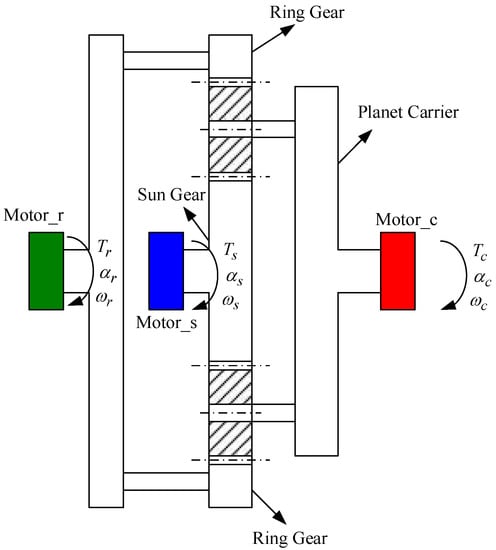
Figure 1.
Proposed planetary gear with three terminals.
2.1. Analysis of Continuous Variable Transmission Control System
The transmission equation of the planetary gear is given as (1), then its motion block diagram can be shown in Figure 2.
where is the teeth number of the ring gear, and is the teeth number of the sun gear. The torque relationship between the gears of the planetary gear is given as (2).
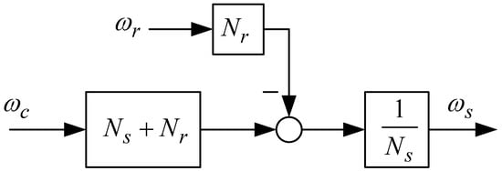
Figure 2.
Motion block diagram of the planetary gear.
According to the kinematic characteristic equation of the single planetary gear mechanism, it can be seen that among the three basic elements of the sun gear, the outer ring gear, and the planet carrier, two of the basic elements can be selected as the input (driving gear) and the output (driven gear). The other gear can be fixed. The transmission ratio of the mechanism can be calculated, and the various possible situations are discussed below.
2.1.1. Reduction Drive
For the case of the fixed ring gear, i.e., , the sun gear is the input port and the planet carrier is the output port. Then we have
Due to the number of the ring gear teeth being larger than that of the sun gear, i.e., , can be smaller than 1. Therefore, the transmission characteristic of the planetary gear is given as a reduction drive of the reducing velocity and increasing torque. For the case of the fixed sun gear, i.e., , the ring gear is the input port, and the planet carrier is the output port. Then we have
It can be found that ; therefore, the transmission is also a reduction drive with reducing velocity and increasing torque. For the case of the fixed planet carrier, i.e., , the sun gear is the input port, and the ring gear is the output port. In this situation, the planetary gear performs only self-rotation, but struggles with revolution around the sun gear. Then we can obtain
It can be found that ; therefore, the transmission is the reduction drive with reducing velocity and increasing inverse torque.
2.1.2. Increasing Drive
For the case of the fixed sun gear, i.e., , the planet carrier is the input port, and the ring gear is the output port. Then we can have
Due to , the velocity of the ring gear is larger than that of the planet carrier, i.e., ; therefore, the transmission increases the drive with the increasing velocity and reducing torque. For the case of the fixed ring gear, i.e., , the planet carrier is the input port, and the sun gear is the output port. Then we have
It can be found that ; therefore, the transmission is increasing velocity and reducing torque. For the case of the fixed planet carrier, i.e., , the ring gear is the input port, and the sun gear is the output port. We have then
The transmission of the case is increasing velocity and reducing inverse torque.
In this paper, the control block diagram of the planetary gear is constructed to analyze the dynamic characteristics of the transmission of the planetary gear.
From the above motion analysis of the cases, to consider the practical application, the planet carrier is the input port, the sun gear is the output port, and the ring gear can be represented as the control port, i.e., being controllable. Then we have , where is a designed feedforward gain. Its motion control block control diagram can be given as shown in Figure 3.
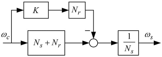
Figure 3.
Motion control block diagram of the planetary gear with feedforward gain .
From Figure 3, we can obtain
Taking the wind turbine as an example, as , the ring gear is fixed () and the wind turbine is accelerating; while , the sun gear is accelerating, which can be used to reduce the sudden wind power in the turbine. As , the sun gear can be decelerated, which can be used to increase the velocity of the wind turbine with weak wind power.
In practical application, the proposed technology can generate varying velocities of the gears so as to analyze the equivalent inertia of the planetary gear with differential inputs and outputs (for example, from the sun gear to the planet carrier or the ring gear to the sun gear, etc.), through the speed coordination of the motor control, and then achieve the purpose of controllable equivalent inertia. Considering the velocity-increasing function of the wind turbine, its input can be given by the planet carrier, and the velocity and rotation direction of the ring are controlled by the motor. The sun gear shaft is connected to the load, such as the flywheel, and the velocity of the sun gear shaft can be variable to produce a function of controllable inertia. The proposed control system is expected to be applied to different industries, such as precision machinery stabilizers and shock absorbers.
From the operating characteristics of the ACVT control system, the ring gear connected to the motor is controlled to turn in the same direction as the planet carrier, and the input power of the planet carrier can be rebounded. The planet carrier is very difficult to be rotated, which may eventually cause the planet carrier to stop or reverse. For the rotation direction of the ring gear being opposite to that of the planet carrier, the planet carrier can be easy rotated, so the power input from the outside can be easily absorbed, and finally the sun gear may stop and reverse.
In power transmission applications, the continuous variable transmission system can provide continuous variable velocity to generate smooth power transmission. The continuously variable transmission system used in vehicles is classified by belt type, disc type, cone type, crank type, cam type, planetary gear type, and friction wheel type. As shown in Figure 4a, this is a typical belt-type continuously variable transmission system. The main components are composed of a driving wheel disc, driven wheel disc and transmission belt. The driving wheel disc is composed of a fixed driving disc, a sliding driving disc, a swash plate, a sliding sheet, a centrifugal roller, and a sliding sleeve. In Figure 4a, , , and are the equivalent inertia, rotation velocity, and torque of the input port, respectively, while , , and are equivalent inertia, rotation velocity, and torque of the output port, respectively. is the loading torque. Then, the motion equation of the belt-type continuously variable transmission is given as (10).
where is the reduction ratio. Then, (10) can be rewritten as (11), and its block diagram is shown in Figure 4b. Note that is the operator of the Laplace transformation.
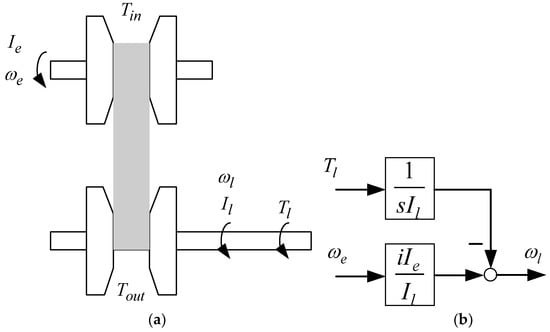
Figure 4.
(a) Belt-type continuously variable transmission system and (b) its block diagram.
Figure 5 is the belt-type continuously variable transmission device with the planetary gear. The ring gear is the input port, and the planetary arm shaft is the output port. The sun gear is connected to the flywheel. and are the equivalent inertia and rotation velocity of the flywheel. Note that , , and can be found. The motion equation of the control system in Figure 5a can be given as (12), and its block diagram is shown in Figure 5b.
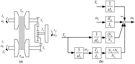
Figure 5.
(a) Belt-type continuously transmission device with the planetary gear (Type 1) and (b) its block diagram.
For the continuously variable transmission of Figure 5 applied to vehicles, the motion characteristics of (12) are discussed. Assume that the ring gear is connected to the engine. As the rotation velocity of the engine is increased, the angular velocity of the flywheel can be reduced, which is similar to reducing the equivalent inertia of the engine. As the rotation velocity of the engine is reduced, the rotation velocity of the flywheel can be increased, i.e., the corresponding power being absorbed by the flywheel, which is similar to increasing the equivalent inertia of the engine.
Figure 6a is another type of the belt-type continuously variable transmission device with the planetary gear. The input port of the belt-type continuously variable transmission device is connected to the sun gear, while the output port of the belt-type continuously variable transmission device is connected to the ring gear. Therefore, the motion equation of Figure 6a can be given as (13), and its block diagram is shown in Figure 6b.
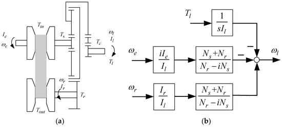
Figure 6.
(a) Belt-type continuous transmission device with the planetary gear (Type 2) and (b) its block diagram.
For the operation of the low velocity and high torque, most of the energy is provided by the input end (the sun gear) of the belt-type continuously variable transmission, and the output is through the planetary arm. For operation at high velocity and low torque, the energy can be provided by the output end (the ring gear), and through the control of the reduction ratio of the belt-type continuously variable transmission, high-efficiency continuously variable speed operation can be achieved.
2.2. Dynamic Analysis of the Planetary Gear
This paper studies the dynamic characteristics of the ACVT of the planetary gear and aims at the influence of the variable of the motor torque and velocity on the external input (the planet carrier). By analyzing the influence, the relationship between the torque and the angular velocity between the sun gear and the planet carrier can be established. In this study, the ACVT system is used to actively adjust the reduction ratio of the planetary gear control system so that the transmission system can be maintained at the optimal operating point to improve transmission efficiency and control performance. According to Newton’s law of motion, the concept of free body diagram and dynamic balance is applied to the rigid body plane motion to discuss the mathematical model of the planetary gear and further deduce the dynamic characteristic equation. In order to achieve the purpose of acceleration and deceleration, the analysis of the transmission mode of the planetary gear train is carried out, and the ACVT system is achieved through the velocity control of the servo motor. Figure 7 shows the dynamic characteristics of the planetary gear, where and are the equivalent stiffness and damping coefficients between the ring gear and planetary gear, respectively, while and represent those of the sun gear and the planetary gear, respectively.
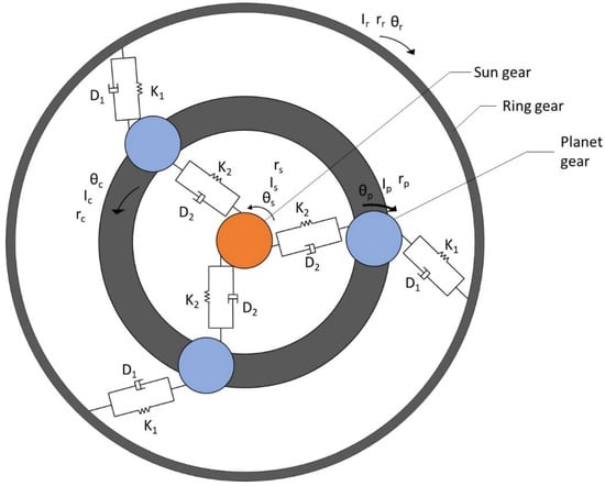
Figure 7.
Dynamic characteristics of the planetary gear.
Based on Figure 8, the kinetic characteristics of the gears are analyzed, and their dynamic equations can be exported. For the ring gear, the dynamic characteristic equation can be given as (14). The Laplace transformation of (14) is obtained as (15).
where is the Laplace operator; , , , and are the Laplace transformations of , , , and , respectively.
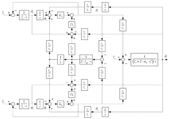
Figure 8.
Block diagram of the planetary gear.
For the sun gear, its dynamic equation can be given as (16). Its Laplace transformation is given as (17).
For the planetary gear, its dynamic equation can be given as (18). Its Laplace transformation is given as (19).
For the planet carrier, its dynamic equation can be given as (20). The Laplace transformation of (20) is given as (21).
where , , , , and are given. , , and are defined as the self-inertia, integrated inertia, and mass of the planetary gear. and are the radius and the equivalent inertia of the planet carrier. is the number of planetary gears. Note that is given in this case. Based on (15), (17), (19), and (21), the block diagram of the planetary gear control system can be given as Figure 8.
3. Results Analysis
In the experiment as shown in Figure 9, three 1400 watt servomotors are given to be connected to the planetary gear, where the angular velocity is calculated by the encoder, and the torque is measured by the torque meter. In this control system, two input ports and one output port are given. Therefore, the motions of the two gears can be controlled to the required motion output of another gear to achieve the ACVT system. Three motion types of the planetary gear system are given to verify the effect of the proposed method. The specifications of the planetary gear are given in Table 1, as shown. The corresponding parameters of the plenary gear are determined by the software CATIA.
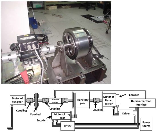
Figure 9.
Experimental setup of the proposed ACVT system.

Table 1.
Specifications of the planetary gear.
In this paper, the velocity control loop of the servomotor is designed for regulating the required angular velocities of the gears, where is the motor reference input of the angular velocity, is the angular velocity output of the gear motor, and is the disturbance from the mechanical coupling of the planetary gear set. The motor’s parameters of , , and are obtained. A pseudo derivative feedback feed-forward controller (see Figure 10) is proposed for the required performance, where the control parameters of , , and can be designed. Let the bandwidth of the velocity loop be set to 40 Hz, which is just for the general requirement of the motion control performance.
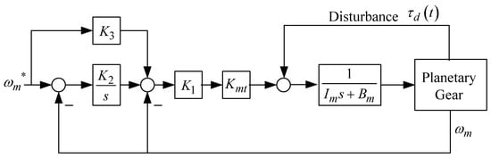
Figure 10.
Block diagram of velocity loop control system for the servomotor.
For the control system of Figure 10, the transfer function of the velocity control loop with can be given as
where and can be determined for the form of a standard second order control system. In this case, the loop bandwidth and the damping ratio are pre-determined. Therefore, the control parameters of and can be calculated. The feedforward control gain is determined in this case to improve control performance. As shown in Figure 11, three kinds of motion planning are used to analyze the dynamic characteristics of the proposed planetary gear, where the three servomotors of the motor_s, the motor_p, and the motor_r are connected to the sun gear, the planet carrier, and the ring gear, respectively. For each type, two motors connected to the gears can be used to be the inputs and another one motor is given as the load for the gear. A modeling verified experiment is given, where the S-curve velocity command with maximum velocity 600 rpm and maximum acceleration 20 is designed. Based on the control system in Figure 10, the angular velocity responses of the planet carrier motor and ring gear motor are measured as shown in Figure 12 and Figure 13, respectively, where the maximum velocity error about can be found. For observing the torque output performance of the planet carrier under varying velocity of the ring gear motor, an S-curve velocity command of the planet carrier is given as the maximum velocity of 600 rpm and maximum acceleration of 20 and an S-curve velocity command of the ring gear motor is given as the maximum velocity of 1500 rpm and maximum acceleration of 50 . Figure 14 shows the torque response of the planet carrier motor with varying angular velocity of the ring gear motor. It can be found that the torque outputs of the planet carrier are ±17.5 Nm and 12.5 Nm~−10 Nm with 1500 rpm and 0 rpm of the ring gear, respectively.
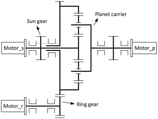
Figure 11.
Proposed ACVT control system with the planetary gear driven by motors.
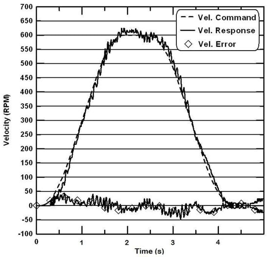
Figure 12.
Angular velocity response of the planet carrier motor.
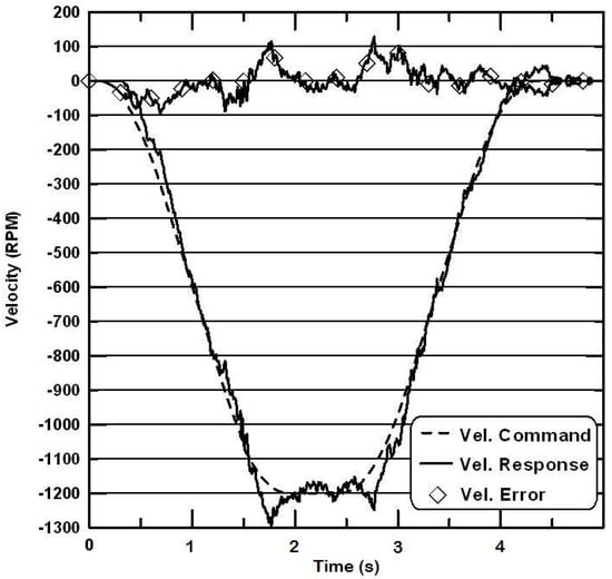
Figure 13.
Angular velocity response of the ring gear motor.
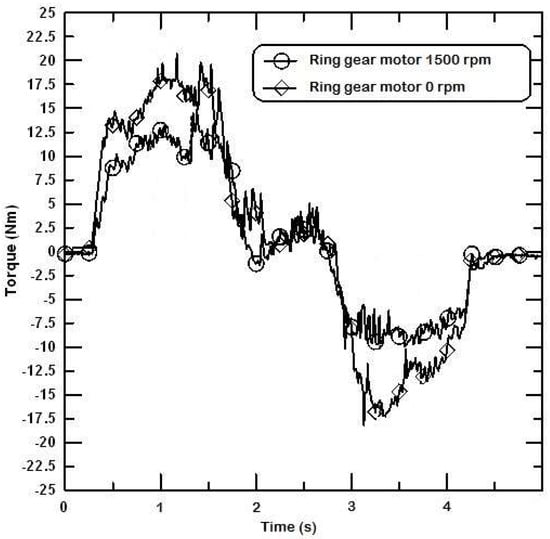
Figure 14.
Torque response of the planet carrier motor with varying angular velocity of ring gear motor.
In the experimental setup for this ACVT control system, two input ports and one output port are given. The motions of the two gears can be controlled to the required motion output of another gear to achieve the ACVT system. The simulated and experimental results for the responses of the velocity and torques are shown in Figure 15, Figure 16, Figure 17, Figure 18, Figure 19, Figure 20, Figure 21, Figure 22, Figure 23, Figure 24, Figure 25 and Figure 26. For case 1, the sun gear and the ring gear are given as the input ports, and the planet carrier is the output port. The results are shown in Figure 15, Figure 16, Figure 17 and Figure 18. From the results, the characteristics of the high angular velocity and high angular acceleration can be found. Varying the angular velocity alone of the ring gear can be used to generate the output of the larger angular acceleration or deceleration of the planet carrier, while that of the planet carrier is smaller with only varying the angular velocity of the sun gear. The outputs of the angular velocity and torque of the planet carrier are larger than those of the traditional gear reducer.
Figure 15.
Simulated results for velocity output of the planet carrier with the velocity inputs of the ring and the sun gears.
Figure 16.
Experimental results for velocity output of the planet carrier with the velocity inputs of the ring and the sun gears.
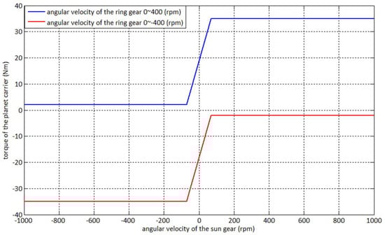
Figure 17.
Simulated results for torque output of the planet carrier with the velocity inputs of the ring and the sun gears.
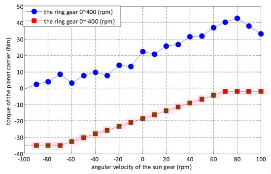
Figure 18.
Experimental results for torque output of the planet carrier with the velocity inputs of the ring and the sun gears.
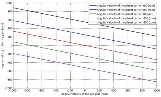
Figure 19.
Simulated results for velocity output of the ring gear with the velocity inputs of the planet carrier and the sun gear.
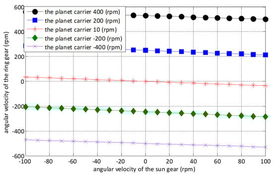
Figure 20.
Experimental results for velocity output of the ring gear with the velocity inputs of the planet carrier and the sun gear.
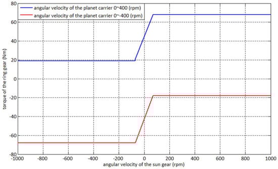
Figure 21.
Simulated results for torque output of the ring gear with the velocity inputs of the planet carrier and the sun gear.
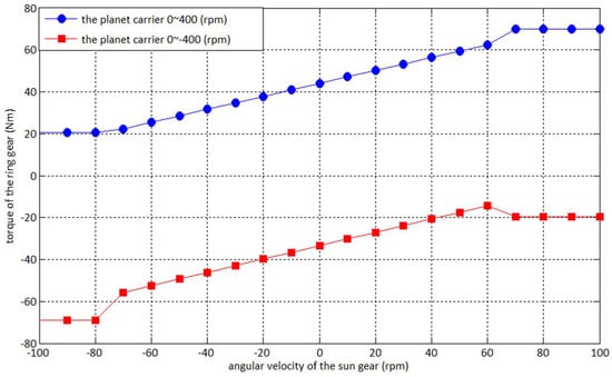
Figure 22.
Experimental results for velocity output of the ring gear with the velocity inputs of the planet carrier and the sun gear.
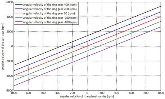
Figure 23.
Simulated results for velocity output of the sun gear with the velocity inputs of the planet carrier and the ring gear.
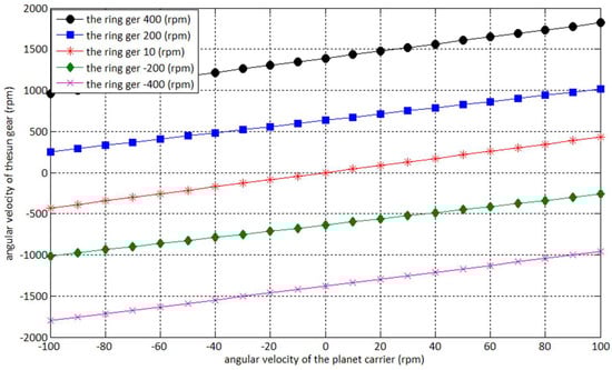
Figure 24.
Experimental results for velocity output of the sun gear with the velocity inputs of the planet carrier and the ring gear.
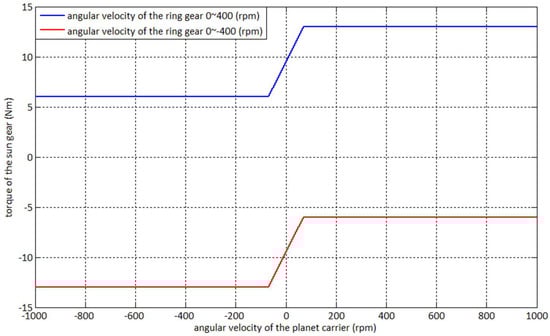
Figure 25.
Simulated results for torque output of the sun gear with the velocity inputs of the planet carrier and the ring gear.
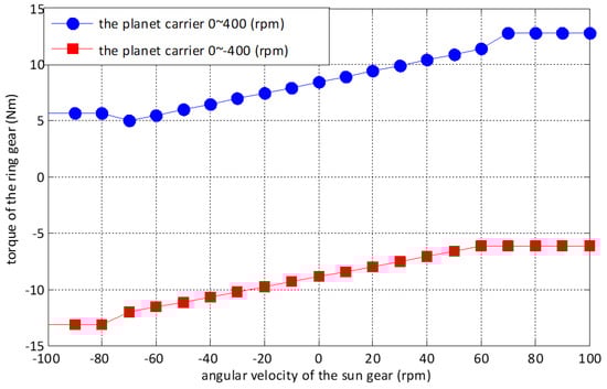
Figure 26.
Experimental results for torque output of the ring gear with the velocity inputs of the planet carrier and the sun gear.
For case 2, the sun gear and the planet carrier are the input ports, and the ring gear is the output port. The results are shown in Figure 19, Figure 20, Figure 21 and Figure 22. Observing the results, the characteristics of the high angular velocity and low angular acceleration (low angular velocity and high angular acceleration) can be found. Only varying the angular velocity of the planet carrier can be used to generate the output of the larger angular acceleration or deceleration of the ring gear, while that of the ring gear is smaller with only varying the angular velocity of the sun gear. The outputs of the angular velocity and torque of the ring gear are larger than those of the traditional gear reducer.
For case 3, the ring gear and the planet carrier are the input ports, and the sun gear is the output port. The results are shown in Figure 23, Figure 24, Figure 25 and Figure 26. Observing the results, with the rotation directions of the ring gear and the planet carrier being the same, the characteristics of the high angular velocity and high torque can be found. Otherwise, with the rotation directions of the ring gear and the planet carrier being different, the high angular velocity and low torque can be found. Only varying the angular velocity of the ring gear can be used to generate the larger angular acceleration or deceleration of the sun gear, while that of the ring gear is smaller with only varying the angular of the planet carrier. The outputs of the angular velocity and torque are larger than those of the traditional gear reducer.
4. Conclusions
The paper proposed an active continuous variable transmission (ACVT) control system with planetary gear. The planetary gear holds three terminals, i.e., the ring gear, the planet carrier, and sun gear, and the motions of the three terminals can be controlled deliberately by the servomotors to achieve ACVT. The three different transmission types of the proposed ACVT can be operated. The dynamic characteristic of the planetary gear is expressed in block diagram form and a pseudo derivative feedback feed-forward controller of the velocity control loop is designed for the required performance. From the results, through the proposed the planetary gear control system, the characteristics of the high angular velocity and high angular acceleration can be achieved. Varying synchronously the angular velocities of the ring gear and the sun gear, the output of the angular acceleration or deceleration of the planet carrier is larger, while that of the planet carrier is smaller with only varying the angular velocity of the sun gear or only varying the ring gear. Therefore, under three terminal ports, where one is the input port and the second is the output, the third can be used to be a controllable port to achieve the required motion performance. The results can be used to verify the effect of the proposed ACVT with the planetary gear.
Author Contributions
Conceptualization, W.-S.Y. and C.-Y.L.; methodology, W.-S.Y.; soft-ware, C.-Y.L.; validation, C.-Y.L.; formal analysis, W.-S.Y.; investigation, W.-S.Y.; resources, C.-Y.L.; data curation, C.-Y.L.; writing—original draft preparation, C.-Y.L.; writing—review and editing, W.-S.Y.; visualization, C.-Y.L. and W.-S.Y.; supervision, W.-S.Y. All authors have read and agreed to the published version of the manuscript.
Funding
This research received no external funding.
Conflicts of Interest
The authors declare no conflict of interest.
References
- Tang, X.; Zhang, J.; Zou, L.; Yu, H.; Zhang, D. Study on the torsional vibration of a hybrid electric vehicle powertrain with compound planetary power-split electronic continuous variable transmission. Proc. Inst. Mech. Eng. Part C J. Mech. Eng. Sci. 2014, 228, 3107–3115. [Google Scholar] [CrossRef]
- Yu, H.S.; Zhang, J.W.; Zhang, T. Control strategy design and experimental research on a four-shaft electronic continuously variable transmission hybrid electric vehicle. Proc. Inst. Mech. Eng. Part D J. Automob. Eng. 2012, 226, 1594–1612. [Google Scholar] [CrossRef]
- Ayats, J.R.G.; Diego-Ayala, U.; Artes, F.F. The singular point transition concept: A novel continuously variable transmission comprising planetary gear trains and a variator. J. Power Sources 2012, 197, 125–135. [Google Scholar] [CrossRef]
- Li, X.; Wang, A. A modularization method of dynamic system modeling for multiple planetary gear trains transmission gearbox. Mech. Mach. Theory 2019, 136, 162–177. [Google Scholar] [CrossRef]
- Miyazaki, T.; Ohishi, K. Robust speed control system considering vibration suppression caused by angular transmission error of planetary gear. IEEE/ASME Trans. Mechatron. 2002, 7, 235–244. [Google Scholar] [CrossRef]
- Christie, M.D.; Sun, S.; Quenzer-Hohmuth, J.; Deng, L.; Du, H.; Li, W.H. A magnetorheological fluid based planetary gear transmission for mechanical power-flow control. Smart Mater. Struct. 2021, 30, 045013. [Google Scholar] [CrossRef]
- Munahar, S.; Purnomo, B.C.; Köten, H. Fuel control systems for planetary transmission vehicles: A contribution to the LPG-fueled vehicles community. Mech. Eng. Soc. Ind. 2021, 1, 14–21. [Google Scholar] [CrossRef]
- Chen, C.L.; Wang, C.C.; Tsai, M.C.; Ko, P.J. Control system design of power assisted bike based on planetary gear. In Proceedings of the 2019 First International Symposium on Instrumentation, Control, Artificial Intelligence, and Robotics (ICA-SYMP), Bangkok, Thailand, 16–18 January 2019; pp. 171–174. [Google Scholar]
- Ngo, H.T.; Yan, H.S. Novel configurations for hybrid transmissions using a simple planetary gear train. J. Mech. Robot. 2016, 8, 021020. [Google Scholar] [CrossRef]
- Zhuang, W.; Zhang, X.; Ding, Y.; Wang, L.; Hu, X. Comparison of multi-mode hybrid powertrains with multiple planetary gears. Appl. Energy 2016, 178, 624–632. [Google Scholar] [CrossRef]
- Kim, B.; Song, J.; Park, J. A serial-type dual actuator unit with planetary gear train: Basic design and applications. IEEE/ASME Trans. Mechatron. 2010, 15, 108–116. [Google Scholar]
- Chang, Y.; Chang, C.; Taur, J.; Tao, C. Fuzzy swing-up and fuzzy sliding-mode balance control for a planetary-gear-type inverted pendulum. IEEE Trans. Ind. Electron. 2009, 56, 3751–3761. [Google Scholar] [CrossRef]
- Lee, H.; Choi, Y. A new actuator system using dual-motors and a planetary gear. IEEE/ASME Trans. Mechatron. 2012, 17, 192–197. [Google Scholar] [CrossRef]
- Park, J.; Ha, J.M.; Oh, H.; Youn, B.D.; Choi, J.-H.; Kim, N.H. Model-based fault diagnosis of a planetary gear: A novel approach using transmission error. IEEE Trans. Reliab. 2016, 65, 1830–1841. [Google Scholar] [CrossRef]
- Marzebali, M.H.; Faiz, J.; Capolino, G.; Kia, S.H.; Henao, H. Planetary gear fault detection based on mechanical torque and stator current signatures of a wound rotor induction generator. IEEE Trans. Energy Convers. 2018, 33, 1072–1085. [Google Scholar] [CrossRef]
- Yan, H.S.; Wu, Y.C. A novel design of a brushless DC motor integrated with an embedded planetary gear train. IEEE/ASME Trans. Mechatron. 2006, 11, 551–557. [Google Scholar] [CrossRef]
- Wang, Y.; Tang, B.; Meng, L.; Hou, B. Adaptive estimation of instantaneous angular speed for wind turbine planetary gearbox fault detection. IEEE Access 2019, 7, 49974–49984. [Google Scholar] [CrossRef]
- Wang, F.; Ye, P.; Xu, X.; Cai, Y.; Ni, S.; Que, H. Novel regenerative braking method for transient torsional oscillation suppression of planetary-gear electrical powertrain. Mech. Syst. Signal Processing 2022, 163, 108187. [Google Scholar] [CrossRef]
- Liu, W.; Shi, K.; Tupolev, V.; Yu, G.; Dai, B. Nonlinear dynamics of a two-stage planetary gear system with sliding friction and elastic continuum ring gear. J. Mech. Sci. Technol. 2022, 36, 77–85. [Google Scholar] [CrossRef]
- Cui, T.; Li, Y.; Zan, C.; Chen, Y. Dynamic modeling and analysis of nonlinear compound planetary system. Machines 2022, 10, 31. [Google Scholar] [CrossRef]
- Wu, J.; Zhang, N. Driving mode shift control for planetary gear based dual motor powertrain in electric vehicles. Mech. Mach. Theory 2021, 158, 104217. [Google Scholar] [CrossRef]
- Yang, H.; Li, X.; Xu, J.; Yang, Z.; Chen, R. Dynamic characteristics analysis of planetary gear system with internal and external excitation under turbulent wind load. Sci. Prog. 2021, 104, 1–21. [Google Scholar] [CrossRef] [PubMed]
- Nishimura, T.; Motoi, N. Motion control method based on two-link manipulator model with bi-articular muscle considering planetary gear. In Proceedings of the 2021 IEEE International Conference on Mechatronics, Kashiwa, Japan, 7–9 March 2021; pp. 1–6. [Google Scholar]
- Jiang, X.; Hu, J.; Peng, H.; Chen, Z. A design methodology for hybrid electric vehicle powertrain configurations with planetary gear sets. J. Mech. Des. 2021, 143, 083402. [Google Scholar] [CrossRef]
- Mantriota, G.; Reina, G. Dual-motor planetary transmission to improve efficiency in electric vehicles. Machines 2021, 9, 58. [Google Scholar] [CrossRef]
Publisher’s Note: MDPI stays neutral with regard to jurisdictional claims in published maps and institutional affiliations. |
© 2022 by the authors. Licensee MDPI, Basel, Switzerland. This article is an open access article distributed under the terms and conditions of the Creative Commons Attribution (CC BY) license (https://creativecommons.org/licenses/by/4.0/).