
Python-Based TinyIPFIX in Wireless Sensor Networks


Abstract
:1. Introduction
2. Related Work
2.1. TinyIPFIX
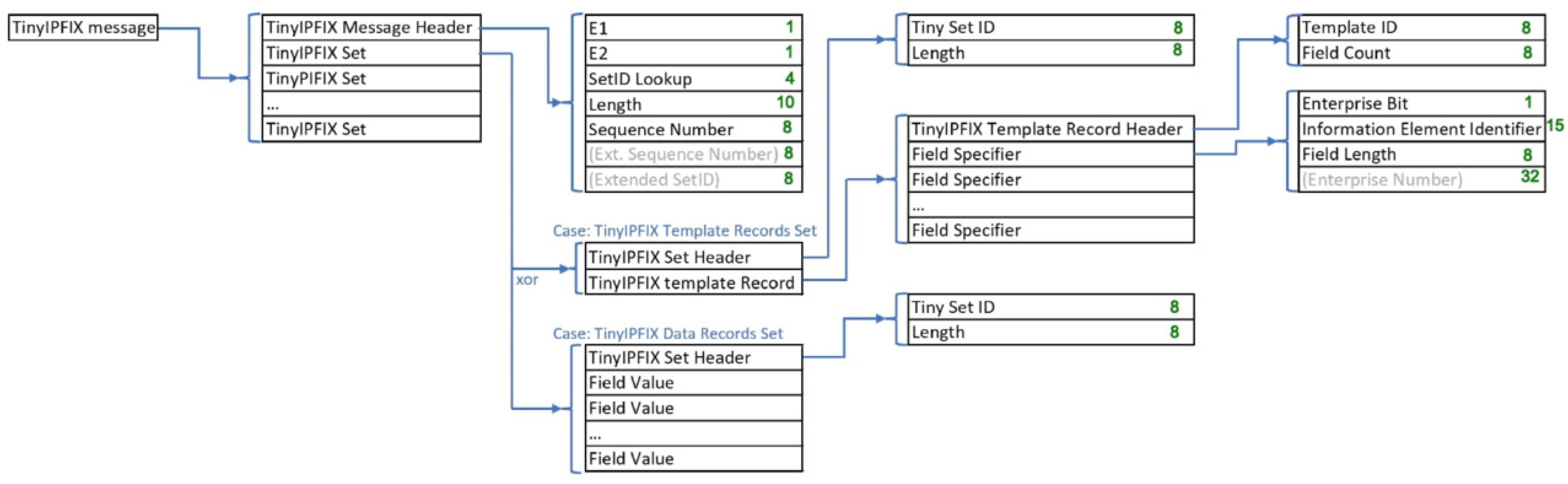
2.1.1. TinyIPFIX Messages
2.1.2. TinyIPFIX Message Header
2.1.3. TinyIPFIX Template Records Set
Set Header
Template Record
Field Specifier
2.1.4. TinyIPFIX Data Records Set
Set Header
Field Values
2.2. Communication Protocols for IoT Applications
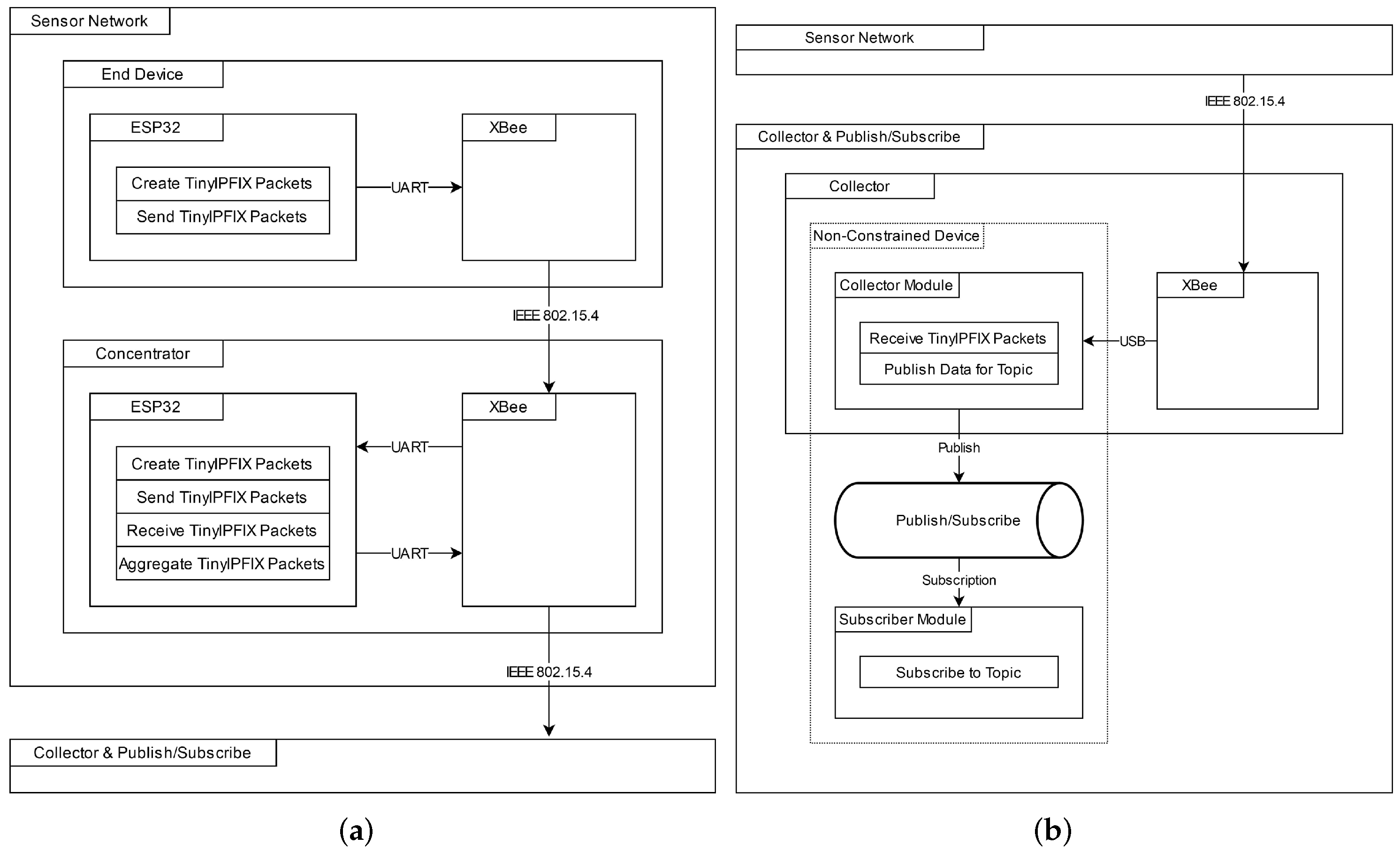
3. TinyIPFIX-based System Architecture
3.1. TinyIPFIX Sensor Network
3.1.1. TinyIPFIX Device (End Device)
3.1.2. TinyIPFIX Concentrator
3.1.3. TinyIPFIX Collector
3.2. Implementation
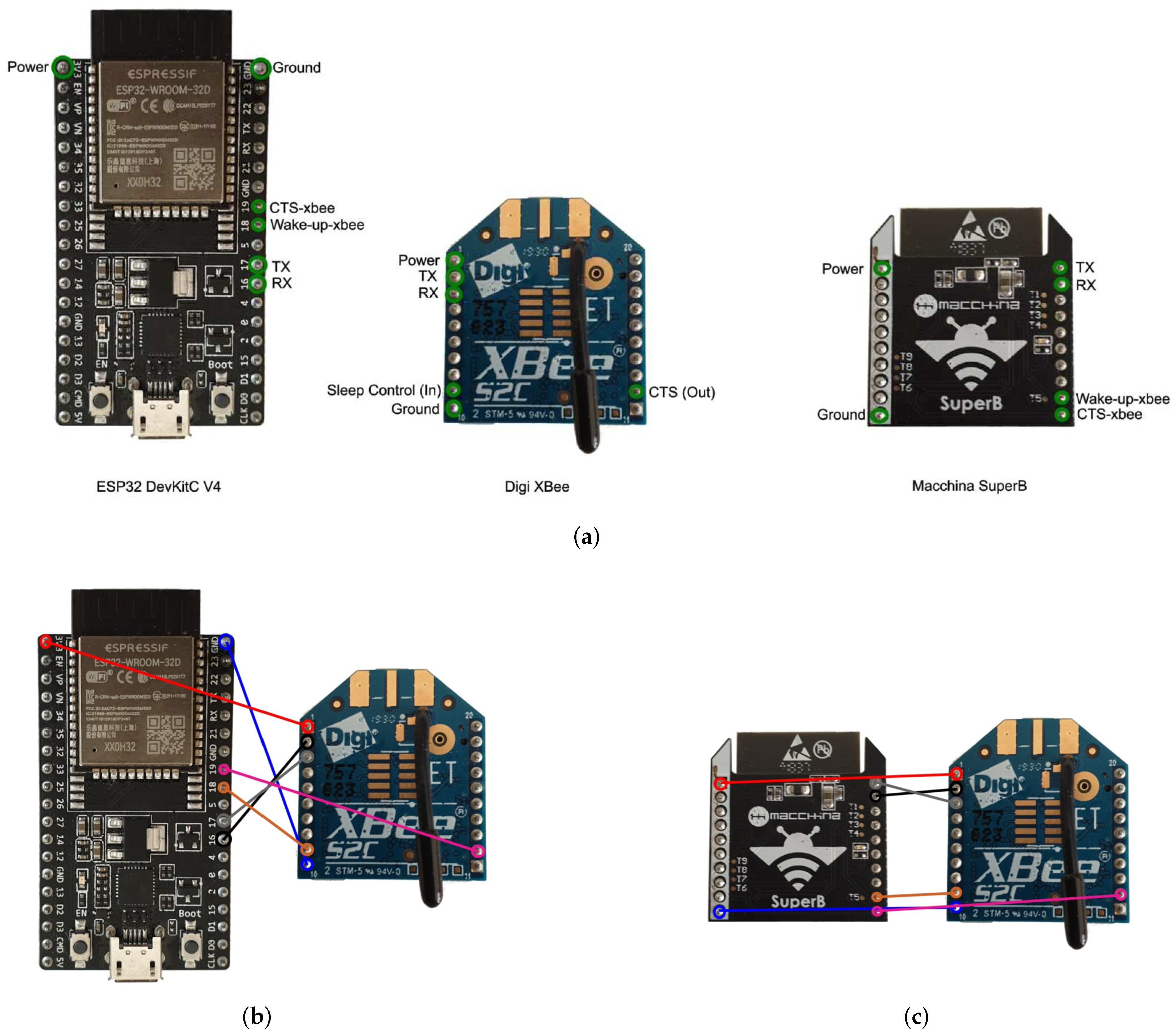
3.2.1. ESP32 Firmware Preparation
3.2.2. Connecting the ESP32-Based Device with XBee
3.2.3. Configuring XBee Devices
3.2.4. TinyIPFIX Protocol Implementation
TinyIPFIX Helper Functions Class
Tiny IPFIX Message Specific Classes
Device-Related Classes
Implementation of Collector and Application Related Classes
4. Evaluation
4.1. Network Configuration
4.2. Sensor Configuration
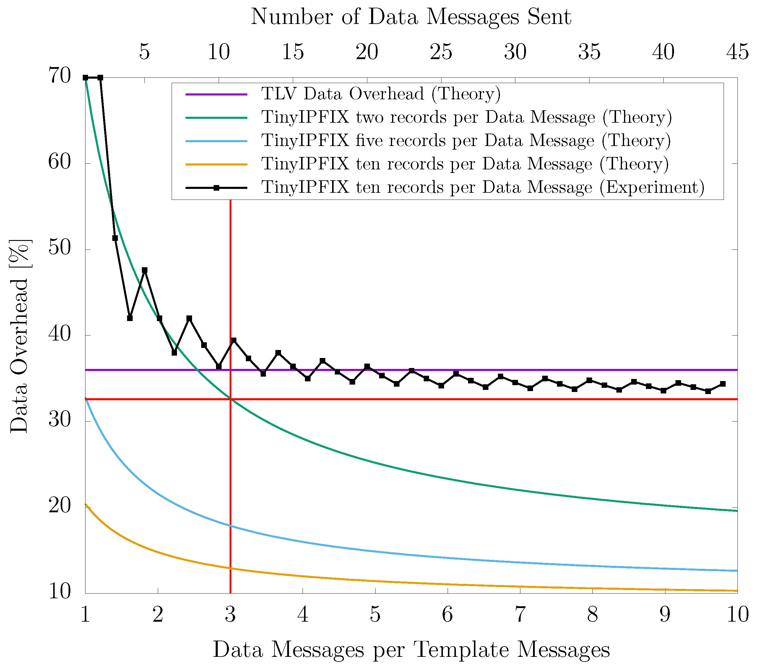
4.3. Data Overhead
4.4. Transmission Reliability
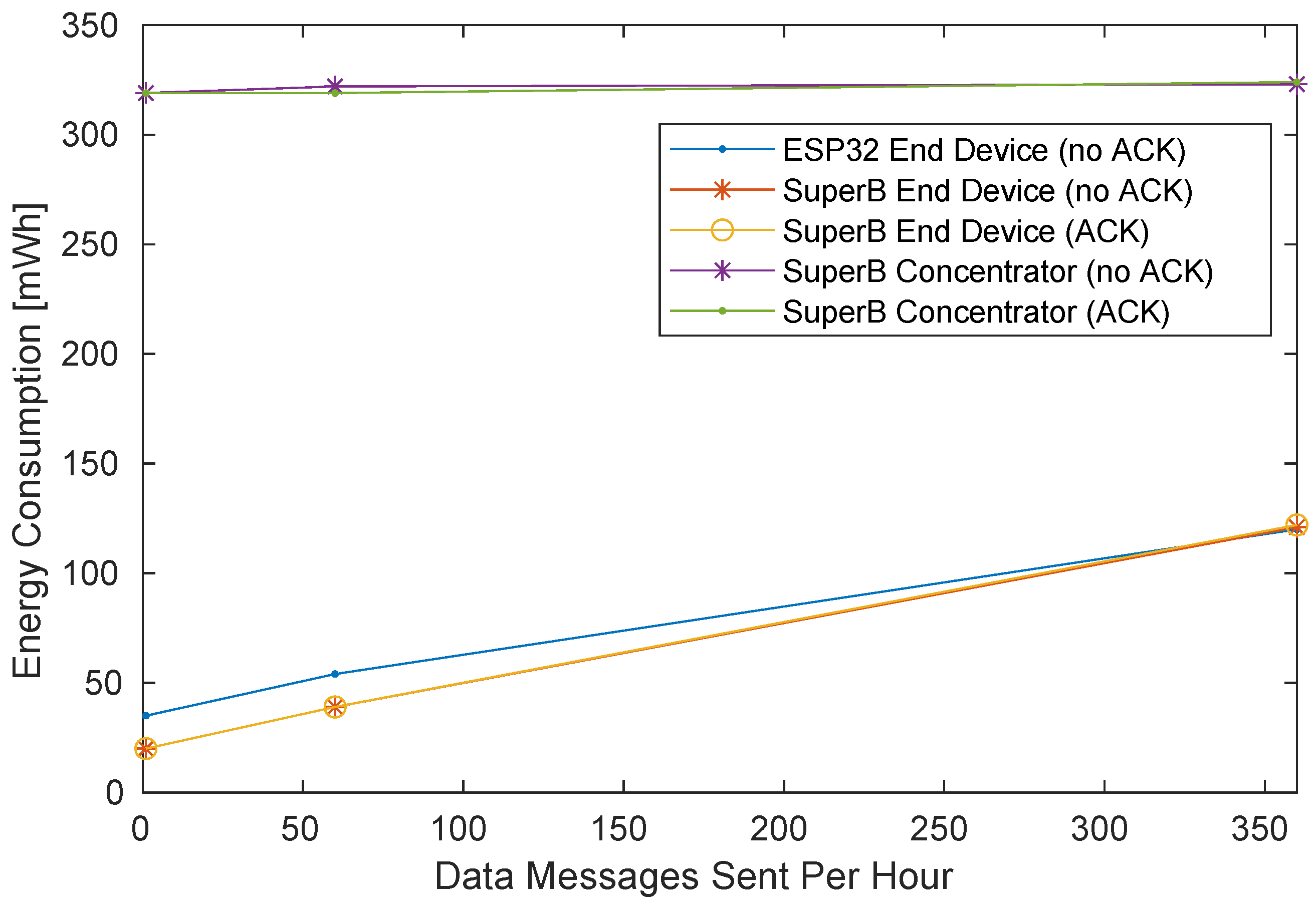
4.5. Energy Consumption
5. Summary, Conclusions, and Future Work
Author Contributions
Funding
Data Availability Statement
Conflicts of Interest
References
- Akyildiz, I.F.; Su, W.; Sankarasubramaniam, Y.; Cayirci, E. Wireless Sensor Networks: A Survey. Comput. Netw. 2002, 38, 393–422. [Google Scholar] [CrossRef] [Green Version]
- Espressif Systems. ESP32-WROOM-32D & ESP32-WROOM-32U Datasheet. V1.9. 2019. Available online: https://www.espressif.com/sites/default/files/documentation/esp32-wroom-32d_esp32-wroom-32u_datasheet_en.pdf (accessed on 30 May 2001).
- Maier, A.; Sharp, A.; Vagapov, Y. Comparative Analysis and Practical Implementation of the ESP32 Microcontroller Module for the Internet of Things. In Proceedings of the Internet Technologies and Applications (ITA), Wrexham, UK, 12–15 September 2017; pp. 143–148. [Google Scholar]
- MicroPython Homepage. Available online: https://micropython.org/ (accessed on 4 September 2020).
- Digi International. XBee/XBee-PRO S2C Zigbee RF Module User Guide. AG. 2020. Available online: https://www.digi.com/resources/documentation/digidocs/pdfs/90002002.pdf (accessed on 1 December 2021).
- IEEE Standard for Low-Rate Wireless Networks. IEEE Std 802.15.4-2020 (Revision of IEEE Std 802.15.4-2015). 2020. Available online: https://ieeexplore.ieee.org/document/9144691 (accessed on 1 December 2021).
- Schmitt, C.; Stiller, B.; Trammell, B. TinyIPFIX for Smart Meters in Constrained Networks. Available online: https://datatracker.ietf.org/doc/html/rfc8272 (accessed on 28 November 2018).
- Schmitt, C.; Kothmayr, T.; Ertl, B.; Hu, W.; Braun, L.; Carle, G. TinyIPFIX: An Efficient Application Protocol for Data Exchange in Cyber Physical Systems. Comput. Commun. 2016, 74, 63–76. [Google Scholar] [CrossRef]
- Stiller, B.; Schiller, E.; Schmitt, C. An Overview of Network Communication Technologies for IoT. In Handbook of Internet-of-Things; Ziegler, S., James, M., Eds.; Springer: Cham, Switzerland, 2020; Chapter 12. [Google Scholar]
- Claise, B.; Trammell, B. Information Model for IP Flow Information Export (IPFIX). Available online: https://datatracker.ietf.org/doc/html/rfc7012 (accessed on 1 December 2021).
- Claise, B.; Trammell, B.; Aitken, P. Specification of the IP Flow Information Export (IPFIX) Protocol for the Exchange of Flow Information. Available online: https://datatracker.ietf.org/doc/html/rfc7011 (accessed on 1 December 2021).
- Krishnamachari, L.; Estrin, D.; Wicker, S. The Impact of Data Aggregation in Wireless Sensor Networks. In Proceedings of the 22nd International Conference on Distributed Computing Systems Workshops, Vienna, Austria, 2–5 July 2002; pp. 575–578. [Google Scholar]
- Kothmayr, T. Data Collection in Wireless Sensor Networks for Autonomic Home Networking. Bachelor Thesis, Department of Computer Science, Technische University of Munich, Munich, Germany, 2010. [Google Scholar]
- Petija, R.; Glevaňák, M.; Kucan, M.; Fecil’ak, P.; Jakab, F. Experimental Implementation of TinyIPFIX Protocol for Arduino and Raspberry Pi Platform. In Proceedings of the 18th International Conference on Emerging eLearning Technologies and Applications (ICETA), Košice, Slovenia, 12–13 November 2020; pp. 519–524. [Google Scholar]
- Werner-Allen, G.; Swieskowski, P.; Welsh, M. MoteLab: A Wireless Sensor Network Testbed. In Proceedings of the Fourth International Symposium on Information Processing in Sensor Networks (IPSN’05), Los Angeles, CA, USA, 24–27 April 2005; pp. 483–488. [Google Scholar] [CrossRef]
- Polastre, J.; Szewczyk, R.; Culler, D. Telos: Enabling Ultra-Low Power Wireless Research. In Proceedings of the Fourth IEEE International Symposium on Information Processing in Sensor Networks (IPSN), Boise, ID, USA, 15 April 2005; pp. 364–369. [Google Scholar]
- Raspberry Pi Foundation Group. Raspberry Pi Products. Available online: https://www.raspberrypi.com/products (accessed on 2 October 2021).
- Louis, L. Working Principle of Arduino and Using It as a Tool for Study and Research. Int. J. Control. Autom. Commun. Syst. (IJCACS) 2016, 1, 21–29. [Google Scholar] [CrossRef]
- IANA IP Flow Information Export (IPFIX) Entities. Available online: https://www.iana.org/assignments/ipfix/ipfix.xhtml (accessed on 5 September 2020).
- Minaburo, A.; Pelov, A.; Toutain, L. LP-WAN Gap Analysis. Available online: https://tools.ietf.org/html/draft-minaburo-lp-wan-gap-analysis-00 (accessed on 28 November 2018).
- Raza, U.; Kulkarni, P.; Sooriyabandara, M. Low Power Wide Area Networks: An Overview. IEEE Commun. Surv. Tutor. 2017, 19, 855–873. [Google Scholar] [CrossRef] [Green Version]
- Sgier, L. TinyIPFIX Aggregation in Contiki. Available online: https://files.ifi.uzh.ch/CSG/staff/schmitt/Extern/Theses/Livio-Sgier-Internship.pdf (accessed on 31 May 2021).
- Ebi, C.; Schaltegger, F.; Rüst, A.; Blumensaat, F. Synchronous LoRa Mesh Network to Monitor Processes in Underground Infrastructure. IEEE Access 2019, 7, 57663–57677. [Google Scholar] [CrossRef]
- Schiller, E.; Huber, R.; Stiller, B. Python-Based TinyIPFIX in Wireless Sensor Networks. In Proceedings of the 46th IEEE Conference on Local Computer Networks (LCN 2021), Edmonton, AB, Canada, 4–7 October 2021; pp. 431–434. [Google Scholar] [CrossRef]
- ZeroMQ Messaging Patterns - Publish/Subscribe. Available online: https://learning-0mq-with-pyzmq.readthedocs.io/en/latest/pyzmq/patterns/pubsub.html (accessed on 10 October 2020).
- Huber, R. TinyIPFIX for ESP32, GitHub Repository. Available online: https://github.com/ramonhuber/TinyIPFIX-for-ESP32 (accessed on 1 December 2021).
- ESP32-DevKitC V4 Getting Started Guide. Available online: https://docs.espressif.com/projects/esp-idf/en/latest/esp32/hw-reference/esp32/get-started-devkitc.html (accessed on 7 November 2020).
- Macchina LLC. SuperB ESP32 Breakout—Overview. Available online: https://docs.macchina.cc/superb-docs/hardware (accessed on 20 September 2020).
- XCTU. Available online: https://www.digi.com/products/embedded-systems/digi-xbee/digi-xbee-tools/xctu (accessed on 7 November 2020).
- MySQL Data Type Storage Requirements. Available online: https://dev.mysql.com/doc/refman/5.6/en/storage-requirements.html#data-types-storage-reqs-date-time (accessed on 29 September 2020).
- DROK. UM25(C) Power Meter. Available online: https://www.droking.com/USB-C-Power-Meter-LCD-Display-USB-Meter-DC-4-24V-5A-UM25-Type-C-Voltage-and-Current-Tester (accessed on 1 December 2021).


| Technology | Communication Range | Throughput | MAC MTU (Byte) |
|---|---|---|---|
| LoRaWAN | 2–5 km urban, 15 km suburban | 0.3 to 50 kbps | 256 |
| SigFox | 10 km urban, 50 km suburban | 100 bps | Fixed 12 |
| IngenuRPMA | 20–65 km | up: 624 kbps down: 156 kbps | 64 |
| Weightless-N | 5 km urban 30 km suburban | 30 kbps to 100 kbps | max. 20 |
| LTE-M | 12 km | up: 1 Mbps down: 1 Mbps | 1500 |
| NB-IoT | 15 km | 200 kbps | 1600 |
| IEEE 802.15.4 | 10 m | 250 kbps | 127 |
| Device Name | MY | DL |
|---|---|---|
| Collector | C001 | E99E |
| End Device A.1 | E0A1 | A00A |
| End Device A.2 | E0A2 | A00A |
| End Device B.1 | E0B1 | A00B |
| End Device B.2 | E0B2 | A00B |
| Concentrator A | A00A | C001 |
| Concentrator B | A00B | C001 |
| Deep Sleep | Idle | Sending | Receiving | |
|---|---|---|---|---|
| ESP32 End Device | 35 mW | 190 mW | 344 mW | - |
| SuperB End Device | 20 mW | 158 mW | 308 mW | - |
| ESP32 Concentrator | - | 328 mW | 334 mW | 390 mW |
| ESP32 without XBee | 35 mW | 192 mW | - | - |
| XBee without ESP32 | - | 168 mW | - | 168 mW |
Publisher’s Note: MDPI stays neutral with regard to jurisdictional claims in published maps and institutional affiliations. |
© 2022 by the authors. Licensee MDPI, Basel, Switzerland. This article is an open access article distributed under the terms and conditions of the Creative Commons Attribution (CC BY) license (https://creativecommons.org/licenses/by/4.0/).
Share and Cite
Schiller, E.; Huber, R.; Stiller, B. Python-Based TinyIPFIX in Wireless Sensor Networks. Electronics 2022, 11, 472. https://doi.org/10.3390/electronics11030472
Schiller E, Huber R, Stiller B. Python-Based TinyIPFIX in Wireless Sensor Networks. Electronics. 2022; 11(3):472. https://doi.org/10.3390/electronics11030472
Chicago/Turabian StyleSchiller, Eryk, Ramon Huber, and Burkhard Stiller. 2022. "Python-Based TinyIPFIX in Wireless Sensor Networks" Electronics 11, no. 3: 472. https://doi.org/10.3390/electronics11030472
APA StyleSchiller, E., Huber, R., & Stiller, B. (2022). Python-Based TinyIPFIX in Wireless Sensor Networks. Electronics, 11(3), 472. https://doi.org/10.3390/electronics11030472