Abstract
In this paper, a multi-strategy routing protocol, reactive-greedy-face (RGF), is proposed based on the advantages of reactive forwarding, greedy forwarding, and projected face forwarding strategies. This protocol improves and unites the strategies through a reasonable selection and switching mechanism to make up for the deficiencies of the existing three-dimensional routing protocols in the flight self-assembly network and improve the rapid recovery of packet forwarding after topology changes. The simulation validation shows that this routing protocol can be used to recover packets after a topology change. Simulation verification indicates that the routing protocol significantly improves the packet delivery rate and the average end-to-end delay performance, and can better adapt to the flight self-assembly network’s three-dimensional high-dynamic and low-density characteristics.
1. Introduction
Recently, the unmanned aerial system (UAS) has set off a development upsurge in the world; it has a wide range of applications in photography, entertainment, emergency rescue, counter-terrorism, stability maintenance, and agricultural remote sensing [1,2,3,4]. With the increasing demand for UAVs in the civil and military fields, the UAS uses many multi-UAV cooperation methods and has furthered cluster, information, and intellectual development. As with a single UAV system, multi-UAV systems can also allow UAVs to communicate by connecting with a ground control station (GCS) or satellite [5]. However, the hardware equipment needed by UAVs to communicate through satellites is expensive, and there are limits to the range of communication through ground control stations. To solve the problem of communication between multiple UAVs, an effective solution is to introduce the technology of ad hoc networks. The flying ad hoc network (FANET) [6] proposed by İlkerBekmezci et al. is a fast and efficient solution for realizing the networking of multiple UAVs by using ad hoc technology. In the FANET, some UAVs can communicate with a ground control station, and the other part can communicate with a satellite. All UAVs eventually form a self-organizing network. This way, UAVs can communicate with each other and with ground control stations. The FANET is a three-dimensional high-dynamic network. In existing mobile ad hoc networks and wireless sensor networks (WSNs), the research on two-dimensional geographic location routing protocols has been quite mature. Therefore, many of the three-dimensional geographic location routing protocols in the FANET are the expansion of corresponding two-dimensional protocols in a three-dimensional space, but the effect of expansion is limited. For example, greedy routing in a three-dimensional topology is more likely to fall into local minima than greedy routing in a two-dimensional topology, that is, to encounter a routing hole, which leads to greedy routing failure. Durocher et al. proved that there is no deterministic local memoryless routing algorithm in a three-dimensional space that can ensure the delivery of data packets [7], which also means that the uncertain recovery routing algorithm can ensure that data packets jump out of the routing hole. Therefore, the design of an efficient three-dimensional geographic location routing protocol is still facing great challenges.
Many researchers have studied the operation of traditional ad hoc network routing protocols in the FANET and have achieved some results, but they still need to improve and develop new routing protocols according to the characteristics and requirements of the FANET. In [8], the traditional ad hoc on-demand distance vector routing (AODV) protocol can be improved by adding the location and heading information of the source node as well as a minimum expected connection time (minCT) and maximum risk value to the RREQ packet as a joint measure to select the best route. The reactive green reactive (RGR) protocol proposed in [9] combines a reactive routing mechanism with greedy geographic forwarding. Once the reactive path is interrupted, the existing packets will be saved by greedy geographic forwarding during the re-routing. The RGR protocol effectively reduces the delay while maintaining the overhead of the conventional routing level. In the literature [10,11,12], the AntHocNet protocol, based on the ant colony algorithm, and the BeeAdHoc protocol, based on the bee colony algorithm, were analyzed. Simulation results showed that the heuristic algorithm based on swarm intelligence is more suitable for the flight ad hoc network characterized by high-speed data transmission and high node mobility. The authors of [13] proposed a predictive routing algorithm for the flight ad hoc network based on the clustering structure. The algorithm uses the improved Dijkstra algorithm to calculate the minimum end-to-end delay path, which avoids link loss in the transmission process. In [14], an adaptive beacon scheme called ABPP (adaptive beacon and position prediction) was proposed for the geographic location routing protocol. ABPP uses historical location information to predict the future location of UAVs through a weighted linear regression model, which effectively reduces the channel overhead. In [15], a greedy location-assisted routing scheme based on fountain code was proposed, which was called FGPA (fountain code-based green position assisted routing). FGPA takes the relative motion trend between two UAV nodes as a new measure. The authors of [16] proposed an adaptive forwarding protocol (AFP) in a 3D space. AFP can reduce unnecessary replay and conflict between neighbor nodes based on forwarding probability and region standards. In [17], the hybrid routing protocol HSRP (hierarchical space routing protocol) was proposed based on the ZRP protocol. The HSRP protocol uses the flow rate mechanism to select table-driven or on-demand routing protocols. In [18], aiming at the topological structure in the dynamic change of an ad hoc network, the topological network structure of the recording platform was designed by using the random constant speed moving model (RCS), which made the simulation scene closer to the dynamic performance of the high-dynamic mobile node. In [19], a novel routing protocol inspired by the cuckoo search algorithm was proposed. The latest meta-heuristic cuckoo search algorithm (CSA) was used to improve the AODV routing protocol and identify the shortest path between two nodes. The authors of [20] proposed a FANET routing protocol, PSO-GLFR, based on greedy forwarding and limited flooding. Particle swarm optimization was used to solve the problem of greedy forwarding suboptimal selection and realize low delay and low power routing support. In [21], a geographic location-based routing protocol was proposed to reduce routing overhead using neighbor geographic location information. In [22], a multi-data rate mobility aware (MDRMA) protocol was proposed. The MDRMA protocol is the primary extension of a self-organizing distance vector in two-way mobile sensing with adaptive HELLO message protocol, which can quickly generate stable routes and reduce link failures. In [23], an adaptive greeting interval scheme (EE-HELLO) was proposed, reducing energy consumption under the same packet transmission rate. In [24], based on dynamic source routing (DSR), a continuous Hopfield neural network was used to optimize routing to adapt to the FANET network. The optimized DSR protocol improved the key performance of routing. In [25], an adaptive hybrid communication protocol was proposed, including position prediction-based directional MAC (PPMAC) and a self-learning method. The protocol provides a highly autonomous communication solution.
Most three-dimensional geographic location routing protocols use two working modes simultaneously: the greedy mode (greedy routing) and the recovery mode (recovery routing, also known as bypass mode or bypass routing). The greedy mode ensures packets are forwarded in advance, while the recovery mode is mainly used to make packets jump out of routing holes or loops when the greedy mode encounters a local minimum or routing loops. The three-dimensional geographic location routing protocol will generally follow the following basic principles: Each node knows its 3D location information. In some cases, nodes can use a virtual location instead of an actual location to simplify the configuration. Currently, the sending node knows the location information of the surrounding neighbor node and the destination node. Each node needs to exchange location information with the neighbor node, which can be achieved by periodically sending beacon messages. The current routing decision of the sending node is based on local information and is fully distributed. Generally, the current sending node selects the next-hop forwarding node according to its own location, the neighbor node’s location, and the destination node’s location. The current sending node uses the greedy mode to decide on the next-hop forwarding node. The common way this is achieved is through greedy geographic forwarding (GGF) [26]. For the switch of the recovery mode, when the current sending node encounters a local minimum or routing loop, the greedy mode will not continue to work. At this time, the protocol needs to switch to the recovery mode to forward packets until it jumps out of the routing hole or loop and then switches back to greedy mode. According to the above principles, the three-dimensional geographical location routing protocol can be designed reasonably, which can efficiently complete the communication task of the flight ad hoc network. However, the structure of the 3D dynamic network is complex. Making 3D geographic location routing work efficiently with a reasonable switch routing strategy has become a hot and arduous task in the FANET.
However, previous FANET routing protocols have focused on selecting the best path through joint metrics, although they use greedy and recovery modes. Although some researchers have considered network topology dynamics, most researchers have determined routing paths with the idea of studying the UAV location or trajectory prediction, for example. With the rapid changes in the routing environment brought about by the highly dynamic motion of UAVs, few researchers have conducted studies. At this stage, there is a lack of routing protocols for fast strain in different topological situations caused by highly dynamic flying UAVs. We have built on previous research to design routing switching strategies to adapt to highly dynamic changing UAV networks based on different network scenarios brought about by highly dynamic UAV flights. The previous study also improved the routing strategy to make it more suitable for the FANET.
According to the characteristics of a three-dimensional network, when routing protocols encounter different network environments, routing forwarding can be effectively completed by selecting different routing strategies. Compared with the previous scheme, the proposed three-dimensional geographic location routing protocol, RGF, can complete the communication task of the FANET more effectively. The overall idea of the protocol is to provide a low overhead and scalable location services through the routing discovery process of the HELLO packet active flooding strategy and reactive fisheye technology, and to effectively improve the location acquisition ability of the 3D network. The reactive path in the 3D network is easily interrupted. At this time, the improved greedy forwarding can immediately transmit data packets and improve the link duration of the 3D network. However, greedy forwarding easily falls into local minima and forms routing holes in three-dimensional networks. Multi-path projection face forwarding can help packets jump out of routing holes. Projection face can easily generate path expansions, which can avoid potential path expansions by switching to reactive mechanism forwarding. The simulation results show that RGF can effectively improve the routing and forwarding capability of the FANET.
The main contributions of this paper are summarized as follows:
- We propose a multi-strategy routing RGF protocol to solve the topological high-dynamic problem of the FANET by reasonably selecting and switching different forwarding policies.
- We propose a hybrid location service strategy that can achieve the low overhead, scalable location services required by the RGF protocol.
- We improve the traditional reactive path-building mechanism and greedy geographic forwarding mechanism to make the selected path or next-hop node more reasonable.
- We propose a multi-path projected face forwarding policy and directionally adaptive forwarding rules to avoid routing loops, reduce path sprawl, and improve the efficiency of jumping out of routing holes.
The research scheme is shown in Figure 1. The rest of this paper is arranged as follows: Section 2 introduces the relevant research content, Section 3 is the location service design of the routing protocol, Section 4 is the forwarding strategy selection and handover method, Section 5 is the specific forwarding strategy design, and Section 6 is the simulation analysis of the experiment.
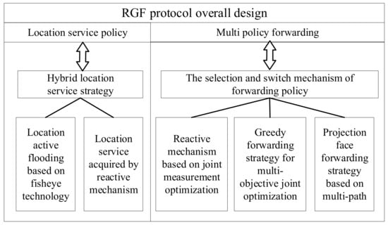
Figure 1.
RGF protocol overall design.
2. Hybrid Location Service Strategy Design
Although the flooding-based method is practical in some traditional location-based service methods, it needs a high consumption of network resources. It is difficult to apply the set-based method to high-dynamic networks because the nodes in the update set and search set will constantly change, so it is necessary to constantly adjust the node set at the intersection. However, the method based on attribution generally needs some fixed nodes or infrastructure as location servers, which is not conducive to the deployment and expansion of the network.
Therefore, a hybrid location service strategy was used in the RGF protocol, which combined proactive and reactive mechanisms. In a certain range, the location information and motion information between nodes are exchanged in the way of active flooding. Outside the range, the target node’s location information and motion information are obtained on demand by building a reactive path, which effectively controls the cost of flooding and ensures the scalability of this location-based service scheme.
In the proactive location service, an active flooding strategy based on fisheye technology was adopted, as shown in Figure 2.
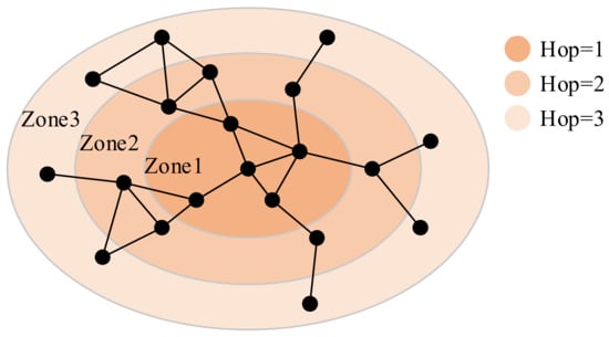
Figure 2.
Scope of fisheye.
Each node needs periodic flooding HELLO messages, and the remaining forwarding times field controls the size of the flooding area. Each time the intermediate node forwards a HELLO message, it is necessary to reduce the value of the remaining forwarding times by 1. When the value of the remaining forwarding times is 0, the HELLO message will not be forwarded. Therefore, the coverage area of HELLO messages can be controlled by setting the initial number of the remaining forwarding times, reducing the cost and ensuring the scalability of the proactive location service. The average update frequency in different areas will be different. The closer the node gets, the higher the average update frequency, and the more accurately the location and motion information can be maintained.
In addition, considering the high mobility of UAVs, the faster the UAV moves, the more frequently the position changes. Therefore, to obtain the latest location information in time, the update cycle of the HELLO message should be short. The node in AODV is usually set to route outage when it does not receive HELLO messages from the next-hop node twice in a row. The HELLO message interval is usually set to 1 s. Therefore, if the next-hop node has moved out of the communication range of the current node, the current node will only know after 2 s, so the packets transmitted during this temporary blind period will be lost. Therefore, the update period of the HELLO message should be less than or equal to 0.5 s. Here, Equation (1) is used to adjust the HELLO message’s update cycle dynamically.
In the formula, represents the current update cycle of the HELLO message, is the minimum update cycle of the HELLO message, and represents the UAV’s motion rate, , .
When the destination node is out of the fisheye range, it will not be able to obtain the HELLO message of the destination node regularly, and the source node will not be able to obtain the location information and motion information of the destination node. Therefore, we need to obtain the information of the destination node through the reactive location service. The reactive location service process is shown in Figure 3, which is realized through the route discovery process of the reactive mechanism.
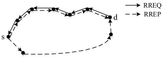
Figure 3.
Reactive location service.
In reactive location service, the source node and the destination node use the reactive mechanism’s RREQ message and RREP message for route discovery to build a reactive path. Among them, the RREQ message encapsulates the location information, motion information, time stamp, and effective time of the source node, and the RREP message encapsulates the location information, motion information, time stamp, and effective time of the destination node. Therefore, through the interaction of the two messages, the source node will obtain the location and motion information of the destination node. The reactive path constructed will also be used for the subsequent packet forwarding of the reactive mechanism.
3. Forwarding Policy Selection and Handover Design
In the RGF protocol, each packet contains a packet header to control the packet forwarding policy. The main fields of the packet header are shown in Figure 4. The source node needs to determine the initial forwarding policy for these packets, and the intermediate node must also change the forwarding policy according to the situation.
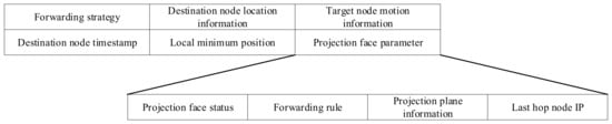
Figure 4.
RGF data packet header format.
3.1. Forwarding Policy Selection
In the RGF protocol, the source node must select and set the initial forwarding policy of the packet, as shown in Figure 5.
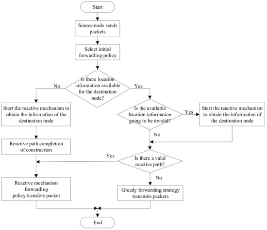
Figure 5.
The process by which the source node selects the forwarding strategy.
Suppose the source node does not have the effective location information of the destination node. In that case, it needs to start the reactive mechanism of the hybrid location service to build a reactive path and obtain the location information of the destination node, and then use the path to execute the reactive mechanism to forward the policy to transmit the data packet. If the source node has valid location information for the destination node, and there is also a reactive path available, the path will also be used first to transmit packets. Suppose the source node has valid location information for the destination node, but there is no available transmission path. In that case, the greedy forwarding strategy will be used to transmit the packets directly. In addition, if the source node finds that the location information of the destination node is about to be invalid, it actively obtains the location and motion information of the destination node through the reactive location service. At the same time, the current packet can still encapsulate the effective information of the destination node for transmission, thus avoiding the waiting delay caused by the need to retrieve the information of the destination node.
The process of selecting the forwarding policy for intermediate nodes is shown in Figure 6.
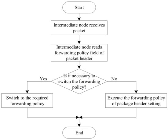
Figure 6.
The process by which the intermediate node selects the forwarding strategy.
When an intermediate node forwards a packet, it first selects the forwarding policy of the packet according to the forwarding policy field in the packet header. Only when the handover conditions are met can the intermediate node change the forwarding policy of the packet. Otherwise, even if the intermediate node has a reactive path to the destination node, if the packet is currently greedy forwarding and the intermediate node is not the minimum local node, the intermediate node also needs to forward the packet with a greedy forwarding strategy.
3.2. Forwarding Policy Switching
When the current packet forwarding strategy is the reactive mechanism, the intermediate node must check whether the next-hop node on the reactive path is still in the communication range. If it is, the intermediate node will continue to perform reactive mechanism forwarding and forward the packet to the corresponding next-hop node. Otherwise, it will switch to greedy forwarding, as shown in Figure 7.
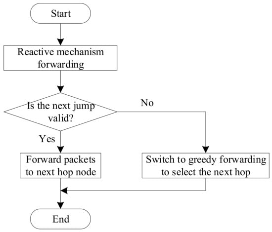
Figure 7.
Switching conditions under the reactive mechanism.
When the current packet forwarding strategy is greedy forwarding, the intermediate node must determine whether it is a minimum local node. If it is not, it will continue to use greedy forwarding. If it is, it will check whether there is a reactive path available. If there is, it will switch to reactive mechanism forwarding. Otherwise, it will use projection face forwarding, as shown in Figure 8.
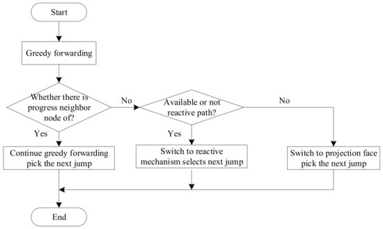
Figure 8.
Switching conditions under greedy forwarding.
When the current packet forwarding strategy is to project face, the intermediate node first needs to determine whether it has jumped out of the routing hole. If so, the intermediate node will switch back to greedy forwarding. If not, then it will determine whether there is a reactive path available. If so, it will switch to reactive mechanism forwarding. If not, it will continue to perform projected face forwarding, as shown in Figure 9.
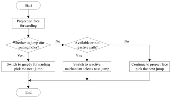
Figure 9.
Switching conditions under the projection face.
4. Forwarding Strategy Design
4.1. Reactive Mechanism Design Based on Joint Measurement Optimization
Due to the highly dynamic nature of the FANET, the network topology can change at any time. Therefore, to ensure the stability of the constructed reactive path, the RGF protocol needs to add a minimum link expiration time word segment in the RREQ message and RREP message of the reactive mechanism used. If node and node are in communication range of each other, the three-dimensional position and speed vectors of the nodes are and , respectively. The three-dimensional position and velocity vectors of node are and , respectively. Then, the link expiration time (LET) between node and node is calculated according to Equations (2) and (3).
When forwarding RREQ or RREP, each intermediate node needs to calculate the link expiration time with the previous hop node and then compare it with the value in the minimum link expiration time field. If it is less than the value recorded in this field, it will be replaced with a new value. Therefore, the “minimum link expiration time” field in RREQ or RREP will record the minimum value of all link expiration times on the path that the message passes, that is, the expiration time of the path, where RREQ records the expiration time on the reverse path to the source node, and RREP records the expiration time on the forward path to the destination node.
The destination node must start a short timer after receiving the first RREQ. According to the received RREQ during the timing period, a joint metric is calculated for each path according to Equation (4). After the timer expires, the path with the largest joint metric value is activated by RREP.
In Equation (4), represents the joint metric, represents the minimum link expiration time, and represents the number of path hops. The path selected according to Equation (4) will have a certain stability, which can avoid the handoff of the forwarding strategy as much as possible, and can consider the number of hops, which can ensure a lower delay.
After receiving the RREQ or RREP, other intermediate nodes also need to calculate the joint metric value for the newly discovered forward or reverse path according to Equation (4). Suppose there is active forward or reverse routing information in the routing table. In that case, intermediate nodes also need to calculate the current joint metric value on the old path as recorded in Equation (5).
In the formula, is the latest joint measure of the old path, is the joint measure recorded in the routing table when the old path is constructed, is the current time, is the time stamp recorded in the routing table, and K is the number of hops recorded in the routing table.
When one of the following conditions is met, the intermediate node needs to update the routing table:
a. The new serial number is greater than the destination node’s serial number stored in the routing table;
b. The two serial numbers are equal, but the joint measure of the new path is greater than the current joint measure of the old path;
c. The new serial number is an unknown serial number.
The design algorithm of the reaction mechanism is as follows:
| Algorithm 1: The path construction process of the reactive mechanism of the RGF protocol. |
|
| Algorithm 2: RGF protocol reactive mechanism forwarding packet flow |
|
4.2. Greedy Forwarding Strategy Design Based on Multi-Objective Joint Optimization
RGF encapsulates the destination node’s location and motion information in the packet header, so it can switch to a greedy forwarding strategy when the reactive path is interrupted. The greedy forwarding of the RGF protocol adopts the greedy geographical forwarding method, and the forwarding node needs to forward the packets to the neighbor node closer to the destination node than itself. In order to ensure the stability of packet transmission, when the RGF protocol performs greedy forwarding, the forwarding node also needs to calculate the corresponding link expiration time for each neighbor node closer to the destination node according to Equations (2) and (3), to select the next hop with a stable link.
In addition, if the sending queue of the next-hop node is long, the packet will be sent to the node, which will obviously increase its load. At the same time, if the remaining energy of the next-hop node is low, the packets will be forwarded to the node, which will cause the node to die faster, and the packets that the node has not yet sent will also be lost. Therefore, considering load balancing and energy saving, each node’s HELLO message also encapsulates the sending queue length and remaining energy of the node. The forwarding node will finally calculate a transmission cost for each neighbor node closer to the destination node according to Equation (6) and select the node with the lowest cost as the next hop.
In the formula, represents the transmission cost, represents the distance from the neighbor node to the destination node, represents the distance from the current node to the destination node, represents the normalized transmission queue length of the neighbor node, represents the link expiration time between the current node and the neighbor node, represents the remaining energy of the neighbor node, and ,,, is the corresponding weight and meets the requirements of and .
According to Equation (6), there will be a relatively stable link between the next-hop node selected by greedy forwarding and the current node. The node’s load is low, and the remaining energy is also relatively sufficient, so it can ensure the reliability of packet transmission, reduce the delay of intermediate forwarding, and eliminate the nodes with low power consumption to achieve a multi-objective joint optimization. The specific algorithm is as follows:
| Algorithm 3: RGF protocol greedy forwarding packet process |
|
4.3. Design of Projection Face Forwarding Strategy Based on Multi-Path
When greedy forwarding encounters a local minimum, and no available reactive path needs to be re-routed, the RGF protocol will use projection face as a temporary forwarding strategy to transmit the received packets during reactive path establishment. Because projection face forwarding only needs to use the information within the local scope, it will not bring additional overhead, and it is relatively flat or has node density in the network. When it is high, projection face forwarding can show a better performance. However, in the FANET, because of the strong mobility of nodes, the rapid change in topology, and the low density of nodes, the direct use of traditional projection face forwarding based on a single path will still bring higher path expansion and increase the delay of packet delivery. Therefore, the RGF protocol improves the traditional projection face forwarding in three aspects to improve its performance.
4.3.1. Selection of Projection Nodes
In the projection face forwarding of the RGF protocol, only the 3DRNG or 3DGG neighbor node of the current forwarding node is used for projection. That is to say, the network topology is simplified by constructing a 3DRNG graph or 3DGG graph. Then, the one-hop neighbor node after topology simplification is projected vertically onto the projection plane so that a local clear projection face can be obtained after projection, and there is no cross. Since the next-hop forwarding node must be selected from the 3DRNG or 3DGG neighbor nodes, the forwarding rules can still be executed normally.
4.3.2. Construction and Forwarding of Multi-Projection Plane
To improve the projection face forwarding out of the routing hole, the projection face forwarding of the RGF protocol adopts a multi-path strategy: constructing multiple projection planes simultaneously and transmitting a corresponding copy of the data packet on different projection planes. As shown in Figure 10, the minimum local node needs to encapsulate its current location in the local minimum location field of the packet header and then broadcast the packet to all its 3DRNG or 3DGG neighbor nodes. These nodes construct the corresponding projection plane according to their position, the position of the destination node, and the position of the local minimum value recorded in the packet header, save the information of the plane in the projection face parameter field of the packet header, and then forward the received copy of the packet on the projection plane.
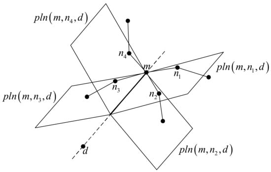
Figure 10.
Construction of multi-projection plane.
Because of the projection of multiple planes, and the same group of nodes in different projection planes, the next-hop node selected may be different, so the occurrence of the loop can be avoided to some extent. Because multiple copies of packets are transmitted at the same time, the probability of packets jumping out of the routing hole can be increased, and the path expansion can be reduced.
4.3.3. Direction-Adaptive Forwarding Rules
The projection face of the RGF protocol adopts a rule called direction-adaptive forwarding (DAF). The DAF rule enables the node in Figure 11 to rotate the link with the node in a clockwise direction so that the forwarding node of the next hop is , while the node selection remains unchanged.
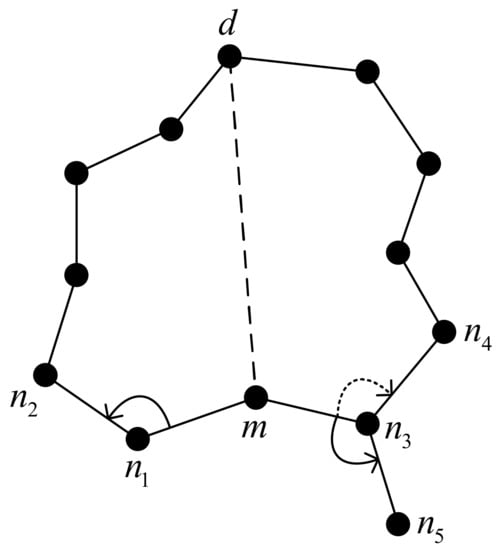
Figure 11.
Wrong search area.
The DAF rule combines the right-hand rule and left-hand rule. The left-hand rule is shown in Figure 12. The current node finds the next-hop node in the plan by rotating the link with the previous hop node clockwise around itself, so it can generally traverse the interior of a face anticlockwise. X, Y and Z represent different nodes.
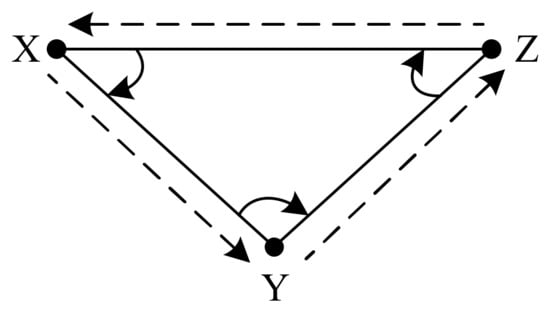
Figure 12.
Left-hand rule.
The DAF rule is composed of two sub-rules. Sub-rule 1 determines whether the initial forwarding rule is a right-hand rule or a left-hand rule, while sub-rule 2 determines when it is necessary to switch the forwarding rule from the right-hand rule/left-hand rule to the left-hand rule/right-hand rule. Suppose on the projection plane, the location of the local minimum value recorded in the packet header is , the projection of the destination node is , the projection of a 3DRNG or 3DGG neighbor node of the local minimum value node is , the connection between point and node is , the connection between point and node is , a node in the forwarding process is , the last-hop node of the node is , and the connection between point and node is . Then, the two sub-rules of the DAF rule are described as follows:
Sub-rule 1: if the connecting line rotates counterclockwise around the touchpoint (the angle should be less than 180°) to the connecting line , then the node and its subsequent nodes will traverse the face with the right-hand rule; if the connecting line rotates clockwise around the touchpoint (the angle should be less than 180°) to the connecting line , then the node and its subsequent nodes will traverse the face with the left-hand rule.
Sub-rule 2: if node forwards the packets to node through the right-hand rule/left-hand rule, and node detects that there is a cross between line and line , then node and the nodes after it need to switch to the left-hand rule/right-hand rule.
Figure 13 shows an example of the DAF rule, in which node and node decide the initial forwarding rule according to sub-rule 1, and node switches the right-hand rule to the left-hand rule according to sub-rule 2 and implements face switching.
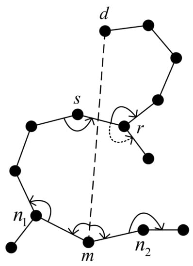
Figure 13.
An example of DAF rules.
DAF rules expand the search area of projection face forwarding, reduce the possibility of routing loops and repeated searches, improve the probability of packets jumping out of routing holes, and also, to a certain extent, inhibit path expansion and reduce the delivery delay of packets. The specific algorithm is as follows:
| Algorithm 4: RGF initialization process of projection face forwarding protocol |
|
| Algorithm 5: The projection face of the RGF protocol forwards packets |
|
5. Experimental Results and Discussion
In this experiment, OMNeT++ software was used to build the scene. UAV nodes were randomly distributed, and different random topologies were generated by setting different random seeds. The basic parameter settings are shown in Table 1.

Table 1.
Simulation parameters.
In the existing research on the FANET, the reactive routing protocol AODV, based on the network topology and the greedy geographic forwarding routing protocol (greedy) based on the whole network flood model location service, is widely used. However, the service performance of the above protocols is limited in the three-dimensional high-dynamic network topology environment. The existing common improvements include the combination of intelligent optimization algorithms to improve the routing protocol, such as the AntHocNet [13] routing protocol, and some combined routing protocols, such as the combination of the optimization and greedy PSO-GLFR [21] routing protocol. AntHocNet and GLFR represent the two improved algorithms in the comparison test diagram. This experiment verified the advantages of the proposed RGF routing protocol compared with the traditional routing protocol and the improved routing protocol in the above environment through the simulation of the flight ad hoc network scene by the above parameters. The experiment used three commonly used indicators to analyze the protocol’s performance, including the delivery rate, the average delay, and the routing cost, and verified the superiority of each indicator proposed in this paper under different mobile speeds and different nodes.
Figure 14, Figure 15 and Figure 16 show the comparison experiments of each index of the five protocols under different node-mobility speeds.
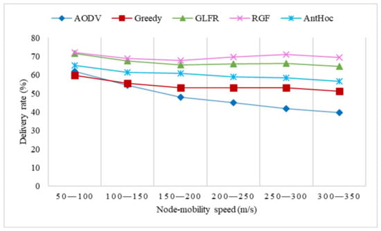
Figure 14.
The effect of velocity on the delivery rate.
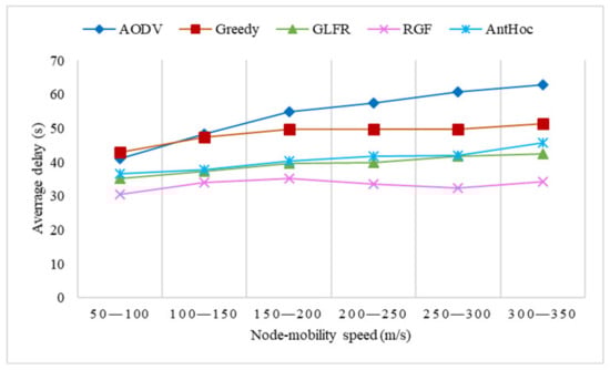
Figure 15.
The effect of velocity on average delay.
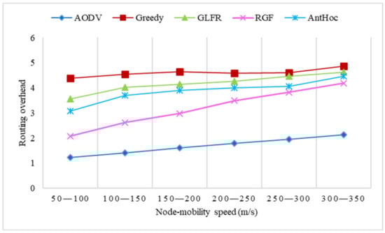
Figure 16.
The effect of velocity on routing overhead.
From Figure 14, it can be seen that the delivery rate of all protocols was not high, mainly due to the small number of nodes and the sparsity of the network. As the node movement speed increased, the delivery rate of AODV underwent a significant decrease, which was due to the lack of location awareness in AODV. The faster the nodes move, the more serious the packet loss is. In contrast, greedy, RGF, GLFR, and AntHocNet encapsulated node movement information in HELLO messages so that the current position of the next-hop node could be calculated before transmitting packets. The low delivery rate of greedy was due to the fact that greedy geographic forwarding is more likely to encounter local minima in a 3D scenario when the node can only wait for the routing hole to eliminate itself before continuing to transmit packets. In contrast, RGF can use the projection face forwarding strategy to continue transmitting packets when greedy forwarding encounters a local minimum, and the minimum local node will also start the reactive path construction at the same time and later transmit packets to jump out of the routing hole through the reactive mechanism forwarding strategy. From the figure, we can see that the delivery rate was the lowest when the nodes moved at 150–200 m/s, which was because the packet delivery efficiency was high when the nodes moved at a slower speed. However, after the node movement speed reached a certain level, the node movement speed was not the primary influence in ensuring the delivery rate. Due to faster path changes, routing holes became the main effect. At 150–300 m/s, as the movement speed became faster, path changes helped to break the routing hole. However, after more than 300 m/s, the node movement speed gradually increased in its impact on packet delivery because the location-aware efficiency of the routing protocols gradually decreased after the node speed increased to a certain level, which affected the accurate construction of paths.
Figure 15 demonstrates that with an increase in the node movement speed, the average delay of AODV experienced a significant increase, mainly because the increase in the node movement speed would have led to more frequent changes in the network topology, and route interruptions would have been more likely to occur. Therefore, nodes would need to continuously send RREQs and RREPs to establish new transmission paths, which would cause a larger delay; at the same time, the delivery rate was the worst. GLFR and AntHocNet were not sensitive to topology changes, and the average delay increased more gently, while when the forwarding encountered a local minimum, the node could only passively wait for the recovery of the routing hole, so the average delay was higher than that of RGF. RGF was more stable than the other routing protocols because of the introduction of joint metric optimization in the process of reactive path building, allowing it to reduce the occurrence of route disruptions. Even if the reactive mechanism forwarding encountered route interruption, it could quickly switch to greedy forwarding, and when greedy forwarding encountered a local minimum, it could continue transmitting packets directly with projected face forwarding without additional waiting time, and the minimum local node would send RREQs at this time without causing packet waiting, so the average delay of RGF was lower than that of the other routing protocols. From Figure 15, we can see that the average delay was the highest when the node moved at 150–200 m/s. The reason is the same as the effect of node speed on the delivery rate, where location awareness was the main influence on packet delivery when the node speed was low or high, and the main impact on packet delivery at moderate speeds was jumping out of routing holes.
As can be seen in Figure 16, the routing overhead of AODV, RGF, GLFR, and AntHocNet grew significantly as the node movement speed increased, while the routing overhead of greedy increased only slightly. The delivery rate of AODV decreased rapidly as the node movement speed increased, and because of the frequent route disruptions, a large number of control messages had to be generated to notify the source node as well as re-route discovery, resulting in an increase in the routing overhead, but since flooded HELLO messages were not required, the routing overhead was still the smallest among the five protocols. In greedy, the nodes required periodic network-wide flooding of HELLO messages and thus, it incurred the largest routing overhead, but since the number of flooded HELLO messages was only related to the number of nodes, and the delivery rate was relatively flat, the routing overhead hardly increased. In RGF, the nodes also needed to flood HELLO messages within a certain range, and because of the location-aware capability, they could detect topology changes earlier than AODV, so they also sent more other control packets; therefore, the routing overhead was still higher than that of AODV, despite the higher delivery rate than AODV.
For the experimental results, with an increase in the node-mobility speed, the delivery rate of AODV, greedy, PSO-GLFR, and AntHocNet decreased significantly, while that of RGF was relatively stable. In terms of the average delay, AODV had significant growth, while greedy, PSO-GLFR, AntHocNet, and RGF had a little growth, among which RGF’s growth was the smallest. In terms of the re-routing cost, RGF’s cost was higher than that of AODV, and greedy’s cost was the highest but basically stable.
Figure 17, Figure 18 and Figure 19 show the comparison experiments of each index of the five protocols under different node numbers.
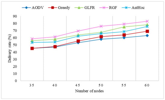
Figure 17.
The effect of the number of nodes on the delivery rate.
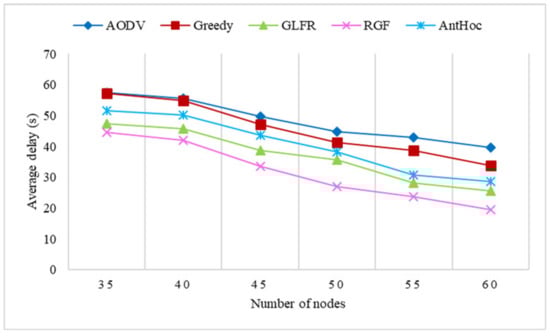
Figure 18.
The effect of the number of nodes on the average delay.
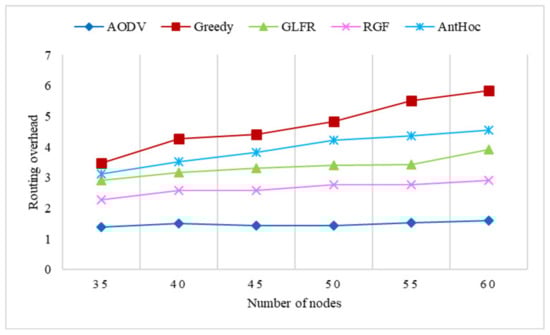
Figure 19.
The effect of the number of nodes on routing overhead.
Figure 17 demonstrates that as the number of nodes in the network increased, the weaker the network sparsity became; therefore, the delivery rate for all protocols improved significantly. For ADOV, the increase in the number of nodes made the network less prone to segmentation and so improved the delivery rate, but the lack of location awareness and the high dynamics of the topology still left a significant number of packets unnecessarily lost during transmission, so the improvement to AODV was the smallest of the four protocols. For the greedy, GLFR, and AntHocNet routing protocols, the increase in the number of nodes reduced the probability of routing holes in the network, so that forwarding could be executed more smoothly, and the delivery rate was higher than that of AODV. RGF relied more on greedy forwarding to transmit packets in highly dynamic networks, so the improvement was similar to that of greedy. Because it could rely on projection face forwarding to jump out of routing holes, the final delivery rate was higher.
As can be seen in Figure 18, the average delay of all protocols decreased significantly with an increase in the number of nodes, which is related to an increase in the delivery rate of these protocols. For AODV and greedy, the increase in the number of nodes allowed the existence of multiple paths to the destination node in the network, and even if the current route was broken, a new transmission path could be found, reducing the delay waiting in between due to the retransmission of control messages. For GLFR and AntHocNet, the increase in the number of nodes made packet forwarding less prone to encountering local minima, and route holes existed for shorter periods of time, thus reducing the waiting time for hole recovery and decreasing the latency. The increase in RGF with the number of nodes allowed the reactive mechanism to have the opportunity to establish more stable transmission paths, and greedy forwarding could be performed more smoothly.
The variation in the routing overhead with the number of nodes is shown in Figure 19. With an increase in the number of nodes, the routing overhead grew rapidly for greedy, with almost no growth for AODV and only a small increase for RGF, GLFR, and AntHocNet. For AODV, since route discovery required the network-wide flooding of RREQs, the increase in the number of nodes led to an increase in the number of flooded RREQ messages in the network, but because the delivery rate also increased, the routing overhead remained essentially the same. For greedy, it was clear that the number of successfully received packets did not keep up with the number of control packets as the number of nodes increased due to the need to flood HELLO messages across the network, so the routing overhead increased the most. In contrast, GLFR, RGF, and AntHocNet did not require network-wide flooded HELLO messages, so the growth in the routing overhead was lower than that of greedy.
The experimental results for node number changes are basically close to the results for the node speed changes. From the experimental results, it can be seen that RGF has obvious advantages over AODV, greedy, PSO-GLFR, and AntHocNet in terms of delivery rate, average end-to-end delay, and routing overhead in a three-dimensional high-dynamic topology, at a low density, and when there is an uneven distribution of nodes in the flight ad hoc network. In the high-speed and low-density scenarios, the RGF routing performance improved the communication ability of the FANET.
6. Conclusions
In this paper, the RGF routing protocol was proposed. Because of the high-dynamic topology and low density of nodes, the existing routing protocols could not provide a good performance. In order to make up for the shortcomings of a single forwarding strategy, multi-strategy forwarding can effectively reduce the packet waiting delay caused by the need for re-routing. Among them, reactive mechanism forwarding is provided by a reactive mechanism based on the network topology, such as AODV. The reactive mechanism is not only used for packet forwarding, but also for reactive location services, and it improves the efficiency of protocol operations. On the other hand, because the location service of active flooding provides the location information of neighbor nodes, when the reactive path is interrupted and the forwarding of the reactive mechanism cannot continue, it can quickly switch to greedy forwarding based on geographical location, which ensures the continuous transmission of data packets and avoids the impact of path interruption. When greedy forwarding encounters a local minimum problem, it can switch to projection face forwarding for recovery. In order to reduce the path expansion problem caused by projection face forwarding, a minimum local node will also start reactive mechanism construction, which can jump out of the routing hole to switch to reactive mechanism forwarding.
Author Contributions
Conceptualization, N.X. and X.C.; methodology, T.C., N.X., and Y.L.; software, F.L. and K.L.; validation, X.C., T.C., and F.L.; formal analysis, F.L.; investigation, N.X.; resources, X.C.; data curation, K.L.; writing—original draft preparation, N.X.; writing—review and editing, Y.L.; visualization, T.C.; supervision, Y.L.; project administration, X.C.; funding acquisition, N.X. All authors have read and agreed to the published version of the manuscript.
Funding
This research was funded by the National Key Research and Development Program of China, grant number 2019YFB1803100.
Informed Consent Statement
Not applicable.
Data Availability Statement
The data presented in this study are available on request from the corresponding author.
Conflicts of Interest
The authors declare no conflict of interest.
References
- Tang, Y.; Miao, Y.; Barnawi, A.; Alzahrani, B.; Alotaibi, R.; Hwang, K. A joint global and local path planning optimization for UAV task scheduling towards crowd air monitoring. Comput. Netw. 2021, 193, 107913. [Google Scholar] [CrossRef]
- Chang, B.; Tang, W.; Yan, X.; Tong, X.; Chen, Z. Integrated Scheduling of Sensing, Communication, and Control for mmWave/THz Communications in Cellular Connected UAV Networks. IEEE J. Sel. Areas Commun. 2022, 40, 2103–2113. [Google Scholar] [CrossRef]
- Xie, Z.; Song, X.; Cao, J.; Qiu, W. Providing Aerial MEC Service in Areas Without Infrastructure: A Tethered-UAV-Based Energy-Efficient Task Scheduling Framework. IEEE Internet Things J. 2022. [Google Scholar] [CrossRef]
- Sajid, M.; Mittal, H.; Pare, S.; Prasad, M. Routing and scheduling optimization for UAV assisted delivery system: A hybrid approach. Appl. Soft Comput. 2022, 126, 109225. [Google Scholar] [CrossRef]
- Frew, E.W.; Brown, T.X. Networking Issues for Small Unmanned Aircraft Systems. J. Intell. Robot. Syst. 2009, 54, 21–37. [Google Scholar] [CrossRef]
- Bekmezci, İ.; Sahingoz, O.K.; Temel, Ş. Flying Ad-Hoc Networks (FANETs): A survey. Ad Hoc Netw. 2013, 11, 1254–1270. [Google Scholar] [CrossRef]
- Durocher, S.; Kirkpatrick, D.; Narayanan, L. On routing with guaranteed delivery in three-dimensional ad hoc wireless networks. Wirel. Netw. 2010, 16, 227–235. [Google Scholar] [CrossRef]
- Gankhuyag, G.; Shrestha, A.P.; Yoo, S.J. A novel directional routing scheme for flying ad-hoc networks. In Proceedings of the International Conference on Information and Communication Technology Convergence, Jeju Island, Korea, 19–21 October 2016. [Google Scholar]
- Shirani, R.; St-Hilaire, M.; Kunz, T.; Zhou, Y. Combined Reactive-Geographic routing for Unmanned Aeronautical Ad-hoc Networks. In Proceedings of the Wireless Communications and Mobile Computing Conference, Shanghai, China, 27–31 August 2012. [Google Scholar]
- Maistrenko, V.A.; Alexey, L.V.; Danil, V.A. Experimental estimate of using the ant colony optimization algorithm to solve the routing problem in FANET. In Proceedings of the International Siberian Conference on Control and Communications, Moscow, Russia, 12–14 May 2016. [Google Scholar]
- Leonov, A.V. Application of bee colony algorithm for FANET routing. In Proceedings of the 2016 17th International Conference of Young Specialists on Micro/Nanotechnologies and Electron Devices, Erlagol, Altai, Russia, 30 June–4 July 2016. [Google Scholar]
- Leonov, A.V. Modeling of bio-inspired algorithms AntHocNet and BeeAdHoc for Flying Ad Hoc Networks (FANETS). In Proceedings of the International Scientific-Technical Conference on Actual Problems of Electronics Instrument Engineering, Novosibirsk, Russia, 3–6 October 2016. [Google Scholar]
- Rovira-Sugranes, A.; Razi, A. Predictive routing for dynamic UAV networks. In Proceedings of the IEEE International Conference on Wireless for Space and Extreme Environments, Montréal, QC, Canada, 10–12 October 2017. [Google Scholar]
- Li, X.; Huang, J. ABPP: An Adaptive Beacon Scheme for Geographic Routing in FANET. In Proceedings of the International Conference on Parallel and Distributed Computing, Applications and Technologies, Taipei, Taiwan, 18–20 December 2017. [Google Scholar]
- Zhu, Y.; Huang, Q.; Li, J.; Wu, D.O. Design and evaluation of airborne communication networks. In Proceedings of the Seventh International Conference on Ubiquitous and Future Networks, Sapporo, Japan, 7–10 July 2015. [Google Scholar]
- Qingwen, W.; Gang, L.; Zhi, L.; Qian, Q. An adaptive forwarding protocol for three dimensional Flying Ad Hoc Networks. In Proceedings of the International Conference on Electronics Information and Emergency Communication, Beijing, China, 14–16 May 2015. [Google Scholar]
- Zhong, D.; Wang, Y.; Zhu, Y.; You, T. An Aeronautical Ad Hoc Network routing protocol based on air vehicles movement features. In Proceedings of the International Conference on Applied Electromagnetics and Communications, Dubrovnik, Croatia, 19–21 September 2016. [Google Scholar]
- Chen, L.; Ruijuan, Y.; Meirong, H. Ad hoc high-dynamic routing protocol simulation and research. Wirel. Commun. Netw. Appl. 2016, 348, 399–408. [Google Scholar]
- Kout, A.; Labed, S.; Chikhi, S.; Bourennane, E.B. AODVCS, a new bio-inspired routing protocol based on cuckoo search algorithm for mobile ad hoc networks. Wirel. Netw. 2018, 24, 2509–2519. [Google Scholar] [CrossRef]
- Wang, F.; Chen, Z.; Zhang, J.; Zhou, C.; Yue, W. Greedy Forwarding and Limited Flooding based Routing Protocol for UAV Flying Ad-Hoc networks. In Proceedings of the 2019 IEEE 9th InternationalConference on Electronics Information and Emergency Communication, Beijing, China, 12–14 July 2018. [Google Scholar]
- Choi, S.; Hussen, H.R.; Park, J.; Kim, J. Geolocation-Based Routing Protocol for Flying Ad Hoc Networks (FANETs). In Proceedings of the 2018 Tenth International Conference on Ubiquitous and Future Networks (ICUFN), Prague, Czech Republic, 3–6 July 2018. [Google Scholar]
- Darabkh Khalid, A.; Alfawares, M.G.; Althunibat, S. MDRMA: Multi-data rate mobility-aware AODV-based protocol for flying ad-hoc networks. Veh. Commun. 2019, 18, 100163. [Google Scholar] [CrossRef]
- Mahmud, I.; Cho, Y. Adaptive Hello Interval in FANET Routing Protocols for Green UAVs. IEEE Access 2019, 7, 63004–63015. [Google Scholar] [CrossRef]
- Yang, H.; Liu, Z.Y. An optimization routing protocol for FANETs. Eurasip J. Wirel. Commun. Netw. 2019, 2019, 120. [Google Scholar] [CrossRef]
- Zheng, Z.; Sangaiah, A.K.; Wang, T. Adaptive Communication Protocols in Flying Ad Hoc Network. IEEE Commun. Mag. 2018, 56, 136–142. [Google Scholar] [CrossRef]
- Nayak, A.; Stojmenovic, I. Wireless Sensor and Actuator Networks: Algorithms and Protocols for Scalable Coordination and Data Communication; Wiley-Interscience: Hoboken, NJ, USA, 2010. [Google Scholar]
Publisher’s Note: MDPI stays neutral with regard to jurisdictional claims in published maps and institutional affiliations. |
© 2022 by the authors. Licensee MDPI, Basel, Switzerland. This article is an open access article distributed under the terms and conditions of the Creative Commons Attribution (CC BY) license (https://creativecommons.org/licenses/by/4.0/).