Abstract
In recent years, the use of synchronous generators (SGs) has been displaced due to the increased use of renewable energy sources. These types of plants mostly use power electronic converters to connect to power grids, which, due to their mode of operation, cannot provide the same services. This paper analyzes the synchronization of Grid-Forming converters (GFM) without phase-locked loop (PLL) through the active power control loop. Stability analysis shows that when increasing the emulated moment of inertia in a voltage source converter (VSC) using grid-forming control, the system becomes oscillatory. The paper proposes a novel compensation mechanism in order to damp the system oscillation, allowing the implementation of inertia emulation. Finally, the real-time implementation is executed using a Hardware in the Loop experimental set-up. The response of VSC under grid disturbances is simulated in a real time simulator, while the proposed control system is implemented in a real-time controller platform.
1. Introduction
Nowadays, it is a well-known fact that the high penetration of renewable power plants has completely changed the electrical generation model. Only 25 years ago, the vast majority of power plants were based on thermal, hydraulic and nuclear energy sources that used a conventional SG as electromechanical power converters to grid connection. Unlike this concept, renewable energy (wind farms and photovoltaic power plants) has arisen as an alternative to traditional power stations, but with some important particularities. On the one hand, renewable energy sources (RES) interact with the grid through inverter-based resources (IBRs) that differ from conventional SGs in that they do not behave as voltage sources but as constant power sources [1].
According to the latest studies [2], RES hourly penetration scenarios close to 100% are already taking place in some power systems. It seems clear that in a system in which most or all resources are inverter-based, these must contribute to grid services to ensure system stability and reliability. The displacement of SGs by IBRs can result in degrading power system stability and operability if IBRs do not provide the same services as SGs. Ancillary services required to operate a stable and secure grid can be grouped into different categories, such as: inertial response, frequency control, voltage control, system strength and power system restoration, among others [3].
Unlike SGs, inverter-based RES currently require a stable voltage at their terminals to exchange active power with the network converting the variable energy resource into electrical energy. Likewise, they also have the capacity to exchange reactive power, contributing to power factor control and voltage regulation. This requirement of having a stable voltage at their terminals is guaranteed mainly by the voltage and frequency regulation provided by SGs. For that reason, these types of converters are usually named as grid-following (GFL) converters. Its operating principle is based on the estimation of the magnitude and phase of the voltage at their terminals by means of a Phase-Locked Loop (PLL). Although this voltage measurement and estimation technique has been improved over the years, allowing the proper operation of GFL converters in grids with a high content of voltage harmonics or imbalances, GFL converters are not adequate for operation on weak grids with low short-circuit power. Furthermore, GFL converters have a reduced ability to provide inertial response and they are not able to operate in islanded mode, so they cannot contribute to the restoration of the power system in the event of a blackout [4]. GFL converters cannot provide certain services required for the electrical system operation, therefore a new type of technology, grid-forming GFM converters, have been recently developed. Its principle of operation is based on reproducing the same behavior as a SG, keeping the module and phase of its internal voltage controlled, even during sub-transient periods. GFM converters are able to operate in isolated mode and in networks with very low short-circuit power, contributing to the power system restoration service. Furthermore, they are able not only capable of damping power oscillations but also of providing inertial response [5].
Different grid-forming converter implementations can be found in the bibliography. According to its operation principles, they can be grouped into three categories [6]. First category corresponds to the droop control concept which enables the parallel operation of multiple converters emulating the governor action of SGs. This category can be subdivided into a frequency-based droop [7,8,9,10,11,12], angle-based droop [13,14,15] or power synchronization control (PSC) [16,17]. One of the serious shortcomings of the droop controller is the lack of inertia support. Recently, new GFM controllers that incorporate the inertial and damping properties of SGs have been proposed, which have been included in the second category named synchronous-machine-based control. The first attempt at emulating the behavior of a SG was introduced as a concept called virtual synchronous machine (VISMA) [18,19], reproducing by control the complete dynamic equations of a SG. Some GFM controllers emulate the SG’s swing equation [20,21,22,23,24,25,26,27,28,29,30], others operate as virtual synchronous generators (VSG) with augmented capabilities [31,32,33,34,35,36,37,38] in order to achieve better damping and improved transient stability. Another concept in this category is the Synchronverter that completely mimics the dynamics of a SG through control, including the electrical machine, speed governor and voltage regulator [39,40,41,42,43,44]. In [45,46,47], a novel GFM control strategy named matching control is presented. This new controller is designed to match the electromechanical energy transfer of SGs by utilizing the DC-link voltage of the converter. Apart from these two categories, some other non-linear methods are also proposed such as the virtual oscillation-based method [48,49,50,51,52,53,54,55,56]. The virtual oscillator controller (VOC) is a non-linear control strategy which makes a converter reproduce the dynamic of a weakly nonlinear limit-cycle oscillator, allowing converters to synchronize with each other from any arbitrary initial condition without the need for any communication.
Due to the inherent behavior of a GFM converter as a voltage source, this technology may encounter overcurrent problems under large grid disturbances such AC faults, phase jumps or large frequency deviations. For these cases, there are different current limiting strategies which are based on adding a current limiter block between voltage and current control [57,58,59], or more sophisticated ones based on virtual impedance control [60] and acting over the internal frequency on the power synchronization loop, avoiding the possibility of the GFM inverter becoming unstable.
This paper is focused on providing inertial response by a GFM converter using an internal power stabilizer in order to damp any power oscillation produced by the converter during grid frequency changes. These power oscillations are more pronounced when a high constant inertia and low damping factor are used without any stabilizer. GFM converters are considered a promising solution to address the challenges associated with the provision of emulated inertial response to support the operation of converter-dominated power systems. This inertia support can also be provided through a synchronous condenser (SC); however, this option presents some drawbacks in comparison to the GFM converter, operating as a static synchronous condenser [61]. Conventional SCs based on a rotating synchronous machine is a well-known and mature technology, but its moment of inertia is constant and cannot be changed once it has been installed. On the contrary, a static SC based on the GFM converter can modify its inertial response by control and modifying the required DC energy. In any case, this option is much more flexible than a conventional SC.
This paper is organized as follows. In Section 2 the system description including a VSC along with their voltage and current regulators is presented. Section 3 shows the GFM control strategy based on a power synchronization loop with a power stabilizer in order to design a static synchronous condenser providing inertial response. In Section 4, a current limiting strategy of the grid-forming converter is presented. Finally, in Section 5, the results of a comprehensive real time simulation are shown and discussed. The complete GFM control is executed using a hardware in the loop experimental set-up connected to a real-time digital simulator, where the response of the VSC operating as a static SC is analyzed under different grid disturbances. In Section 5, the final conclusions of this work are presented.
2. System Description and Control
This section describes the elements of a grid-connected voltage source converter, its dynamic equations and its control when operating as a grid-forming converter. Figure 1 illustrates a single line diagram of a VSC connected to the point of common coupling (PCC) through an LCL filter which includes a step-up transformer. The voltage at the DC bus terminals is , and the input current is .
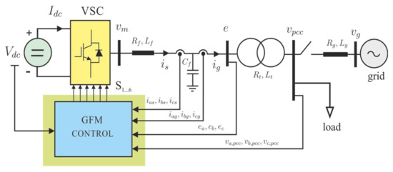
Figure 1.
System description of a GFM-controlled VSC connected to a grid.
The VSC is controlled by measuring the three-phase current output of the converter, ,, and the grid currents, ,. At the AC side, voltages in the capacitor , ,, and at the PCC ,, are also required. At the DC side, the voltage is also measured. All these signals are the inputs of a GFM control block that determines the switching pattern from which the output voltages of the VSC , are generated. A breaker is connected between the PCC and the grid, and its state determines the operation mode of the VSC (on: grid connected, off: islanded). At the PCC, a local load is connected. The grid is modeled through a Thévenin equivalent formed by a three-phase voltage source , of constant frequency (rad/s), and an internal impedance with resistance and reactance .
2.1. Dynamic Equations
The dynamic equations of the VSC correspond to its LCL filter. These equations are represented in a rotating dq-axes system whose angular position, with respect to a stationary reference system, , is determined by the GFM control. Using a vector representation in the dq-axes, the following dynamic equations of currents in the inductive filter, , are obtained
Following the same procedure as above, the dynamic equations of dq voltages on the capacitor are
As in (1) and (2), a similar representation for the variable states and can be obtained. In this case, the dynamic equations are as follows
2.2. Voltage and Current Controllers
A GFM-controlled VSC acts as a voltage source defined by its module, , and its angle . Figure 2 shows the voltage and current control blocks to achieve the voltage source defined by and up to obtaining the switching pattern of the VSC. Since the control is performed in the dq-axes, all instantaneous voltage and current variables are initially passed through a Park transformation ) to obtain their dq components. Note that the angle used for the Park transformation corresponds to the angle reference of the voltage source. Its value will be determined through an active power synchronization loop, as explained in the following sections. Certainly, this is a differentiating aspect between GFM control and grid-following methods that use a PLL to determine this angle .

Figure 2.
Grid-forming voltage and current control blocks.
In the outer voltage controller, the d-axis voltage reference, is compared to , and likewise the q-axis reference, which is equal to zero, is compared to . This means that the GFM control tries to align the voltage vector to the d-axis of the rotating dq reference system. The difference in these signals on each axis are inputs of two PI regulators that determine currents and , respectively. According to (3) and (4), these dq currents components are compensated by two cross-coupling terms, and , which correspond to current dq-components on the capacitor, and by two additional current terms and . When these compensation terms are applied, dynamics of PI regulators improve significantly.
A similar structure was used for the inner current controller. In this case, inputs are and , which are compared to the actual components and . These differences establish the voltage components and as the outputs of two PI regulators. As in the voltage controller, these components are obtained by adding two compensations terms. For the d-axis, this term is , and for the q-axis . Later on, these voltage components and are divided by (both magnitudes in p.u.) in order to obtain and , which are the d and q amplitude modulation indexes, respectively. By applying an inverse Park transformation, , the amplitude modulation indices per phase are obtained. Finally, through a pulse width modulation (PWM) of these three-phase magnitudes the switching pattern is achieved.
2.3. Reactive Power Controller
As shown in Figure 2, the internal voltage reference is defined by its module, , and its angle . These references are usually calculated through external power controllers, so that the VSC can be operated as a PQ node, or eventually as a PV node if the reactive power controller is replaced by a voltage controller.
Figure 3 shows a reactive power controller. The controller is based on the well-known droop control where the voltage magnitude is obtained as the product of a gain constant, , times the difference between the reactive power reference,, and its actual value, , plus an initial voltage
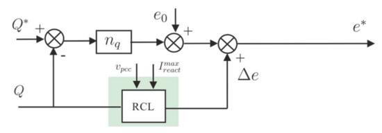
Figure 3.
Reactive power controller.
This equation can be interpreted as follows. When the reactive power is greater than its reference, , it means that the voltage reference is reduced below the voltage value so that the reactive decreases, achieving a steady-state value close to the reactive power reference . Since this is a proportional controller, this system can reach a stable operating point where and are different. Although this gives rise to an error in steady state, the advantage of this method is that several VSC converters can contribute to the voltage control by sharing reactive power proportionally to their rated power.
Figure 3 shows how the voltage reference is affected by a signal . This signal is different from zero only when the reactive current, , is out of limits. One way of limiting the reactive current is achieved by acting over the voltage reference; decreasing when is greater than its maximum limit (), or increasing when it is lower than a minimum value (usually ). In this figure, RCL represents the reactive current limiting block, shown in Figure 4.
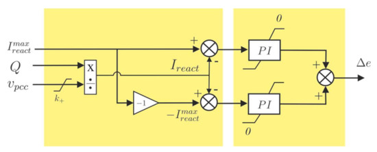
Figure 4.
Reactive current limiting (RCL) block.
The reactive power injected by the VSC can be expressed as the product of voltage and current dq components as
where has been expressed in p.u. The reactive power can also be represented in terms of the product of the reactive current and the voltage module at the PCC as
Figure 4 shows the reactive current limiting block mentioned before. According to (9), the reactive current, , is obtained by dividing by the module of the voltage at PCC . To avoid numerical issues when , is limited to a value grater than . In case the reactive current starts to be out of limits, e.g., when , the PI regulator generates a negative , decreasing the voltage reference and therefore reducing . On the other hand, when regulator’s output establishes that .
A similar reasoning can be made for the lower limit . In this case, when the reactive current is out of limits, () the PI regulator generates a positive , and, as before, if (). A clear advantage of this type of limiter is that it only operates when the reactive current is out of limits. Otherwise, the voltage reference is calculated by a reactive power controller, or by a PCC voltage regulator in case of operating in isolated mode.
2.4. Active Power Synchronization Loop
The active power synchronization loop is shown in Figure 5. The block diagram corresponding to the swing equation of the synchronous generator is expressed as a differential equation as follows
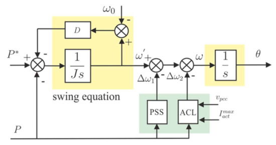
Figure 5.
Active power synchronization loop.
By integrating (10) the internal frequency is obtained, where and are the reference and the measured active power of the VSC converter at PCC, respectively. The nominal frequency is represented by , being the moment of inertia, twice the inertial constant , expressed in seconds, and the damping factor which, in p.u., is inverse to the droop constant , so that .
The internal frequency is integrated to obtain the control angle of the rotating dq axes. In fact, this internal frequency is corrected by signals and , which are the outputs of a power system stabilizer (PSS), and an active current limiting block (ACL), respectively. So, the control angle is obtained as
As before, the active power generated by the VSC in this case is expressed, in p.u., as the product of voltages and currents dq components as
and as the product of the voltage magnitude and the active current
Like in the previous case, the active current limiting block modify the control angle to avoid system instability if reaches a value greater than or lower than . Figure 6 shows this ACL block.
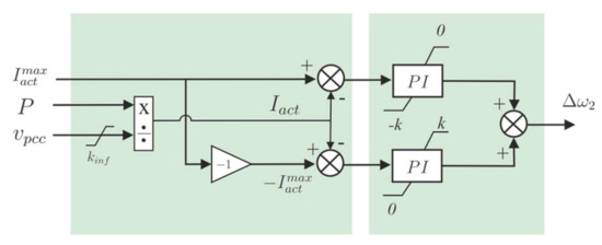
Figure 6.
Active current limiting (ACL) block.
Its structure and control logic are similar to the RCL block but in this case using the active current obtained from . Furthermore, PI limits are saturated to a value when and when .
The next section presents the design and parameter tuning of the PSS shown in Figure 5.
3. Power System Stabilizer
This section discusses the design and tuning of a power system stabilizer (PSS) integrated in the active power synchronization loop as it shown in Figure 5, analyzing the dynamic response of the control angle, , with respect to changes in the active power reference or on the grid frequency, . These are increment variables, or small signals around an equilibrium point. In particular, is the angular position deviation of the dq axes with respect to a reference frame rotating at rad/s. Likewise, is a deviation from the power reference on the equilibrium point, and a frequency deviation from the grid frequency . Overline notation on these variables means that they are expressed in p.u.
The dynamic relationship between under changes on and is achieved by following a three-step process. Firstly, linearizing (10) around an operating point yields
from which a first-order transfer function can be defined as
where represents the moment of inertia of the virtual synchronous generator (VSG) in seconds and the damping constant in p.u. The reciprocal of is the droop constant
which represents, in p.u., the coefficient between the variation in the frequency with respect to the nominal frequency and the variation in power with respect to the nominal power.
The second step is to calculate the angular increment as a function of and as follows
Its dynamic response depends on the difference between the internal frequency and the grid frequency. When the VSC is synchronized, the power-angle, , is constant and both frequencies, and , are equal.
Figure 7 shows the block diagram of the active power synchronization loop where the dependency of with through the function ) is shown.
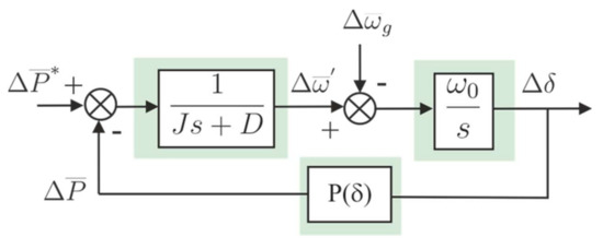
Figure 7.
Block diagram of the active power synchronization loop.
It is a well-known fact that the active power transmitted between two nodes connected through a line is inversely proportional to the line reactance, and directly proportional to the voltage magnitude of the nodes and to , being the angular difference between these two nodes. Applying this definition to the active power transferred by the VSC of Figure 1 yields an expression for the active power as
where is the reactance of the output filter. By considering the increments in this equation, the following linear relationship between power and angle is obtained
where is the synchronizing constant and its value is obtained by applying to (18) the partial derivative of with respect to at the point of equilibrium “0”
From the block diagram in Figure 7, the transfer function between and (considering ) can be obtained as follows
Similarly, the transfer function between and when the power reference is constant can also be achieved. In this case, the power increment is equal to
considering that the internal frequency increment can be expressed in terms of as
Substituting (23) in (22) yields
and reordering, it can be expressed as the sum of two terms
The first one corresponds to the inertial response, where the product is defined as the rate of change in frequency (RoCoF), so that the power injected in steady-state due to the inertial response is equal to
In other words, the power exchanged by the VSC-GFM during an inertial response is proportional to the moment of inertia, , and to the RoCoF. Note that the power response has an opposite sign to frequency variations.
Considering now the second term and operating in the same way, the power increment in steady-state due to the droop response is
Considering an application where the GFM-VSC presents only an inertial response (= 0), the dynamics under a change in frequency have two complex-conjugated poles on the imaginary axis, with a critically stable response and an oscillatory response, and the relationship between and is equal to
For this inertial response to be acceptable, a PSS must be included in the dynamics. Figure 8 shows the proposed PSS integrated in the active power synchronization loop.
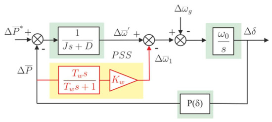
Figure 8.
PSS integration in the power synchronization loop.
Representing (28) as a differential equation in terms of yields
The PSS transfer function shown in Figure 8 can be expressed as
and considering that according to (19), is equal to and the relationship between the angle and the frequency, (30) can be represented as follows
By adding (29) and (31), the following expression is obtained
that represents an equation similar to (28)
but with new values of inertia constant , and damping factor whose expressions are
Note that depends on the PSS time constant , but its influence is not relevant since is usually higher than . Typically, inertia constant values are in the order of seconds, while is usually lower than 0.5 s. In the case of the damping constant , its value is mainly defined by the gain constant . Once the plant is linearized, is obtained, time constant is defined and is chosen to obtain a certain damping constant When there is no PSS, and equation (33) is the same as (28), being and .
Figure 9 shows the pole placement of the transfer function indicated in (33) as a function of with the following parameters: the synchronizing constant is equal to 6.67 p.u. considering a reactance of 0.15 p.u. and at the operating point p.u, and the power angle ; The PSS time constant is ms and rad/s.
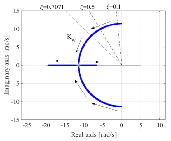
Figure 9.
Poles loci of the transfer function under variation.
As shown in Figure 9, when the damping factor is practically zero, the poles are complex conjugated and placed on the imaginary axis. When increases, the poles follow a circular path in the negative half-plane until the damping ratio > 1, from where the poles are placed on the negative real axis.
The natural frequency and the damping ratio of a normalized second order function of Equation (25) are calculated in terms of and as follows
The PSS parameters are adjusted by defining the time constant and the PSS gain, for a specific damping ratio . Figure 10 shows as a function of J, considering that D = 0 and (poles with equal real and imaginary part). is equal to 6.67 p.u. and rad/s. As shown in the figure, when s, p.u. if s and p.u. for s. So, in order to achieve the same damping ratio, the lower the time constant of the PSS, the higher its gain is.
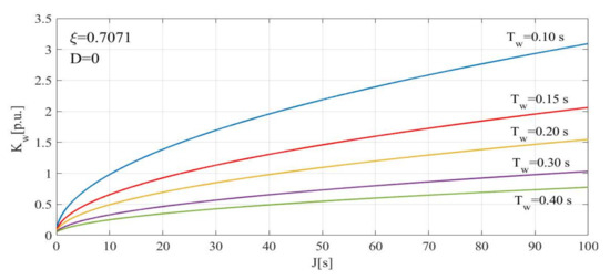
Figure 10.
as a function of J for different values.
Figure 11 shows the response of GFM-VSC with and without PSS under a frequency drop of 2.5 Hz with a RoCoF of 0.3 Hz/s designed for an inertia constant and . This figure clearly shows the effect of the PSS, stabilizing the system response against a frequency variation.
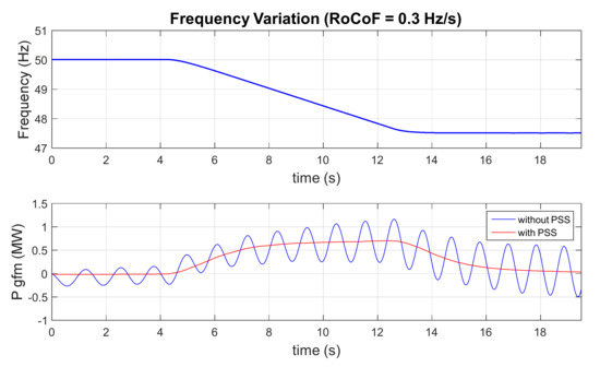
Figure 11.
Active power provided by the VSC at a frequency variation with and without PSS.
Figure 12 shows the power provided by a 2 MW-VSC including a PSS under the same frequency variation for different values of the inertia constant . To obtain these results, the converter was connected to an ideal network and a frequency drop of 2.5 Hz with a RoCoF of 0.3 Hz/s was applied. According to (26), the active power exchange by a GFM-VSC, designed to provide inertial response, is proportional to the inertia constant and to the rate of change in frequency. As shown in Figure 12, the active power increases when the frequency is reduced at a constant rate of 0.3 Hz/s. Only when the frequency is changing is the active power different from zero. In the interval where the frequency is changing, the higher the inertia, the higher the power generated.
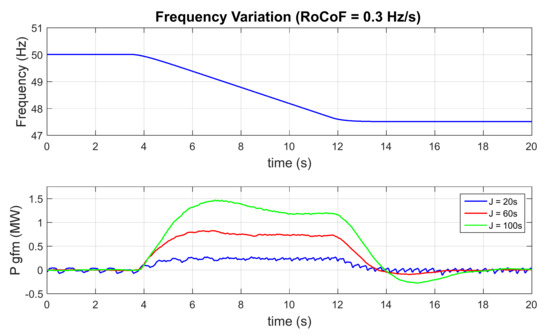
Figure 12.
Active power provided by the VSC at a frequency variation for different J values.
The results shown in Figure 12 were obtained using the Hardware in the Loop experimental set-up, which will be described in the next section.
4. Simulations Results
This section presents the performed tests, which include synchronization with the grid, response to load changes, operation in islanded mode and an analysis of the harmonic components of the converter voltage and current. In addition, the operation of the current limiter was also tested. For this purpose, the plant illustrated in Figure 13 has been modelled in RSCAD. This system consists of a SG that can be connected or disconnected to the PCC through a main switch (SW). The load can also be varied in order to check the converter behavior by means of another manually controlled switch, not represented in the scheme.
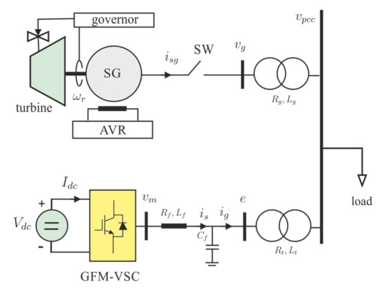
Figure 13.
Schematic of the plant designed in RSCAD.
All the results presented in this section were obtained using the Hardware in the Loop experimental set-up shown in Figure 14, which includes the Real Time Digital Simulator (RTDS) on the left side of the image and the real-time controller (dSpace) on the right side.
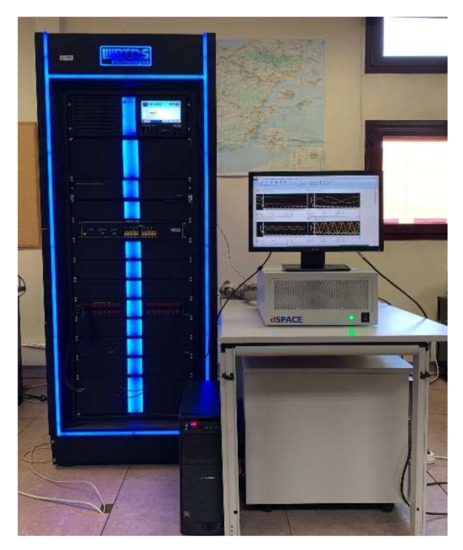
Figure 14.
Hardware in the Loop experimental set-up.
The parameters used to configure the model in RSCAD are given in Table A1 of Appendix A. Likewise, the parameters of the active power synchronization loop are given in Table A2 of Appendix B.
4.1. Synchronization
The state of the main switch is represented in the upper plot of Figure 15. The middle plot shows the phase a of the grid voltages and the converter voltages. Only one phase is represented to improve the presentation of the synchronization moment. Finally, the lower graph shows the error between these voltages (). Before closing the main switch, the grid and the converter voltages are almost in phase and with a similar amplitude. At time t = 0.06 s, the main switch closes and the voltages of the GFM converter (in blue) and the grid (in red) are completely synchronized and the error becomes 0.
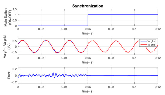
Figure 15.
Grid synchronization signal and GFM converter voltages.
4.2. Load Change
Once the synchronization is verified, a load change is applied to check the response to a load disturbance. Figure 16 shows the load change, followed by the system frequency response and the active power supplied by the converter to support the system frequency.
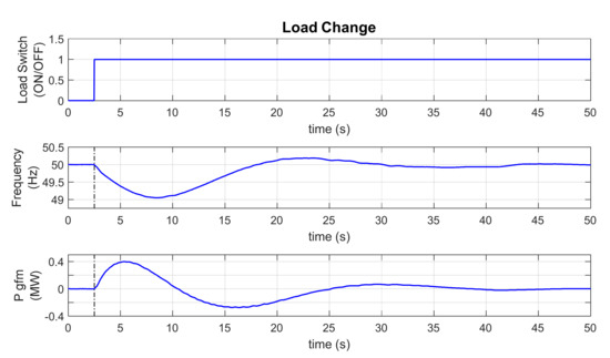
Figure 16.
Power contribution by the converter at load change.
As soon as the load change occurs, the frequency decreases and, at the same time, the converter starts to inject active power to the grid. Likewise, when the grid begins to increase its frequency to reach 50 Hz again, the converter absorbs power to stabilize the system. Clearly, the converter power follows the frequency derivative to support the system frequency stability.
Figure 17 shows the comparison between the frequency response of the SG with and without a Grid-Forming converter support. The converter clearly helps to improve the RoCoF from 0.8 to 0.15 Hz/s, as well as the frequency nadir, which improved from 48.25 Hz to 49 Hz when the VSC was connected.
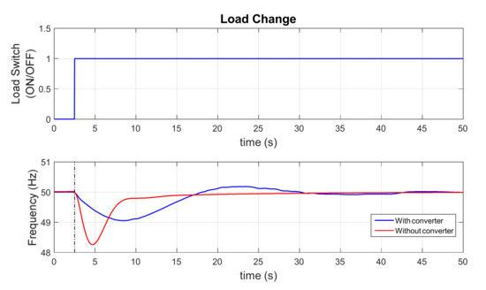
Figure 17.
Comparison of frequency response with and without Grid-Forming converter.
4.3. Current Limiter
To test the operation of the current limiter, the converter was connected to an ideal source as in Section 3 and a frequency drop of 2.5 Hz with a RoCoF = 1 Hz/s was applied. In this case, a more abrupt frequency change was applied to reach the converter current limit. Figure 18 shows how during the frequency variation, the converter injects power to the grid which causes an increase in the current, saturating it to its maximum value, set at 1.15 times the value of the base current ( = 2366.67 A, = 2721.67 A). The second graph shows the value of the current magnitude in p.u. and the last one, the instantaneous value of the three phase currents at the output of the converter, ,.
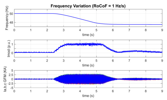
Figure 18.
Verification of the operation of the current limiter.
4.4. Islanded Operation Mode
The capability to operate as a voltage source when the converter switches from grid-connected to islanded mode is an operational requirement for GFM converters. For this test, once the generator and the converter are synchronized and the load is connected, the SG is disconnected from the grid in t = 0.5 s to check the converter’s islanding mode operational capability. As shown in Figure 19, once the main switch is open, the converter can maintain the system voltage and frequency.
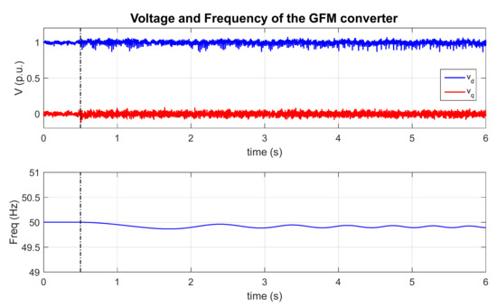
Figure 19.
Voltage and frequency during the transition to islanded mode.
Figure 20 shows the instantaneous phase voltages before and after opening the main breaker. As in Figure 19, the voltages are almost unchanged when the converter switches to islanded mode.
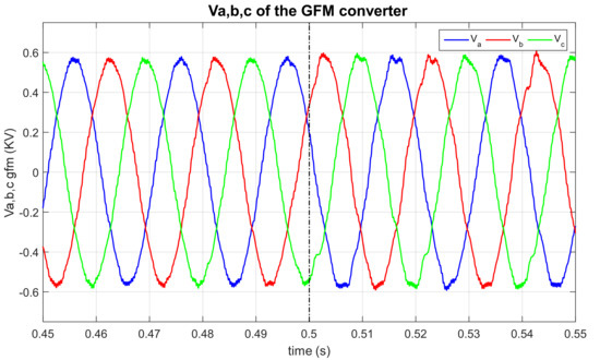
Figure 20.
Instantaneous phase voltages during the transition to islanded mode.
When a GFM converter switches to islanded mode, it must, in addition to keeping the voltage and frequency under control, generate the active and reactive power demanded by the load. System load is 1 MW, as can be seen in Figure 21. Initially, the VSC power command is null, but when the switch is open the VSC automatically provides the system load, (, while the generator stops supplying it (.
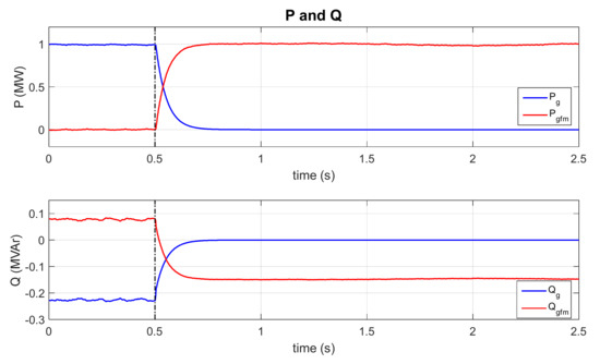
Figure 21.
Active and reactive powers during the transition to islanded mode.
The reactive power response is given in the lower graph. Similarly, when the converter switches to islanded mode, the SG stops supplying the system reactive power (), which must be supplied by the VSC ( approx.). Note that in this case, the final reactive power is not the same, because when the switch is open, the SG step-up transformer is also disconnected, changing the system reactive power demand.
Finally, Figure 22 shows the instantaneous phase currents of the grid in the upper graph and those of the converter in the lower graph. It can be clearly seen that the grid currents become zero when the breaker is open, while the converter currents increase to supply the system demand.
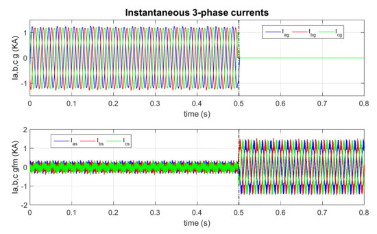
Figure 22.
Instantaneous 3-phase currents during the transition to islanded mode.
4.5. Harmonic Analysis
For the analysis, the converter was first synchronized with the grid and then a 0.5 p.u. active power setpoint (1 MW) was sent. Figure 23 shows the converter generated voltage measured at the capacitor terminals and the current of phase a of the converter in the steady state.
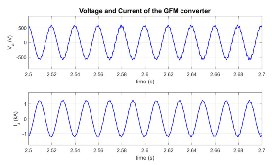
Figure 23.
Inverter voltage and current of phase a of the converter in steady state.
The harmonic spectrum measurements presented in Figure 24 were performed according to Section 7.3 of IEEE 1547 and were normalized with respect to current . The maximum harmonic current distortion limits in the percent of rated current for odd and even harmonics according to IEEE standards are represented in red and their values are given in Table A3 and Table A4 of Appendix C. Lastly, the Total Harmonic Distortion value was also included.
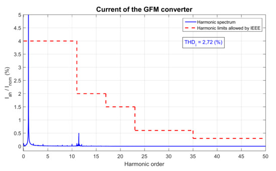
Figure 24.
Frequency analysis of harmonic components.
To improve the presentation of the harmonic spectrum, the current amplitude in the fundamental harmonic is shown cropped in width. As the value (2.72 %) is less than 5 % and the harmonics do not exceed the allowed limits, the model is operated according to IEEE 1547 standard.
5. Conclusions
The main conclusion of this paper, based on the results obtained in the tests, is that the proposed mechanism can correctly provide the inertia emulation. Instability is avoided through the proposed PSS.
For the case in which no primary regulation is provided (D = 0), the inclusion of the PSS causes the displacement of the poles located on the imaginary axis, significantly improving system stability. This paper also explains the effect of the inertia constant value in GFM stability. Higher values of decrease the speed of response of the system and increase the contribution of active power during frequency changes.
The findings of the paper were validated through a Hardware in the loop set-up in a real-time simulator. It was proved that the converter maintains the synchronism with the grid once it is synchronized and the main switch is closed. Furthermore, it was verified that the system provides active power following the changes in grid frequency, improving both the RoCoF and the nadir of the frequency change.
Finally, the converter’s ability to switch from grid-connected mode to islanded mode was also validated. The GFM converter is able to maintain a constant voltage and frequency, demonstrating its ability to work as a voltage source emulating the behavior of a synchronous generator, supplying active and reactive power demanded by the system load.
Author Contributions
Conceptualization, J.L.R.A. and S.A.; Methodology, J.L.R.A.; Software, J.D.; Validation, J.D., J.L.R.A. and J.E.-G.; Investigation, J.L.R.A. and S.A.; Data curation, J.L.R.A. and S.A.; Writing—original draft preparation, J.D. and J.L.R.A.; Writing—review and editing, J.E.-G. and S.A.; Visualization, J.D.; supervision, J.L.R.A., S.A. and J.E.-G. All authors have read and agreed to the published version of the manuscript.
Funding
This paper was supported by the Spanish Research Agency under project reference PID2019-106028RB-I00/AEI/10.13039/501100011033.
Conflicts of Interest
The authors declare no conflict of interest.
Appendix A
RSCAD Parameters
Table A1 shows all the parameters used to configure the system in RSCAD.

Table A1.
System parameters.
Table A1.
System parameters.
| Parameters | Value | Units |
|---|---|---|
| DC voltage of the VSC, | 1200 | V |
| Converter rated power, | 2 | MVA |
| Line to line rated voltage (RMS), | 690 | V |
| Filter inductance, | 0.113 | mH |
| Filter resistance, | 3.552 | mΩ |
| Filter capacitance, | 1 | mF |
| Nominal frequency, | 50 | Hz |
| Switching frequency, | 3 | kHz |
| Synchronization constant, | 6.67 | Hz/MVAr |
| Grid inductance, | 0.226 | µH |
| Grid resistance, | 7.104 | µΩ |
| Short-circuit ratio, SCR | 500 | |
| X/R ratio | 10 | |
| Synchronous generator rated power, | 4.5 | MVA |
| Synchronous generator Phase rated voltage, | 5 | kV |
| Frequency, | 50 | Hz |
| Inertia constant, | 2.5 | s |
| Stator leakage reactance, | 0.113 | p.u. |
| Unsaturated reactance, | 1.85 | p.u. |
| Unsaturated transient reactance, | 0.225 | p.u. |
| Unsaturated sub-transient reactance, | 0.2 | p.u. |
| Q-axis unsaturated reactance, | 1.74 | p.u. |
| Q-axis unsaturated transient reactance, | 0.306 | p.u. |
| Q-axis unsaturated sub-transient reactance, | 0.2 | p.u. |
| : power rating, | 2 | MVA |
| : rated line-line voltage primary, | 20 | kV |
| : rated line-line voltage secondary, | 0.69 | kV |
| : frequency | 50 | Hz |
| : power rating, | 4.5 | MVA |
| : rated line-line voltage primary, | 5 | kV |
| : rated line-line voltage secondary, | 20 | kV |
| : frequency | 50 | Hz |
Appendix B
Active Power Synchronization Loop Parameters
The values used in the active power synchronization loop are shown in Table A2.
Table A2.
Control loop parameters.
Table A2.
Control loop parameters.
| Parameters | Value | Units |
|---|---|---|
| Inertia constant, | 30 | s |
| Damping constant, | 0 | p.u. |
| PSS time constant, | 1.2 | s |
| PSS constant, | 0.01 | s |
Appendix C
IEEE Maximum Harmonic Current Distortion in Percent of Rated Current
Table A3.
IEEE 1547 Maximum odd harmonic current distortion in percent of rated current.
Table A3.
IEEE 1547 Maximum odd harmonic current distortion in percent of rated current.
| Percent (%) | |
|---|---|
| 4.0 | |
| 2.0 | |
| 1.5 | |
| 0.6 | |
| 0.3 | |
| Total rated current distortion (RTD) | 5.0 |
Table A4.
IEEE 1547 Maximum even harmonic current distortion in percent of rated current.
Table A4.
IEEE 1547 Maximum even harmonic current distortion in percent of rated current.
| Percent (%) | |
|---|---|
| 4.0 | |
| 2.0 | |
| 1.5 | |
| Associated range specified in Table A1 |
References
- Matevosyan, J.; MacDowell, J.; Badrzadeh, B.; Cheng, C.; Dutta, S.; Rao, S.D.; Gevorgian, V.; Green, T.; Howard, D.; Kong, D.; et al. Grid-Forming Technology in Energy Systems Integration. ESIG High Share of Inverter-Based Generation Task Force: Report. Available online: https://www.esig.energy/wp-content/uploads/2022/03/ESIG-GFM-report-2022.pdf (accessed on 20 June 2022).
- Christensen, P.; Andersen, G.K.; Seidel, M.; Bolik, S.; Engelken, S.; Knueppel, T.; Krontiris, A.; Wuerflinger, K.; Bülo, T.; Jahn, J. High Penetration of Power Electronic Interfaced Power Sources and the Potential Contribution of Grid Forming Converters. ENTSO-E: Report. Available online: https://euagenda.eu/upload/publications/untitled-292051-ea.pdf (accessed on 20 June 2022).
- Bialek, J.; Bowen, T.; Green, T.; Lew, D.; Li, Y.; MacDowell, J.; Matevosyan, J.; Miller, N.; O’Malley, M.; Ramasubramanian, D. System Needs and Services for Systems with High IBR Penetration. Global Power System Transformation Consortium (G-PST): Report. Available online: https://globalpst.org/wp-content/uploads/GPST-IBR-Research-Team-System-Services-and-Needs-for-High-IBR-Networks.pdf (accessed on 20 June 2022).
- Rosso, R.; Wang, X.; Liserre, M.; Lu, X.; Engelken, S. Grid-forming converters: Control approaches, grid-synchronization, and future trends-A review. IEEE Open J. Ind. Appl. 2021, 2, 93–109. [Google Scholar] [CrossRef]
- Rathnayake, D.B.; Akrami, M.; Phurailatpam, C.; Me, S.P.; Hadavi, S.; Jayasinghe, G.; Zabihi, S.; Bahrani, B. Grid Forming Inverter Modeling, Control, and Applications. IEEE Access 2021, 9, 114781–114807. [Google Scholar] [CrossRef]
- Zhang, H.; Xiang, W.; Lin, W.; Wen, J. Grid forming converters in renewable energy sources dominated power grid: Control strategy, stability, application, and challenges. J. Mod. Power Syst. Clean Energy 2021, 9, 1239–1256. [Google Scholar] [CrossRef]
- Chandorkar, M.C.; Divan, D.M.; Adapa, R. Control of parallel connected inverters in standalone AC supply systems. IEEE Trans. Ind. Appl. 1993, 29, 136–143. [Google Scholar] [CrossRef]
- Guerrero, J.M.; Vicuna, L.G.; Matas, J.; Castilla, M.; Miret, J. A wireless controller to enhance dynamic performance of parallel inverters indistributed generation systems. IEEE Trans. Power Electron. 2004, 19, 1205–1213. [Google Scholar] [CrossRef]
- De Brabandere, K.; Bolsens, B.; van den Keybus, J.; Woyte, A.; Driesen, J.; Belmans, R. A voltage and frequency droop control method for parallel inverters. IEEE Trans. Power Electron. 2007, 22, 1107–1115. [Google Scholar] [CrossRef]
- Guerrero, J.M.; de Vicuna, L.G.; Matas, J.; Castilla, M.; Miret, J. Output impedance design of parallel-connected UPS inverters with wireless load-sharing control. IEEE Trans. Ind. Electron. 2005, 52, 1126–1135. [Google Scholar] [CrossRef]
- Huang, L.; Xin, H.; Dörfler, F. H∞-control of grid-connected converters: Design, objectives and decentralized stability certificates. IEEE Trans. Smart Grid 2020, 11, 3805–3816. [Google Scholar] [CrossRef]
- Sharma, R.K.; Mishra, S.; Pullaguram, D. A robust H∞ multivariable stabilizer design for droop based autonomous AC microgrid. IEEE Trans. Power Syst. 2020, 35, 4369–4382. [Google Scholar] [CrossRef]
- Pogaku, N.; Prodanovic, M.; Green, T.C. Modelling, analysis and testing of autonomous operation of an inverter-based microgrid. IEEE Trans. Power Electron. 2007, 22, 613–625. [Google Scholar] [CrossRef] [Green Version]
- Hart, P.; Lesieutre, B. Energy function for a grid-tied, droop-controlled inverter. In Proceedings of the 2014 North American Power Symposium (NAPS), Pullman, DC, USA, 24 November 2014. [Google Scholar]
- D’Arco, S.; Suul, J.A. Equivalence of Virtual Synchronous Machines and Frequency-Droops for Converter-Based MicroGrids. IEEE Trans. Smart Grid 2014, 5, 394–395. [Google Scholar] [CrossRef]
- Zhang, L.; Harnefors, L.; Nee, H.-P. Power-synchronization control of grid-connected voltage-source converters. IEEE Trans. Power Syst. 2010, 25, 809–820. [Google Scholar] [CrossRef]
- Harnefors, L.; Hinkkanen, M.; Riaz, U.; Rahman, F.M.M.; Zhang, L. Robust analytic design of power-synchronization control. IEEE Trans. Ind. Electron. 2019, 66, 5810–5819. [Google Scholar] [CrossRef] [Green Version]
- Beck, H.-P.; Hesse, R. Virtual synchronous machine. In Proceedings of the 9th International Conference on Electrical Power Quality and Utilisation, Barcelona, Spain, 9–11 October 2007; pp. 1–6. [Google Scholar]
- Chen, Y.; Hesse, R.; Turschner, D.; Beck, H. Comparison of methods for implementing virtual synchronous machine on inverters. In Proceedings of the International Conference on Renewable Energies and Power Quality, Santiago de Compostela, Spain, 28–30 March 2012. [Google Scholar]
- Driesen, J.; Visscher, K. Virtual synchronous generators. In Proceedings of the IEEE Power and Energy Society General Meeting-Conversion and Delivery of Electrical Energy in the 21st Century, Pittsburgh, PA, USA, 20–24 July 2008. [Google Scholar]
- Guan, M.; Pan, W.; Zhang, J.; Hao, Q.; Cheng, J.; Zheng, X. Synchronous generator emulation control strategy for voltage source converter (VSC) stations. IEEE Trans. Power Syst. 2015, 30, 3093–3101. [Google Scholar] [CrossRef]
- Liu, J.; Miura, Y.; Ise, T. Comparison of dynamic characteristics between virtual synchronous generator and droop control in inverter-based distributed generators. IEEE Trans. Power Electron. 2016, 31, 3600–3611. [Google Scholar] [CrossRef]
- Alipoor, J.; Miura, Y.; Ise, T. Power system stabilization using virtual synchronous generator with alternating moment of inertia. IEEE J. Emerg. Sel. Top. Power Electron. 2015, 3, 451–458. [Google Scholar] [CrossRef]
- Torres, M.A.L.; Lopes, L.A.C.; Morán, L.A.T.; Espinoza, J.R.C. Self-tuning virtual synchronous machine: A control strategy for energy storage systems to support dynamic frequency control. IEEE Trans. Energy Convers. 2014, 29, 833–840. [Google Scholar] [CrossRef]
- Li, D.; Zhu, Q.; Lin, S.; Bian, X.Y. A self-adaptive inertia and damping combination control of VSG to support frequency stability. IEEE Trans. Energy Convers. 2017, 32, 397–398. [Google Scholar] [CrossRef]
- Wang, F.; Zhang, L.; Feng, X.; Guo, H. An adaptive control strategy for virtual synchronous generator. IEEE Trans. Ind Appl. 2018, 54, 5124–5133. [Google Scholar] [CrossRef]
- Van Wesenbeeck, M.P.N.; de Haan, S.W.H.; Varela, P.; Visscher, K. Grid tied converter with virtual kinetic storage. In Proceedings of the IEEE Bucharest PowerTech, Bucharest, Romania, 28 June–2 July 2009. [Google Scholar]
- Mo, O.; D’Arco, S.; Suul, J.A. Evaluation of Virtual Synchronous Machines with Dynamic or Quasi-Stationary Machine Models. IEEE Trans. Ind. Electron. 2017, 64, 5952–5962. [Google Scholar] [CrossRef] [Green Version]
- Rodríguez, P.; Candela, J.I.; Rocabert, J.; Teodorescu, R. Synchronous Power Controller for a Generating System Based on Static Power Converters. International Patent WO 2012/117 131 A1, 7 September 2012. [Google Scholar]
- D’Arco, S.; Suul, J.A.; Fosso, O.B. Control system tuning and stability analysis of Virtual Synchronous Machines. In Proceedings of the 2013 IEEE Energy Conversion Congress and Exposition, ECCE 2013, Denver, CO, USA, 15–19 September 2013. [Google Scholar]
- Liu, J.; Miura, Y.; Bevrani, H.; Ise, T. Enhanced virtual synchronous generator control for parallel inverters in microgrids. IEEE Trans. Smart Grid 2017, 8, 2268–2277. [Google Scholar] [CrossRef]
- Zhang, W.; Cantarellas, A.M.; Rocabert, J.; Luna, A.; Rodríguez, P. Synchronous power controller with flexible droop characteristics for renewable power generation systems. IEEE Trans. Sustain. Energy 2016, 7, 1572–1582. [Google Scholar] [CrossRef]
- Zhang, W.; Tarraso, A.; Rocabert, J.; Luna, A.; Candela, J.I.; Rodríguez, P. Frequency support properties of the synchronous power control for grid-connected converters. IEEE Trans. Ind. Appl. 2019, 55, 5178–5189. [Google Scholar] [CrossRef]
- Quan, X.; Huang, A.Q.; Yu, H. A novel order reduced synchronous power control for grid-forming inverters. IEEE Trans. Ind. Electron. 2020, 67, 10989–10995. [Google Scholar] [CrossRef]
- Meng, X.; Liu, J.; Liu, Z. A generalized droop control for grid-supporting inverter based on comparison between traditional droop control and virtual synchronous generator control. IEEE Trans. Power Electron. 2019, 34, 5416–5438. [Google Scholar] [CrossRef]
- Baltas, G.N.; Lai, N.B.; Marin, L.; Tarrasó, A.; Rodríguez, P. Grid-forming power converters tuned through artificial intelligence to damp subsynchronous interactions in electrical grids. IEEE Access 2020, 8, 93369–93379. [Google Scholar] [CrossRef]
- Qoria, T.; Rokrok, E.; Bruyere, A.; François, B.; Guillaud, X. A PLL-free grid-forming control with decoupled functionalities for high-power transmission system applications. IEEE Access 2020, 8, 197363–197378. [Google Scholar] [CrossRef]
- Karimi, A.; Khayat, Y.; Naderi, M.; Dragicevic, T.; Mirzaei, R.; Blaabjerg, F.; Bevrani, H. Inertia response improvement in AC microgrids: A fuzzy-based virtual synchronous generator control. IEEE Trans. Power Electron. 2020, 35, 4321–4331. [Google Scholar] [CrossRef]
- Zhong, Q.-C.; Weiss, G. Synchronverters: Inverters that mimic synchronous generators. IEEE Trans. Ind. Electron. 2011, 58, 1259–1267. [Google Scholar] [CrossRef]
- Zhong, Q.-C.; Nguyen, P.-L.; Ma, Z.; Sheng, W. Self-synchronized synchronverters: Inverters without a dedicated synchronization unit. IEEE Trans. Power Electron. 2014, 29, 617–630. [Google Scholar] [CrossRef]
- Wang, X.; Chen, L.; Sun, D.; Zhang, L.; Nian, H. A modified self-synchronized synchronverter in unbalanced power grids with balanced currents and restrained power ripples. Energies 2019, 12, 923. [Google Scholar] [CrossRef] [Green Version]
- Dong, S.; Chen, Y.C. Adjusting synchronverter dynamic response speed via damping correction loop. IEEE Trans. Energy Convers. 2017, 32, 608–619. [Google Scholar] [CrossRef]
- Dong, S.; Chen, Y.C. A method to directly compute synchronverter parameters for desired dynamic response. IEEE Trans. Energy Convers. 2018, 33, 814–825. [Google Scholar] [CrossRef]
- Roldán-Pérez, J.; Rodríguez-Cabero, A.; Prodanovic, M. Design and analysis of virtual synchronous machines in inductive and resistive weak grids. IEEE Trans. Energy Convers. 2019, 34, 1818–1828. [Google Scholar] [CrossRef]
- Jouini, T.; Arghir, C.; Dörfler, F. Grid-friendly matching of synchronous machines by tapping into the DC storage. IFAC-PapersOnLine 2018, 49, 192–197. [Google Scholar] [CrossRef]
- Arghir, C.; Dörfler, F. The electronic realization of synchronous machines: Model matching, angle tracking, and energy shaping techniques. IEEE Trans. Power Electron. 2020, 35, 4398–4410. [Google Scholar] [CrossRef] [Green Version]
- Johnson, B.B.; Dhople, S.V.; Hamadeh, A.O.; Krein, P.T. Synchronization of parallel single-phase inverters with virtual oscillator control. IEEE Trans. Power Electron. 2014, 29, 6124–6138. [Google Scholar] [CrossRef]
- Johnson, B.B.; Dhople, S.V.; Cale, J.L.; Hamadeh, A.O.; Krein, P.T. Oscillator-based inverter control for islanded three-phase microgrids. IEEE J. Photovolt. 2014, 4, 387–395. [Google Scholar] [CrossRef]
- Johnson, B.B.; Sinha, M.; Ainsworth, N.G.; Dörfler, F.; Dhople, S.V. Synthesizing virtual oscillators to control islanded inverters. IEEE Trans. Power Electron. 2016, 31, 6002–6015. [Google Scholar] [CrossRef]
- Sinha, M.; Dörfler, F.; Johnson, B.B.; Dhople, S.V. Uncovering droop control laws embedded within the nonlinear dynamics of van der pol oscillators. IEEE Trans. Control Netw. Syst. 2017, 4, 347–358. [Google Scholar] [CrossRef]
- Colombino, M.; Groÿ, D.; Dörfler, F. Global phase and voltage synchronization for power inverters: A decentralized consensus-inspired approach. In Proceedings of the 56th IEEE Conference on Decision and Control(CDC), Melbourne, Australia, 12–15 December 2017; pp. 5690–5695. [Google Scholar]
- Colombino, M.; Groÿ, D.; Brouillon, J.; Dörfler, F. Global phase and magnitude synchronization of coupled oscillators with application to the control of grid-forming power inverters. IEEE Trans. Autom. Control 2019, 64, 4496–4511. [Google Scholar] [CrossRef] [Green Version]
- Groÿ, D.; Colombino, M.; Brouillon, J.; Dörfler, F. The effect of transmission-line dynamics on grid-forming dispatchable virtualoscillator control. IEEE Trans. Control Netw. Syst. 2019, 6, 1148–1160. [Google Scholar]
- Awal, M.A.; Yu, H.; Tu, H.; Lukic, S.M.; Husain, I. Hierarchical control for virtual oscillator based grid-connected and islanded microgrids. IEEE Trans. Power Electron. 2020, 35, 988–1001. [Google Scholar] [CrossRef]
- Awal, M.A.; Yu, H.; Husain, I.; Yu, W.; Lukic, S.M. Selective harmonic current rejection for virtual oscillator controlled grid-forming voltage source converters. IEEE Trans. Power Electron. 2020, 35, 8805–8818. [Google Scholar] [CrossRef]
- Awal, M.A.; Husain, I. United virtual oscillator control for grid-forming and grid-following converters. IEEE J. Emerg. Sel. Top. Power Electron. 2021, 9, 4573–4586. [Google Scholar] [CrossRef]
- Bottrell, N.; Green, T.C. Comparison of current-limiting strategies during fault ride-through of inverters to prevent latch-up and wind-up. IEEE Trans. Power Electron. 2013, 29, 3786–3797. [Google Scholar] [CrossRef] [Green Version]
- Golsorkhi, M.S.; Lu, D.D.C. A decentralized control method for islanded microgrids under unbalanced conditions. IEEE Trans. Power Deliv. 2015, 31, 1112–1121. [Google Scholar] [CrossRef]
- Zarei, S.F.; Mokhtari, H.; Ghasemi, M.A.; Blaabjerg, F. Reinforcing fault ride through capability of grid forming voltage source converters using an enhanced voltage control scheme. IEEE Trans. Power Deliv. 2018, 34, 1827–1842. [Google Scholar] [CrossRef]
- Lin, X.; Liang, Z.; Zheng, Y.; Lin, Y.; Kang, Y. A current limiting strategy with parallel virtual impedance for three-phase three-leg inverter under asymmetrical short-circuit fault to improve the controllable capability of fault currents. IEEE Trans. Power Electron. 2018, 34, 8138–8149. [Google Scholar] [CrossRef]
- Hadavi, S.; Me, S.; Bahrani, B.; Fard, M.; Zadeh, A. Virtual Synchronous Generator Versus Synchronous Condensers: An Electromagnetic Transient Simulation-based Comparison. Cigre Sci. Eng. 2022, 24, 1–20. [Google Scholar]
Publisher’s Note: MDPI stays neutral with regard to jurisdictional claims in published maps and institutional affiliations. |
© 2022 by the authors. Licensee MDPI, Basel, Switzerland. This article is an open access article distributed under the terms and conditions of the Creative Commons Attribution (CC BY) license (https://creativecommons.org/licenses/by/4.0/).