Abstract
This work presents a dual-band high-gain shared-aperture antenna. The proposed antenna integrates both the Fabry-Perot and reflectarray mechanisms; the antenna works as a Fabry-Perot cavity antenna (FPCA) in the S-band (2.45 GHz) and as a reflectarray antenna (RA) in the X-band (10 GHz). The antenna has a simple structure made up of only two printed circuit board layers. The bottom layer acts as a source antenna, a ground plane for the FPCA, and as a reflective surface for the RA. The upper layer contains the source antenna for the RA and serves as a partially reflective superstrate for the FPCA. The FPCA and RA thus share the same physical aperture but function independently. As an example, we design, fabricate, and characterize an antenna that operates at 2.45 and 10 GHz with an aperture size of 300 × 300 mm2. The measured results are found to be in good agreement with the simulations. We show that the proposed antenna achieves a gain of 16.21 dBi at 2.45 GHz and 21.6 dBi at 10 GHz with a −10 dB impedance bandwidths of 2.39–2.66 GHz and 9.40–10.28 GHz. The isolation between the two antenna ports is found to be larger than 30 dB.
1. Introduction
Shared-aperture antennas have attracted considerable attention in recent years. Due to the advantages of dual-band/multiband, high aperture utilization rate, low cost and ease of fabrication, the shared-aperture antenna is appropriate for use in base stations [1,2], wireless communications [3,4], radio-frequency identification readers [5], and aperture radars [6]. Various types of shared-aperture antenna have been proposed, including array antennas [7,8], RAs [9,10] and metasurface-based antennas [11]. There are many recent works that have investigated the design of dual-band shared-aperture FPCAs [12,13,14,15,16].
Ref. [12] designed a dual-band FPCA with different polarizations. By using two identical dielectric slabs as superstrate, the proposed antenna realized left-hand and right-hand circular polarization radiations at 9.65 and 11.75 GHz, respectively. Ref. [13] reported on a dual-band FPCA with two frequency selective surface layers. Each superstrate was active at a particular frequency and transparent at another frequency. Ref. [15] proposed a shared-surface dual-band antenna. By embedding a partially reflective surface unit cell into the metasurface, S and Ka band radiations were realized. Ref. [16] used a shared aperture for an FPCA and folded transmitarray antenna. A four-layered, metallic, double-ring structure was used as the partially reflective surface and phase-shifting surface. Although the above designs can realize good dual-band working properties and high aperture reuse efficiency, the gain at low frequencies is not high [14,15,16]. In addition, all these designs are based on multilayered superstrate structures [13,14,16].
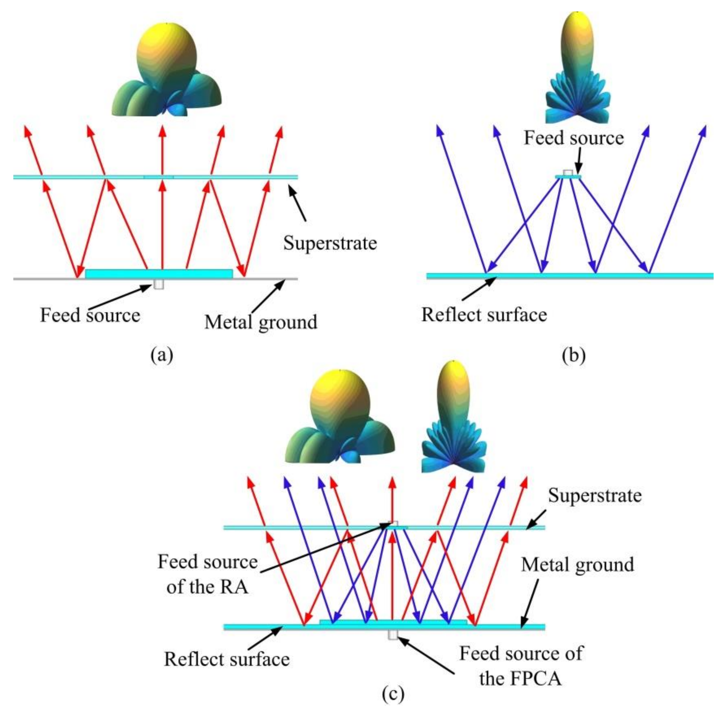
An FPCA usually comprises a feed antenna, a partially reflective superstrate and a metal ground, as shown in Figure 1a. Electromagnetic waves radiated from the feed antenna experience multiple reflections within the cavity. The distance between the superstrate and metal ground is nearly half the wavelength of the working frequency [17,18]. An RA usually comprises a feed antenna and a reflective surface. The reflective surface is illuminated by the feed antenna, and a planar phase surface is formed in front of the aperture, as shown in Figure 1b.

Figure 1.
Working principle of a (a) Fabry-Perot cavity antenna (FPCA), (b)reflectarray antenna (RA), and (c) shared-aperture antenna.
This paper explores the design of an FPCA and an RA that share the same physical aperture, as shown in Figure 1c. The feed source of the RA is located at the center of the substrate of the FPCA, and the reflective surface of the RA is combined with the metal ground of the FPCA. The proposed antenna does not need a power division network, and only a single-layer superstrate is used. The FPCA and RA work independently at S-band (2.45 GHz) and X-band (10 GHz) frequencies, respectively. This study is organized as follows: Section 2 introduces the design principles of the shared-aperture antenna. The simulations and measurements are then presented in Section 3.
2. Shared-Aperture Antenna Design
2.1. FPCA Design
Partially reflective superstrates with a high reflection coefficient should be considered to realize a high gain in FPCAs [19]. The relative gain and resonant cavity height of an FPCA can be calculated as,
where R is the reflection coefficient of the superstrate, D is the relative gain, λ1 is the working wavelength, H is the cavity height, φR and φG represent the reflection phases of the superstrate and ground, respectively. The FPCA designed in this study is intended to work at a frequency of 2.45 GHz. To decrease the complexity of the shared-aperture design, a single-layer uniform superstrate is used. The bandwidth of the FPCA follows,
Figure 2 shows the structure and simulated model of the superstrate unit cell; this structure comprises a 2-mm-thick dielectric substrate and a 0.035-mm-thick metal layer. The unit cell size of the substrate is 20 × 20 mm2, and the dielectric constant of the substrate is 2.65. A square patch with a side length of 18 mm is cut away from the middle square patch with a side length of 16 mm to realize a hollow square ring. Figure 3 shows the magnitude of the simulated reflection coefficient, |S11|, and magnitude of the transmission coefficient, |S21|, of the superstrate unit cell for frequencies from 2 to 12 GHz. The value of |S11| at 2.45 GHz is found to be −0.55 dB. The value of |S21| at 10 GHz is greater than −0.45 dB. The superstrate is almost transparent at 10 GHz.
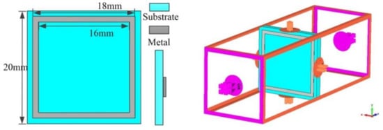
Figure 2.
Structure and simulated model of the superstrate unit cell.

Figure 3.
Simulated |S11| and |S21| of a superstrate unit cell.
The whole superstrate is made up of an array of 15 × 15 units, and the aperture size is 300 × 300 mm2. The simulated values of φR and φG at 2.45 GHz were found to be −152.68° and 180°, respectively. According to Equation (2), the theoretical resonant cavity height, H, is 65.87 mm, which is nearly half the wavelength at a frequency of 2.45 GHz.
2.2. RA Design
RAs often consist of a feed source and a reflective surface. In this study, a rectangular microstrip antenna is used as the feed source. The phase distribution on the reflective surface should satisfy the parabolic distribution [20],
where (x,y) represent the position of the reflective surface unit cell, φ0 is the reflection phase at the reference point, λ2 is the working wavelength of the RA, and H is the focal length. In the design used here, H is also the height of the FPCA.
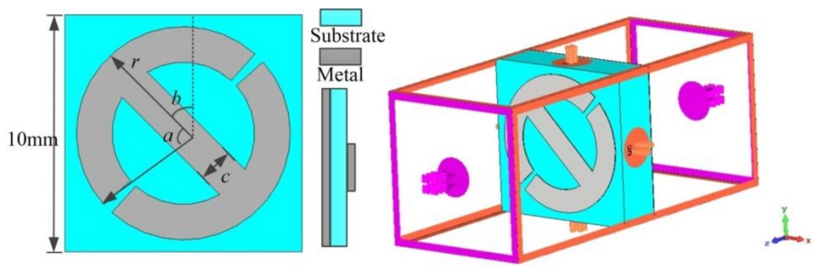
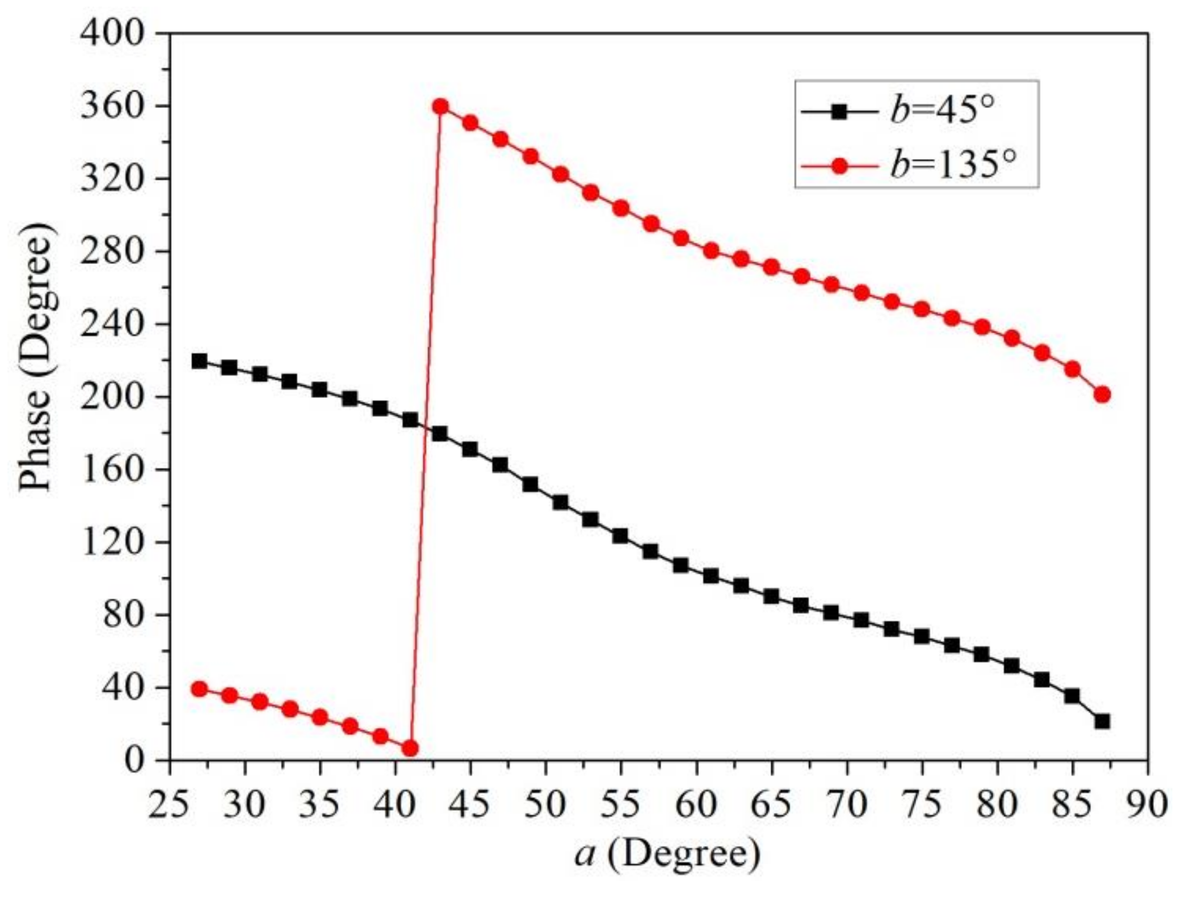
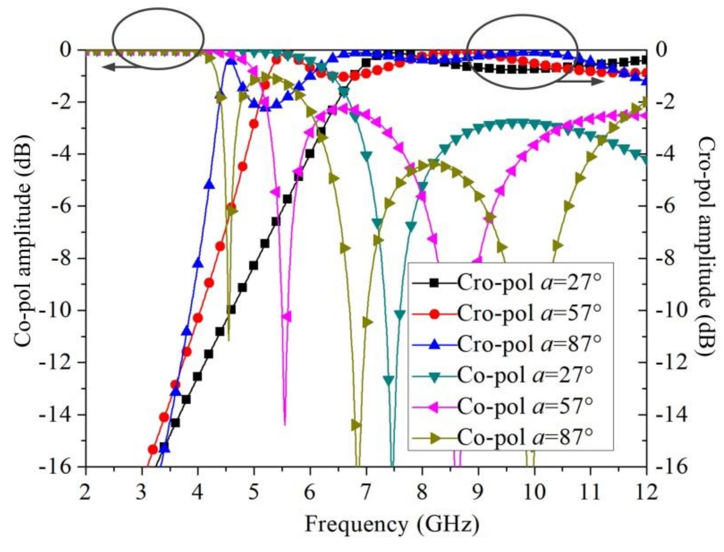
Figure 4 shows the structure and the simulated model of the reflective surface unit cell considered here; this structure comprises a 3-mm-thick dielectric substrate and two metal layers. The unit cell size of the substrate is 10 × 10 mm2, and the dielectric constant of the substrate is 2.65. The two metal layers are on either side of the substrate. One of the metal layers is full metal and the other has a modified I-shape structure [21]. The diameter of the I shape is 9 mm, and its width, c, is 1.5 mm. Figure 5 shows the simulated reflection phase distribution of the reflective surface unit cell at a frequency of 10 GHz. By changing the arc angle, a, and the rotated angle, b, the unit cell can realize the required reflection phase range of 0°–360°. It should be noted that the I shape realizes an orthogonal polarization conversion. When the incident wave is of x-polarization, the main reflected radiation wave is of y-polarization. Figure 6 shows the simulated reflection amplitudes of the reflective surface unit cell with co-polarization and cross-polarization. When the angle a is changed from 27° to 87°, the reflection amplitudes corresponding to radiation of cross-polarization are greater than −0.96 dB at 10 GHz. On the other hand, the reflective surface provides a co-polarization reflection at around 2.45 GHz. The reflection amplitudes of the co-polarization radiation maintain the value of −0.001 dB at 2.45 GHz with the angle a changing.
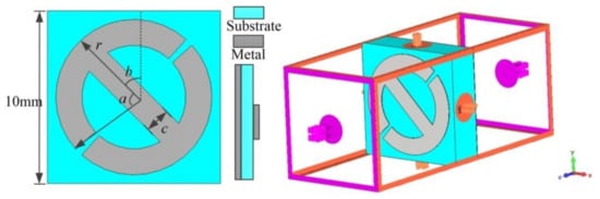
Figure 4.
Structure and simulated model of the reflect surface unit cell.
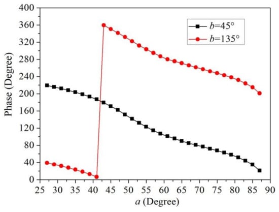
Figure 5.
Simulated 10-GHz reflection phase distributions of a reflect surface unit cell.
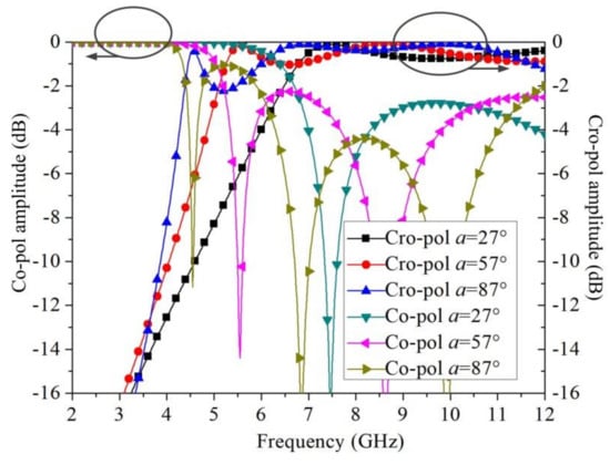
Figure 6.
Simulated reflection amplitudes of a reflect surface unit cell with co-polarization and cross-polarization.
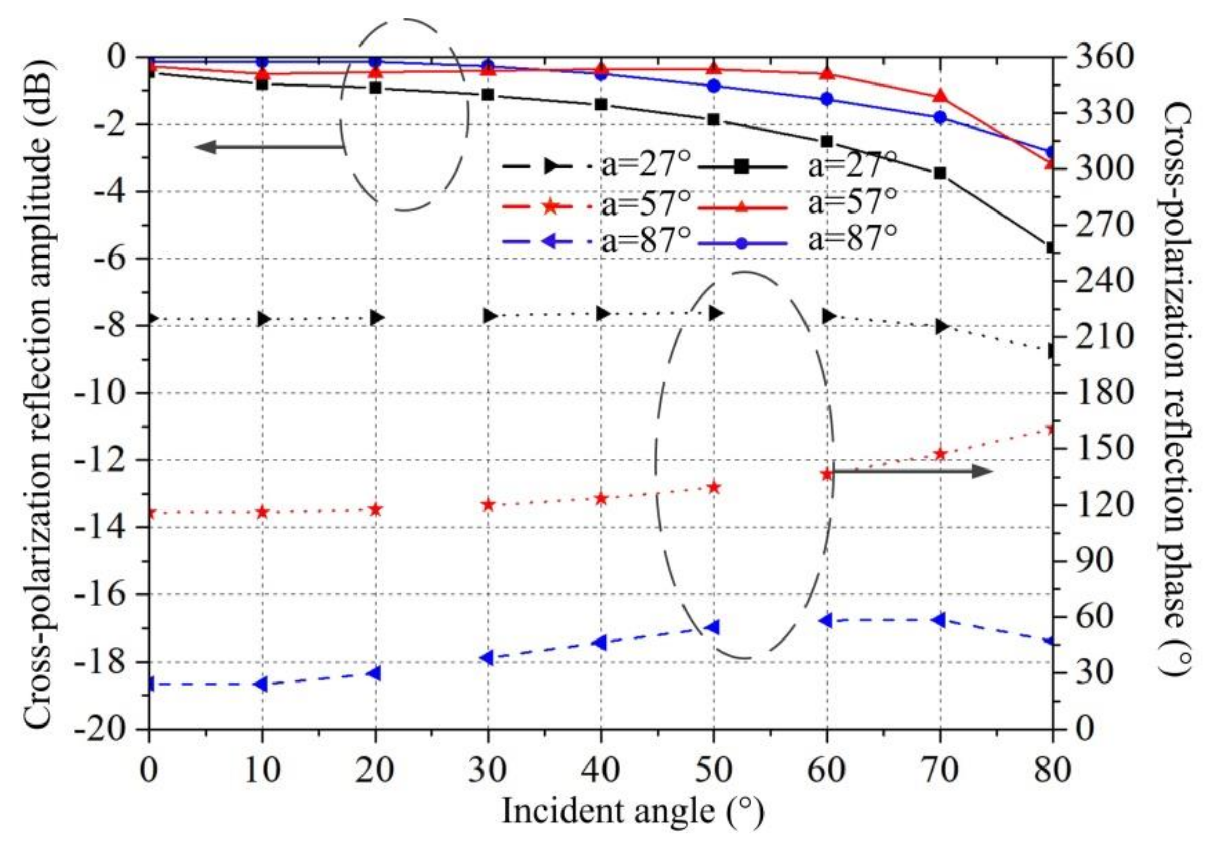
Figure 7 shows the simulated reflection amplitude and phase of a reflect surface unit cell under different incident angles. It is found when the incident angle is less than 60° that the reflection amplitude and phase of the reflective surface unit cell are constant at frequencies of around 10 GHz. The phase difference for b = 45° and b = 135° is independent of the incident angles. The amplitude will decrease when the incident angle is greater than 60°, which may affect the efficiency of the reflectarray. However, in order to realize a high gain (greater than 20 dBi), we retain the use of a reflective surface with a large aperture size.
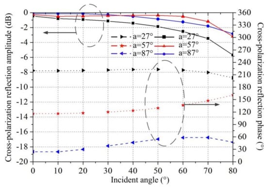
Figure 7.
Simulated cross-polarization reflection amplitude and phase of a reflect surface unit cell under different incident angles.
3. Measurement Results and Discussion
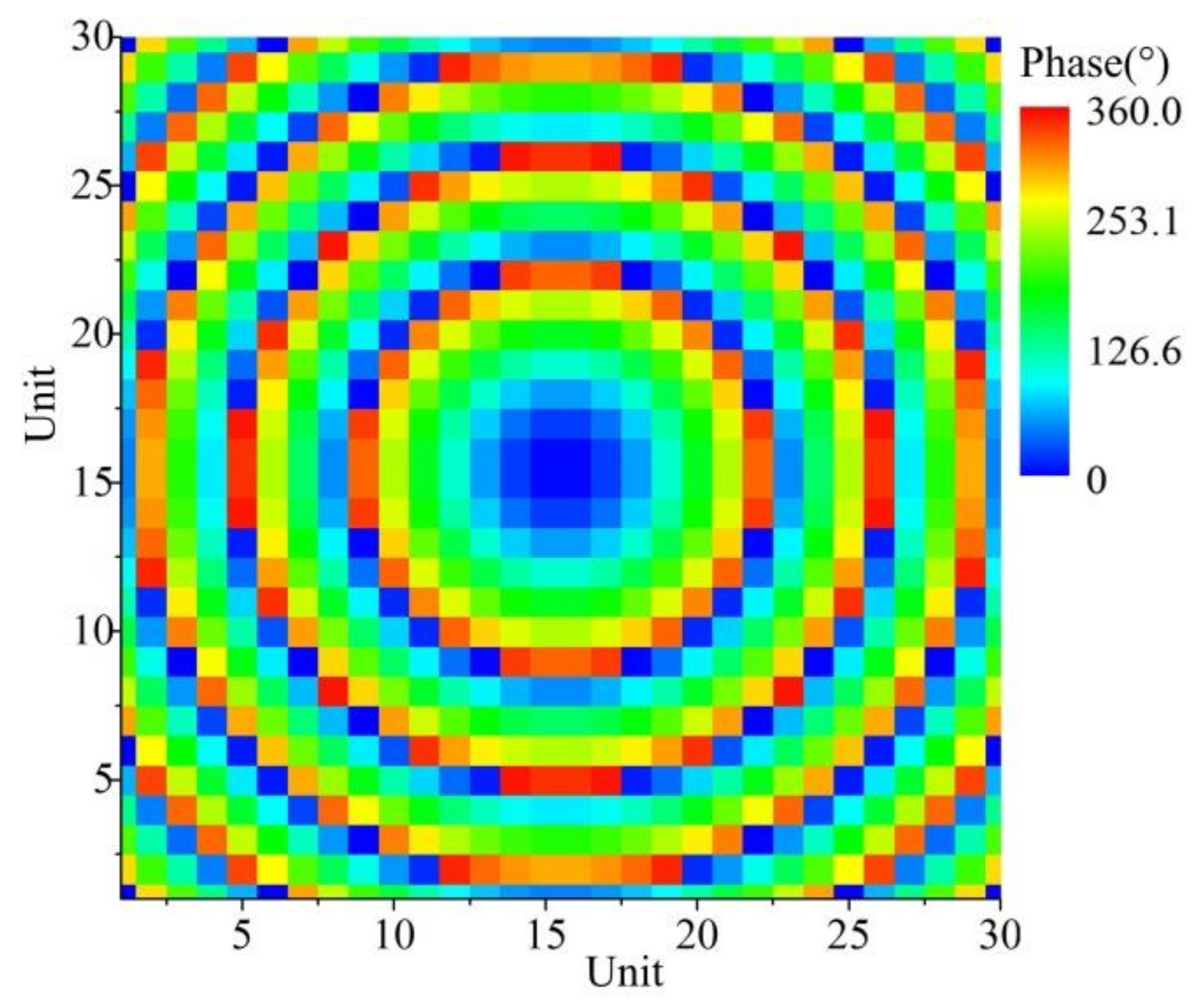
The feed source of the FPCA is a microstrip antenna which is located at the center of the lower layer. After optimizing with the method of genetic algorithm, the resonant cavity height, H, is set to be 65 mm. The feed source of the RA is located at the center of the superstrate of the FPCA, and the phase distribution on the reflective surface can be calculated using Equation (3). Figure 8 shows the obtained phase distribution.
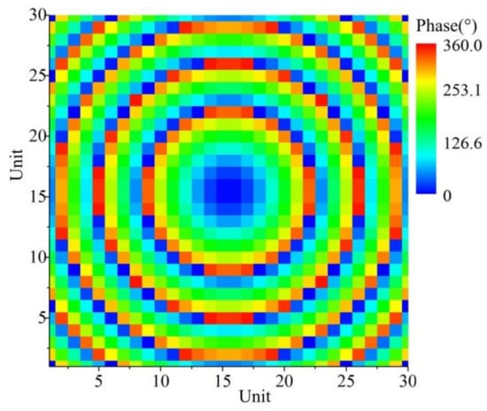
Figure 8.
Phase-shift distribution on the reflectarray surface.
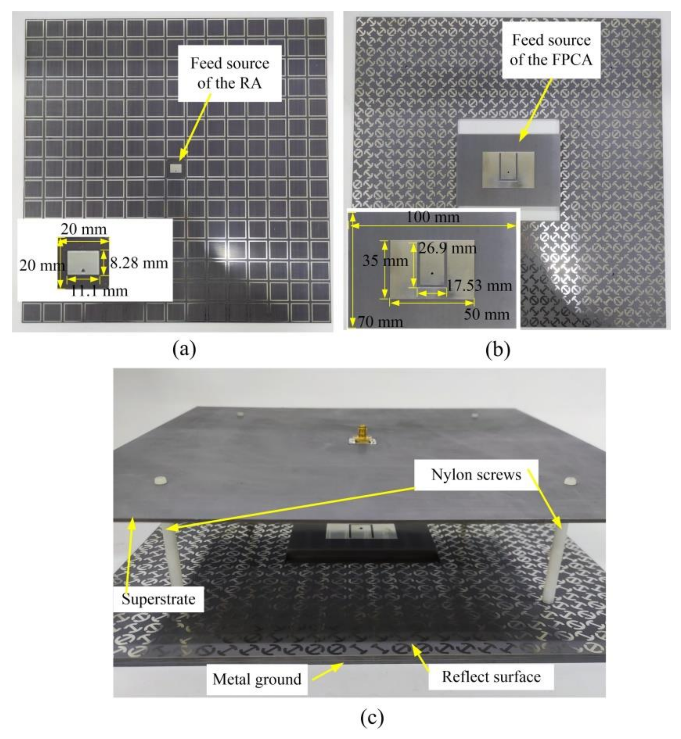
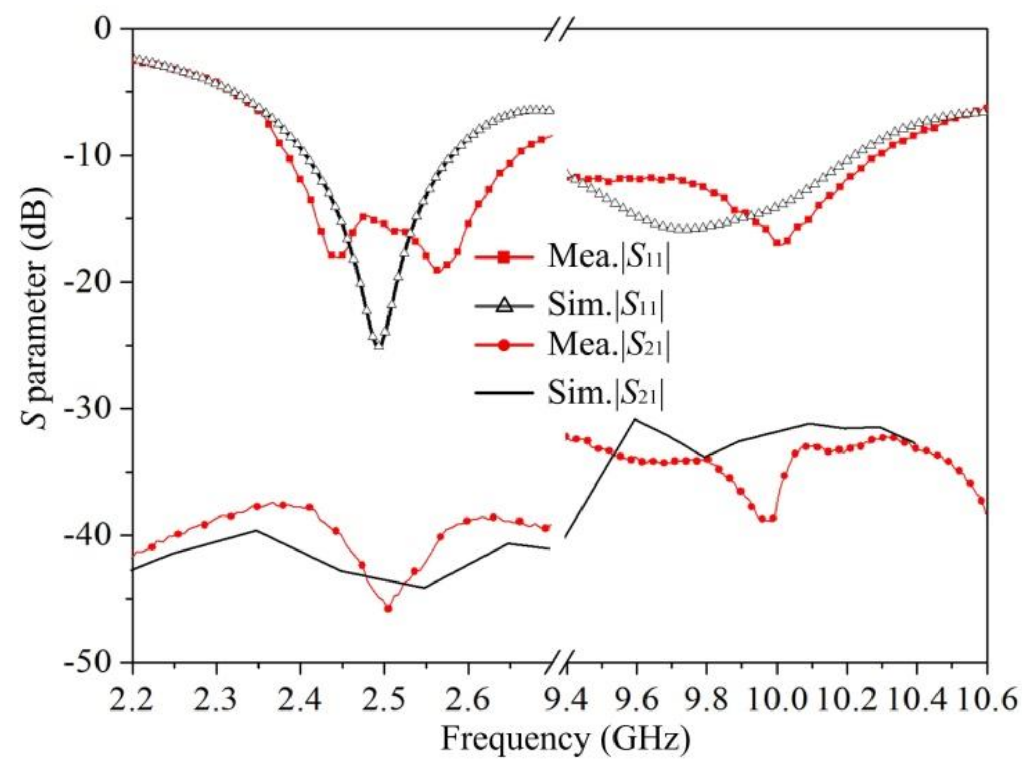
The shared-aperture antenna designed here was then fabricated and measured. The fabricated superstrate, reflective surface, and antenna prototype are shown in Figure 9a–c, respectively. Figure 9a,b also shows the properties of the feed antennas. All of the substrates are made of polytetrafluoroethylene (εr = 2.65, tan δ = 0.001). Nylon screws were used to control the cavity height and fix the whole antenna. The values of |S11| and |S21| for the antenna were then measured using an Agilent E8362B Network Analyzer. As shown in Figure 10, the measured 10-dB return loss bandwidth of the prototype was found to be 10.82% from 2.385 to 2.658 GHz and 8.94% from 9.4 to 10.28 GHz. The value of |S21| in both the frequency bands considered here was lower than −30 dB, which indicates good isolation between the two antenna ports.
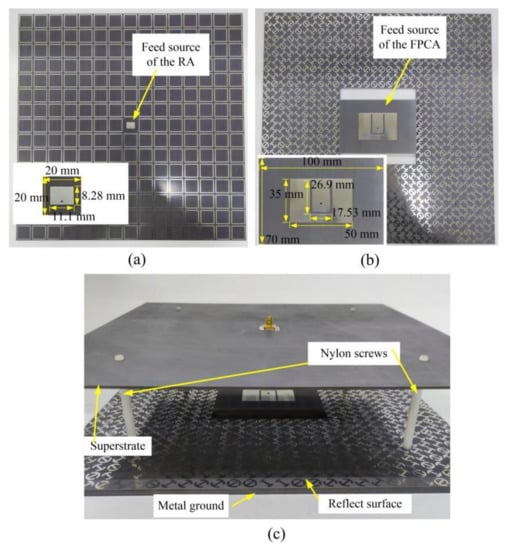
Figure 9.
Photographs of (a) the fabricated superstrate, (b) reflect surface, and (c) antenna prototype.
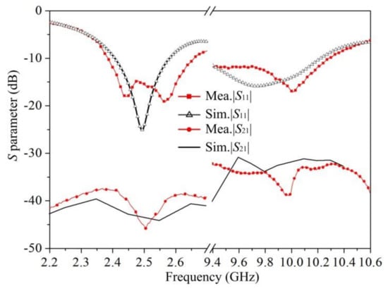
Figure 10.
Simulated and measured S parameters.
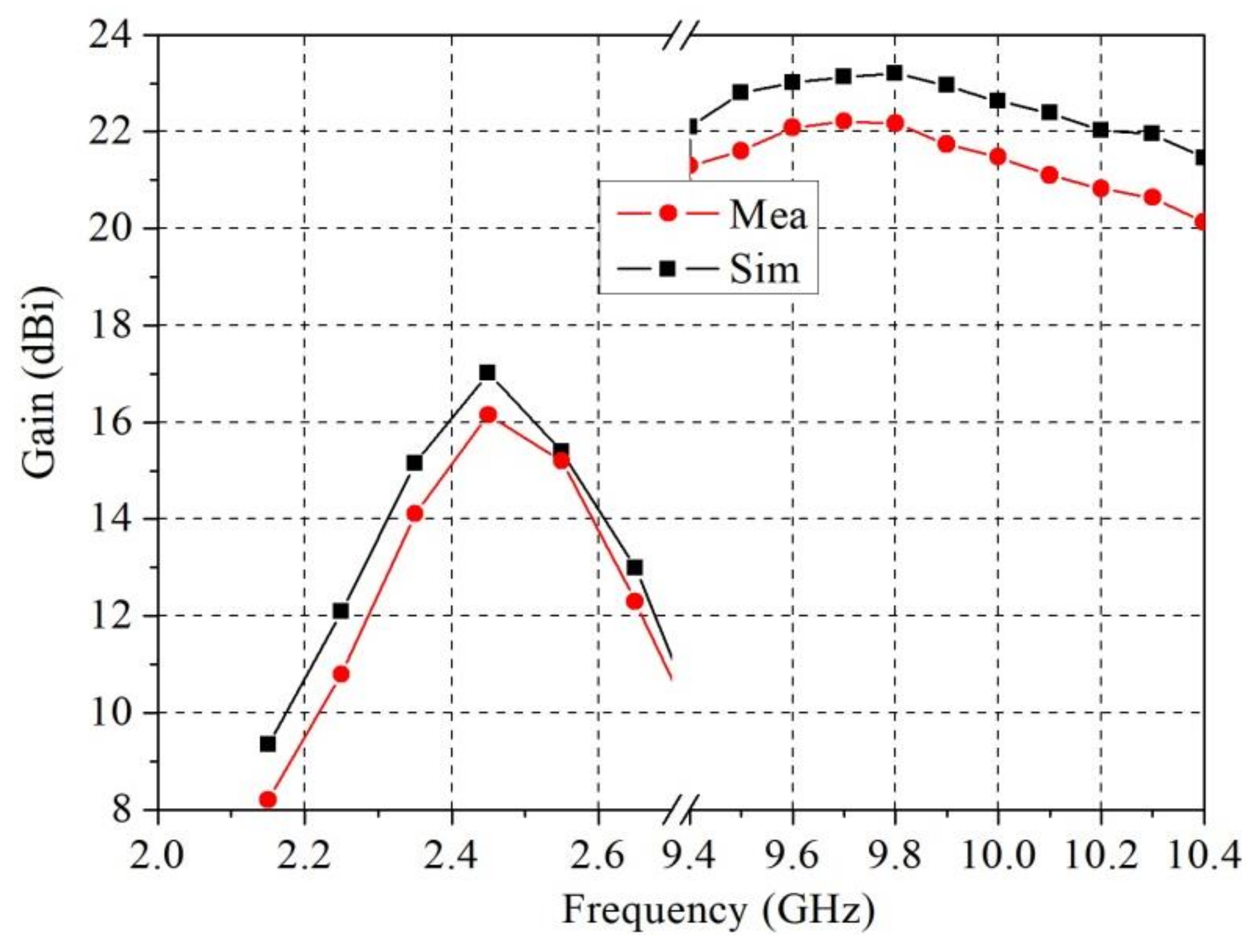
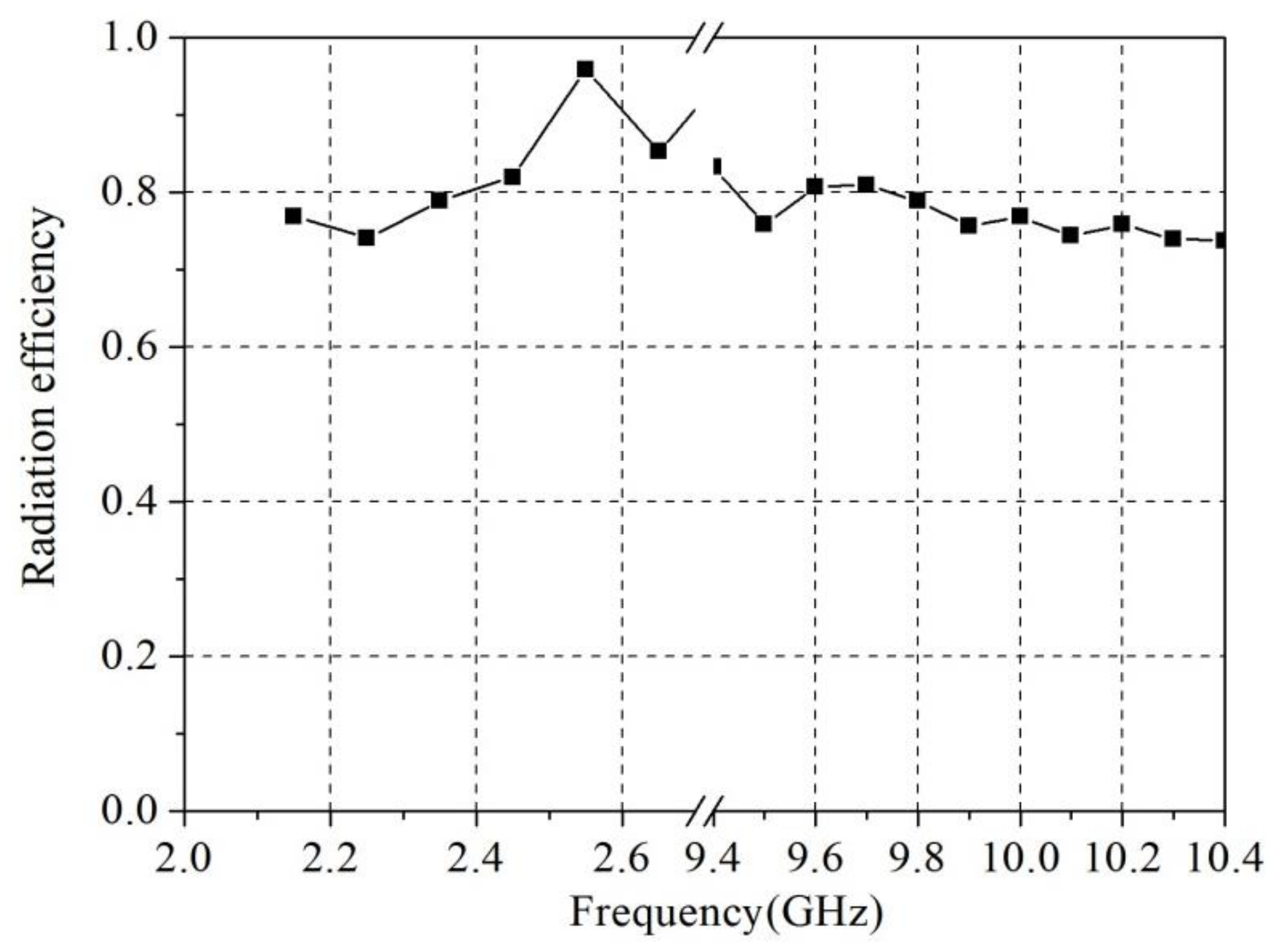
As shown in Figure 11, the simulated gains at frequencies of 2.45 and 10 GHz were found to be 17.01 and 22.62 dBi, respectively. The measured gains were 16.21 dBi at 2.45 GHz and 21.6 dBi at 10 GHz, and the corresponding radiating efficiencies were 83.2% and 79% [22], respectively. The measured gains were lower than those predicted in the simulations; these reduced values may have been caused by fabrication and measurement errors. The aperture efficiencies at 2.45 and 10 GHz were found to be 55.39% and 11.55% [23], respectively. The feed antenna of the FPCA occupied one-ninth of the reflective surface, which influenced the feed illumination of the RA. According to the simulations, the gain at 10 GHz can be increased from 22.62 to 25.21 dBi by removing the feed structure. The RA was found to have a large subtended (half) angle of 72.9°, which leads to a high spillover efficiency but low taper efficiency, and therefore a low aperture efficiency [24]. The deteriorated performance of the reflective surface unit cell under large incident angles, dielectric loss, and center-feed blocking will also decrease the gain of the RA. The 3-dB gain bandwidths of the two frequency bands were found to be 8.16% and 10.1%. The equivalent 1-dB bandwidths were 4.08% and 6.18%, respectively. When the working frequency deviates from 2.45 GHz, the fixed cavity height will no longer match the optimal resonance height, which will result in a decreased gain and thus a narrow gain bandwidth of the FPCA. In contrast, the gains of the RA depend on the feed source and the reflective surface. The feed source and reflective surface can work well at frequencies of around 10 GHz, thus the RA can exhibit relatively stable gains and a wide gain bandwidth. Figure 12 shows the radiation efficiency of the proposed antenna.
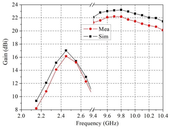
Figure 11.
Simulated and measured gains of the proposed antenna at around 2.45 and 10 GHz.
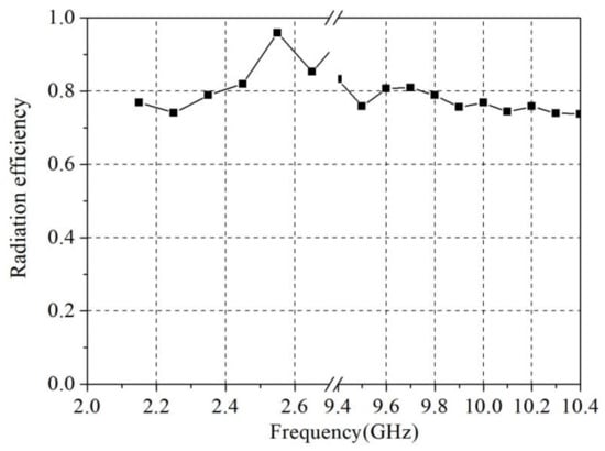
Figure 12.
Radiation efficiency of the proposed antenna.
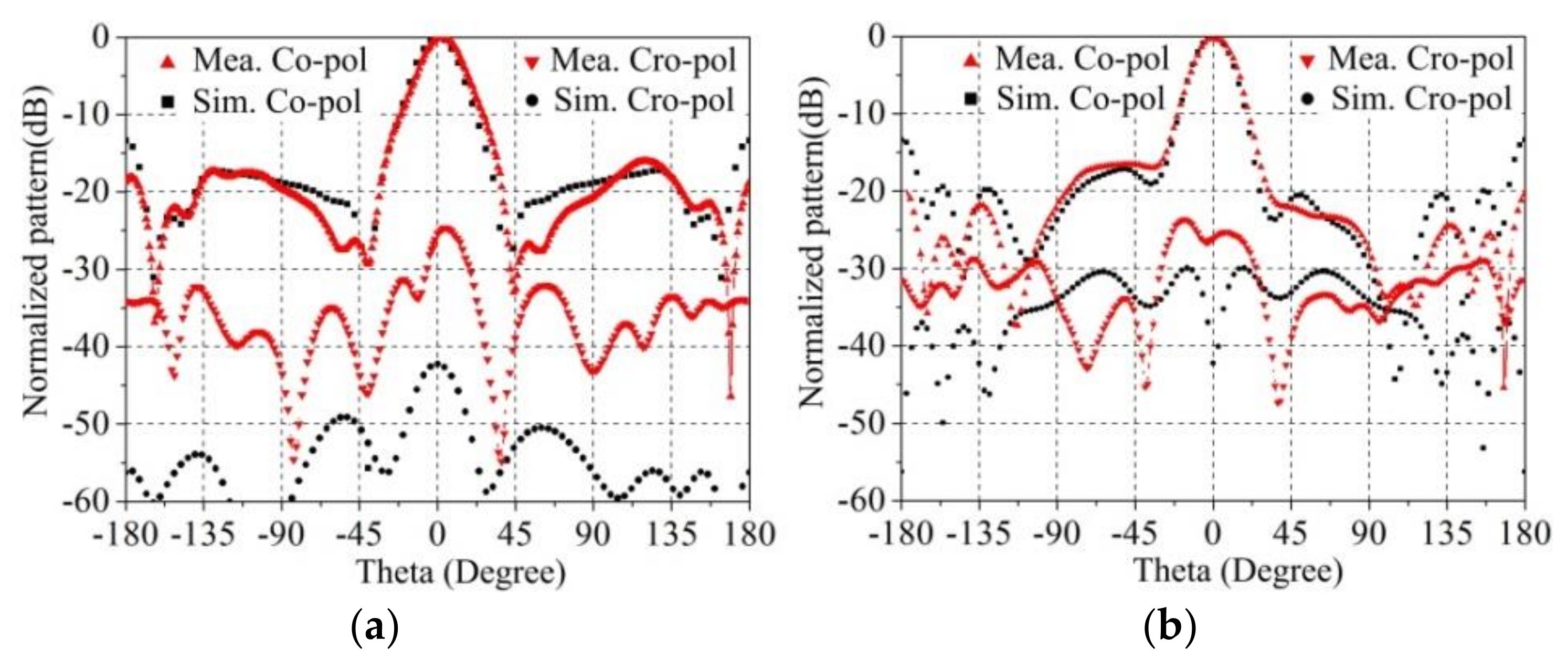
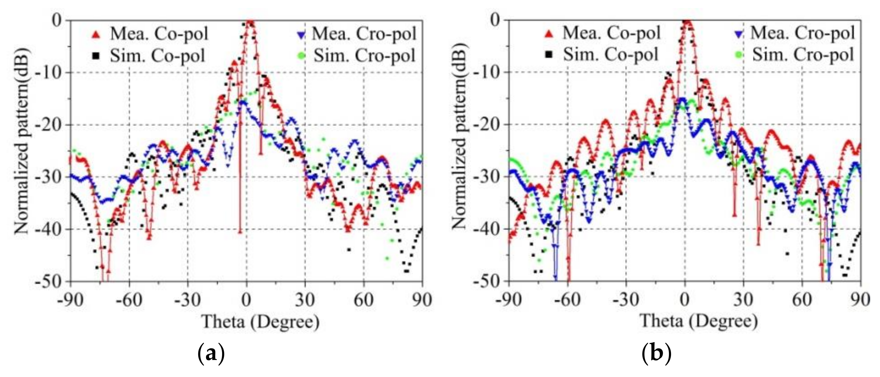
Figure 13 and Figure 14 show the simulated and measured pattern at 2.45 and 10 GHz, respectively. The half-power beamwidth of the E- and H-planes were 22.6° and 21.44° at 2.45 GHz. The beamwidths were 6.31° and 5.46° at 10 GHz. The cross-polarized gains at 2.45 and 10 GHz were 25 dB and 15 dB lower than the co-polarized gains in both planes, respectively. The sidelobe level at 10 GHz was relatively high, which may have also been caused by the feed antenna of the FPCA.
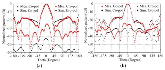
Figure 13.
Simulated and measured radiation patterns (dB) of (a) E plane and (b) H plane at 2.45 GHz.
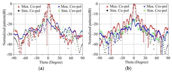
Figure 14.
Simulated and measured radiation patterns (dB) of (a) E plane and (b) H plane at 10 GHz.
Table 1 gives a comparison with some similar works. Compared with [14,16], and [25], our proposed antenna produced high gain in both frequency bands. Although the gain improvement is not high for [13], there is no feeding network in the antenna, and only a single-layer superstrate is used.

Table 1.
Comparison with similar works.
4. Conclusions
In this work, a dual-band high-gain shared-aperture antenna integrating the Fabry-Perot and reflectarray mechanisms was proposed. The design hybridizes an FPCA working at 2.45 GHz and an RA working at 10 GHz. The feed source of the RA is located at the center of the substrate of the FPCA, and the reflective surface of the RA is combined with the metal ground of the FPCA. In this work, a shared-aperture antenna with an aperture size of 300 × 300 mm2 was designed, fabricated, and measured. The proposed antenna was found to have a gain of 16.21 dBi at 2.45 GHz and 21.6 dBi at 10 GHz. The isolation between the two antenna ports was found to be greater than 30 dB. The antenna also has a simple structure with only a single-layer superstrate, which is preferable for practical applications.
Author Contributions
Conceptualization, X.Y. and X.C.; writing—original draft preparation, X.Y., L.Z. and S.H.; writing—review and editing. All authors have read and agreed to the published version of the manuscript.
Funding
This work was supported by Stable-Support Scientific Project of China Research Institute of Radiowave Propagation (Grant No. A132101W09).
Data Availability Statement
Data is contained within the article.
Conflicts of Interest
The authors declare that they have no conflicts of interest.
References
- He, D.; Yu, Q.; Chen, Y.; Yang, S. Dual-band shared-aperture base station antenna array with electromagnetic transparent antenna elements. IEEE Trans. Antennas Propag. 2021, 69, 5596–5606. [Google Scholar] [CrossRef]
- Chen, Y.; Zhao, J.; Yang, S. A novel stacked antenna configuration and its applications in dual-band shared-aperture base station antenna array designs. IEEE Trans. Antennas Propag. 2019, 67, 7234–7241. [Google Scholar] [CrossRef]
- Zhang, J.F.; Cheng, Y.J.; Ding, Y.R.; Bai, C.X. A dual-band shared-aperture antenna with large frequency ratio, high aperture reuse efficiency, and high channel isolation. IEEE Trans. Antennas Propag. 2018, 67, 853–860. [Google Scholar] [CrossRef]
- Mao, C.X.; Gao, S.; Wang, Y.; Chu, Q.X.; Yang, X.X. Dual-band circularly polarized shared-aperture array for C-/X-band satellite communications. IEEE Trans. Antennas Propag. 2017, 65, 5171–5178. [Google Scholar] [CrossRef]
- Zhang, J.; Shen, Z. Dual-band shared-aperture UHF/UWB RFID reader antenna of circular polarization. IEEE Trans. Antennas Propag. 2018, 66, 3886–3893. [Google Scholar] [CrossRef]
- Chen, Y.; Vaughan, R.G. Dual-Polarized L-Band and Single-Polarized X-Band Shared-Aperture SAR Array. IEEE Trans. Antennas Propag. 2018, 66, 3391–3400. [Google Scholar] [CrossRef]
- Mao, C.X.; Gao, S.; Wang, Y.; Luo, Q.; Chu, Q.X. A shared-aperture dual-band dual-polarized filtering-antenna-array with improved frequency response. IEEE Trans. Antennas Propag. 2017, 65, 1836–1844. [Google Scholar] [CrossRef]
- Kwon, G.; Park, J.; Kim, D.; Hwang, K.C. Optimization of a shared-aperture dual-band transmitting/receiving array antenna for radar applications. IEEE Trans. Antennas Propag. 2017, 65, 7038–7051. [Google Scholar] [CrossRef]
- Smith, T.; Gothelf, U.; Kim, O.S.; Breinbjerg, O. An FSS-backed 20/30 GHz circularly polarized reflectarray for a shared aperture L-and Ka-band satellite communication antenna. IEEE Trans. Antennas Propag. 2013, 62, 661–668. [Google Scholar] [CrossRef]
- Liu, Y.; Cheng, Y.J.; Zhao, M.H.; Fan, Y. Dual-band shared-aperture high-efficiency reflectarray antenna based on structure-reuse technique. IEEE Antennas Wirel. Propag. Lett. 2021, 20, 366–370. [Google Scholar] [CrossRef]
- Li, T.; Chen, Z.N. Metasurface-based shared-aperture 5G S-/K-band antenna using characteristic mode analysis. IEEE Trans. Antennas Propag. 2018, 66, 6742–6750. [Google Scholar] [CrossRef]
- Zeb, B.A.; Nikolic, N.; Esselle, K.P. A high-gain dual-band EBG resonator antenna with circular polarization. IEEE Antennas Wirel. Propag. Lett. 2014, 14, 108–111. [Google Scholar] [CrossRef]
- Qin, F.; Gao, S.S.; Luo, Q.; Mao, C.-X.; Gu, C.; Wei, G.; Xu, J.; Li, J.; Wu, C.; Zheng, K.; et al. A simple low-cost shared-aperture dual-band dual-polarized high-gain antenna for synthetic aperture radars. IEEE Trans. Antennas Propag. 2016, 64, 2914–2922. [Google Scholar] [CrossRef]
- Liu, Z.G.; Yin, R.J.; Ying, Z.N.; Lu, W.B.; Tseng, K.C. Dual-band and shared-aperture Fabry–Pérot cavity antenna. IEEE Antennas Wirel. Propag. Lett. 2021, 20, 1686–1690. [Google Scholar]
- Li, T.; Chen, Z.N. Shared-surface dual-band antenna for 5G applications. IEEE Trans. Antennas Propag. 2019, 68, 1128–1133. [Google Scholar] [CrossRef]
- Mei, P.; Zhang, S.; Pedersen, G.F. A dual-polarized and high-gain X-/Ka-band shared-aperture antenna with high aperture reuse efficiency. IEEE Trans. Antennas Propag. 2020, 69, 1334–1344. [Google Scholar] [CrossRef]
- Decoster, B.; Maes, S.; Cuiñas, I.; Sánchez, M.G.; Caldeirinha, R.; Verhaevert, J. Dual-band single-layer fractal frequency selective surface for 5G applications. Electronics 2021, 10, 2880. [Google Scholar] [CrossRef]
- Al-Gburi, A.J.A.; Ibrahim, I.M.; Zakaria, Z.; Abdulhameed, M.K.; Saeidi, T. Enhancing gain for UWB antennas using FSS: A systematic review. Mathematics 2021, 9, 3301. [Google Scholar] [CrossRef]
- Qin, P.Y.; Ji, L.Y.; Chen, S.L.; Guo, Y.J. Dual-polarized wideband Fabry–Pérot antenna with quad-layer partially reflective surface. IEEE Antennas Wirel. Propag. Lett. 2018, 17, 551–554. [Google Scholar] [CrossRef]
- Yu, S.; Liu, H.; Li, L. Design of near-field focused metasurface for high-efficient wireless power transfer with multifocus characteristics. IEEE Trans. Ind. Electron. 2018, 66, 3993–4002. [Google Scholar] [CrossRef]
- Jia, S.L.; Wan, X.; Su, P.; Zhao, Y.J.; Cui, T.J. Broadband metasurface for independent control of reflected amplitude and phase. AIP Adv. 2016, 6, 045024. [Google Scholar] [CrossRef] [Green Version]
- Lai, Q.; Almpanis, G.; Fumeaux, C.; Benedickter, H.; Vahldieck, R. Comparison of the radiation efficiency for the dielectric resonator antenna and the microstrip antenna at Ka band. IEEE Trans. Antennas Propag. 2008, 56, 3589–3592. [Google Scholar]
- Jiang, M.; Hong, W.; Zhang, Y.; Yu, S.; Zhou, H. A folded reflectarray antenna with a planar SIW slot array antenna as the primary source. IEEE Trans. Antennas Propag. 2014, 62, 3575–3583. [Google Scholar] [CrossRef]
- Pozar, D.M.; Targonski, S.D.; Syrigos, H.D. Design of millimeter wave microstrip reflectarrays. IEEE Trans. Antennas Propag. 1997, 45, 287–296. [Google Scholar] [CrossRef]
- Kothapudi, V.K.; Kumar, V. A multi-layer S/X-band shared aperture antenna array for airborne synthetic aperture radar applications. Int. J. RF Microw. Comput. Aided Eng. 2021, 31, e22720. [Google Scholar] [CrossRef]


Publisher’s Note: MDPI stays neutral with regard to jurisdictional claims in published maps and institutional affiliations. |
© 2022 by the authors. Licensee MDPI, Basel, Switzerland. This article is an open access article distributed under the terms and conditions of the Creative Commons Attribution (CC BY) license (https://creativecommons.org/licenses/by/4.0/).