Abstract
This paper presents a planar multi-circular loop antenna with a wide impedance bandwidth for next generation mm-wave systems. The proposed antenna comprises three circular rings with a partial ground plane with a square slot. The resonating structure is designed on a 0.254 mm thin RO5880 substrate with a relative permittivity of 2.3. The single element of the proposed design showed a resonance response from 26.5 to 41 GHz, with a peak gain of 4 dBi and radiation efficiency of 96%. The proposed multicircular ring antenna element is transformed into a four-element array system. The array size is kept at 18.25 × 12.5 × 0.254 mm3 with a peak gain of 11 dBi. The antenna array is fabricated and measured using the in-house facility. The simulated and measured results are well agreed upon and are found to be suitable for mm-wave communication systems.
1. Introduction
With the evolution of communication systems in modern telecommunication infrastructure, 5G is standardized throughout the world, offering high channel capacity characteristics with an increased number of users connected and low latency over the communication channel [,,,]. The 5G spectrum is categorized into two broad regions as Sub6 GHz, ranging under 6 GHz frequency, and mm-wave region, in which frequencies above 24 GHz and above are adopted. The bands of 28 GHz and 37 GHz and 39 GHz are licensed mm-wave bands in the mm-wave spectrum, for which in order to overcome high attenuation and propagation losses, high gain antenna arrays are required [,,,]. These antenna arrays include higher numbers of radiating elements with low-loss feeding networks [,]. There are several antenna systems reported in the literature [,,,,,,]. These antenna systems include substrate integrated waveguide (SIW) antenna systems, air filled gap structures (AFGs), and planar structures. In [], a multilayer antenna array with wideband and high gain characteristics is presented. The frequency range of the reported antenna is 57–71 GHz, with a peak gain of 13.9 dBi and minute sidelobe levels, with the number of Vias included. However, due to the nature of bonding films and asymmetric Vias inside SIW, the reported structure is complex to build and integrate into RF circuits. Waveguide antennas usually accomplish high gain, but the large volume of the metallic waveguide with a high manufacturing price is the main hitch for bulk production. In [], an 8 × 8 element SIW array is presented with a bandwidth range from 35.4–41.7 GHz, total peak radiation efficiency of 82% and realized gain of 26.1 dBi. The array is difficult to assemble due to the higher numbers of Vias included. Planar antenna arrays are simple to assemble compared to SIWs. The transmission line losses are high compared to SIW, but they can be neglected with careful feed network modeling. A four-element T shape planar antenna array is presented in []. The peak gain achieved is 11.5 dBi and the bandwidth attained is 8 GHz, approximately. A modified four-element hook shape antenna array in [] exhibited a dual-beam radiation response, with a small angular beamwidth of twenty-four Degree. A four-element planar antenna in [] shows a dual-band response at the central frequency of 28 GHz and 38 GHz. The reported antenna showed a peak gain of 7 dBi, but the bandwidth at both resonances is extremely low. Metamaterial-induced mm-wave antennas have also been reported, but they are difficult to assemble and the cost and complexity generally increase [,].
In [], a circular shape antenna with a slotted loop structure is presented for Bluetooth and Wi-Fi applications, covering resonance from 2.4 to 3.1 GHz. The antenna is fabricated on an FR4 substrate with a thickness of 1.6 mm. The size of the single element is 35 × 35 mm2. This design is then transformed into a four-element linear array system using the Wilkinson power divider. In the four-element array, the radiating elements are separated at 40 mm apart and the total dimension of the proposed array is 155 × 75 mm2. The peak gain achieved is 8.39, while total efficiency is 77%.
Similarly, Ref. [] presents a single element with a super bandwidth operating from 6.5 to 100 GHz. The proposed antenna offers stable radiation patterns at lower resonance frequencies but at higher frequencies, the radiation patterns deviate. The size of the antenna is 20 × 20 mm2 only while the maximum gain achieved is 10 dB.
Therefore, to address those limitations, in this paper, a three circular novel shape four-element antenna array is presented with dual-beam characteristics. The proposed antenna is simple in structure and provides high gain and dual beam characteristics with a narrow beamwidth. The proposed antenna offers a wide frequency bandwidth of 15.5 GHz and radiation efficiency above 90%. This paper is organized as follows. Section 1 covers the introduction. Section 2 shows the complete design analysis and array transformation. Section 3 shows the results and discussions from the simulated and obtained measured results with a comparison table. In the Section 4, the conclusion of the proposed work is provided.
2. Antenna Design
The proposed multi circular loop ring mm-wave antenna is designed on an ultra-thin Ro5880 substrate, with a relative permittivity of 2.3. The substrate is 0.254 mm in height. Figure 1 shows the proposed antenna’s front and back view. The dimensions of the proposed antenna in mm are as follows: A = 0.3, E = 6.75, M = 9, N = 11.5, DD = 1, O = 4.75. The wide bandwidth characteristic of the proposed antenna is achieved using several numbers of the conducted parametrical studies. These studies included ring interspacing, transmission line feed modeling, and square slot on the ground plane. Figure 2 shows the overall response of the parametrical studies.

Figure 1.
(a) Front (b) back views of the proposed antenna.


Figure 2.
Parametrical studies for (a) slot length (DD), (b) distance among circular loops (c) feedline length (E) and (d) single element.
As observed in Figure 2a, the parameter DD has a significant impact on the resonance response attained. The ground slot parametrical studies were conducted with a 0.1 mm apart value. As shown, at 0.8 mm, the antenna showed resonance from 27 to 42.6 GHz, while for 0.9 mm, the bandwidth ranged from 26.7 to 42.0 GHz. The optimum response was attained at a 1 mm ground slot value, exhibiting bandwidth characteristics from 26 to 41 GHz. It was observed that the ground slot affects higher frequency. In addition, the reflection coefficient response overall moves to lower values. Next, the parametric response concerning the distance between the circular loops is analyzed. The distance impact is analyzed at a 0.1 mm value. As observed in Figure 2b, the lower frequency range is affected by the starting values of 0.65 and 0.7 mm. The optimum response was achieved at 0.75 mm, as after this value, the reflection coefficient response is degraded. Figure 2c shows the feed line modeling effect for the proposed structure. As observed in Figure 2c, at the initial value of 6.55 mm, the resonance response stretches up to 42 GHz but the starting frequency response also moves forward. With the gradual increase of 0.05 mm, the resonance response moved backwards and the optimum response was achieved at 6.75 mm. Figure 2d shows the single element reflection coefficient obtained.
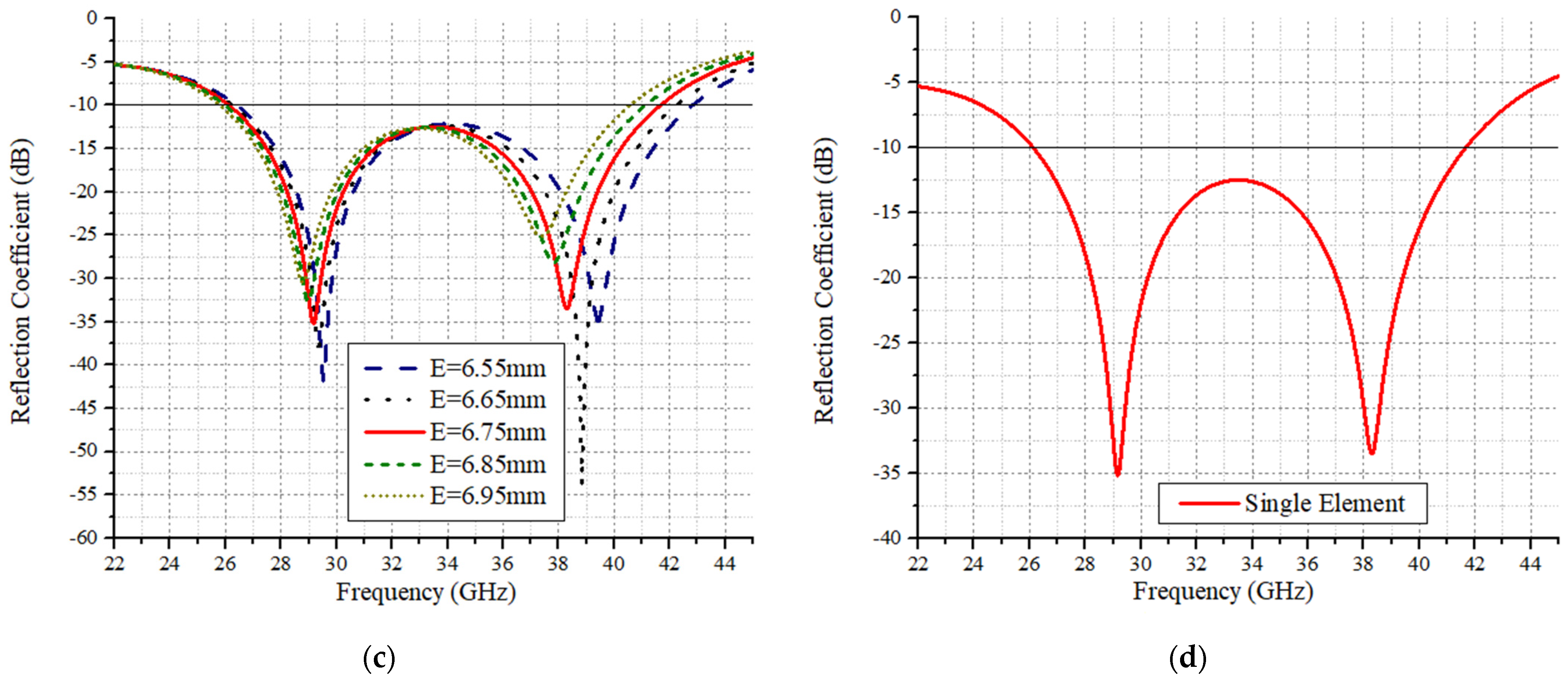
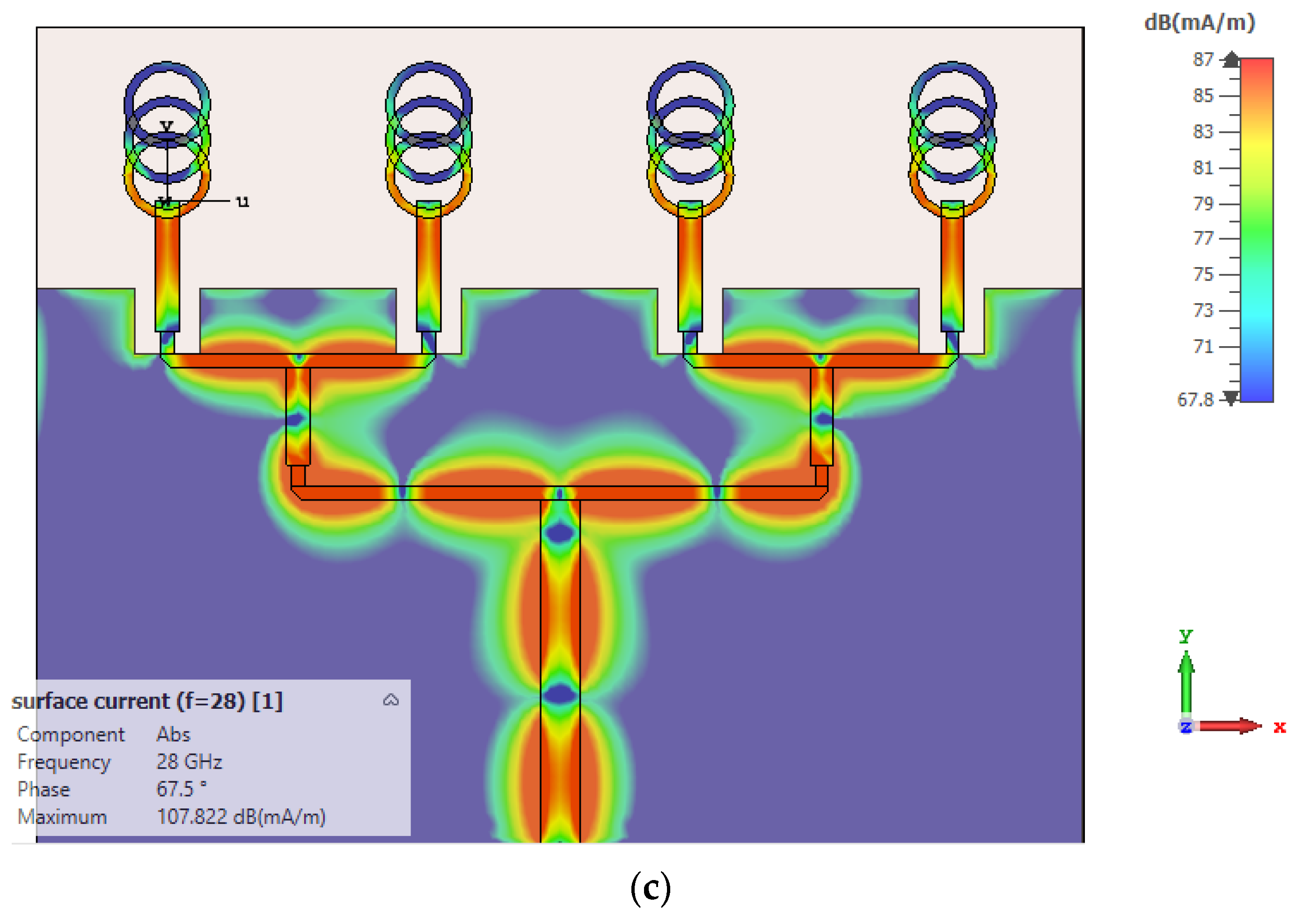
3. Results and Discussions
The proposed multi circular is fabricated and tested using the in-house facility. Figure 3 and Figure 4 show the simulated and measured reflection coefficient and efficiency with the measured gain. As observed in the figure, the reflection coefficient response is in good agreement. The measured gain differs 0.2 dB from the simulated gain at 28 GHz. The simulated radiation and total efficiency are above 95% at 28 GHz.

Figure 3.
Single element simulated and measured reflection coefficient.

Figure 4.
Single element gain and efficiency.
Array Transformation
The proposed design is transformed into a four-element linear array to achieve high gain characteristics. The array is shown in Figure 5. As observed in the figure, the array total length and width are 18.5 × 22.5 mm, respectively. The ground plane length is kept at 12.5 mm. The feed network is composed of a 50 Ω feed line, divided into a 100 Ω feedline, which is further subdivided into 70.7 Ω. The end feedlines connecting each radiating elements are 100 Ω feed lines. The widths of the feedlines are as follows: 50 Ω = 0.7 mm, 100 Ω = 0.28 mm and 70.7 Ω = 0.36 mm. Figure 5c shows the surface current distributions of the feed network at 28 GHz. As observed, the array network distributes power equally among the radiating elements. Figure 6 shows the simulated and measured reflection coefficient response of the proposed four-element array system. From the figure, it is clear that the simulated and measured results are in good agreement. The minute disruptions are the result of fabrication and measurement errors.


Figure 5.
(a) Front layer, (b) back layer, and (c) surface current distributions of the proposed four-element antenna.

Figure 6.
(a) Fabricated prototype (b) simulated and measured S-parameters.
The performance parameters of the proposed antenna array are shown in Figure 7. The radiation efficiency throughout the band of interest is above 89% and the measured efficiency is above 84%. At 28 GHz, the radiation and total efficiency is 94% and 93%, respectively. The gain of the proposed array ranges from 9 dBi to 11.5 dBi. The gain of the antenna array becomes low at the higher frequency end. The simulated gain of the array at 28 GHz is 10.7 dBi and the measured gain is 10.5 dBi. The peak gain achieved is 11.5 dB at 30.5 GHz. Figure 8 shows the proposed antenna array radiation patterns at 28 GHz resonance. The patterns show the far-field characteristics for Phi 90 and Phi = 0. As observed in the figure, the array exhibits a dual-beam characteristic with a very narrow beamwidth, as required for mm-wave systems. The simulated and measured radiation patterns are in good agreement. Figure 9 shows the 3D antenna radiation pattern of the 28 GHz system.

Figure 7.
Performance parameters of array systems.

Figure 8.
Radiation patterns at 28 GHz (a) Phi = 0 (b) Phi = 90.

Figure 9.
3D antenna gain.
Table 1 summarizes the proposed antenna contribution in the literature. The proposed antenna system is compared with Refs. [,,,,,]. Refs. [,,] are based on the planar monopole antenna array, while Refs. [,] are based on the SIW technique. From the table, it is concluded that the proposed antenna array is well designed and delivers high gain with reduced size and wide bandwidth characteristics.

Table 1.
Proposed four-element array comparison with the published literature.
4. Conclusions
This paper presented a novel circular ring shape antenna on a thin RO5880 substrate. The antenna exhibited a wideband response from 26.5 to 41 GHz, with gain varying between 3 and 5.4 dBi and radiation efficiency greater than 90% throughout the bandwidth. The proposed antenna was transformed into a four-element linear array system. The size of the array was 18.5 × 12.5, which is quite small, and the bandwidth of the array was observed to be from 26 to 38.5 GHz. The peak gain achieved was 11.5 dBi, while at 28 GHz, it was observed to be 10.7 dBi. The proposed four-element array is fabricated, and the simulated and measured results were found to be in good agreement. Through the performance comparison with the reported literature, the proposed antenna system was found to be a potential candidate for next generation mm-wave communication systems.
Author Contributions
Conceptualization, R.A.A.-A., M.E.M. and S.H.K.; methodology, J.I., M.A.K. and A.G.A.H.; software, M.E.M. and S.H.K.; validation, C.H.S., M.A.K. and A.G.A.H.; formal analysis, N.O.P.; investigation, J.I. and N.O.P.; resources, M.M. and H.M.; data curation, M.M. and H.M.; writing—original draft preparation, M.E.M. and S.H.K.; writing—review and editing, J.I., N.O.P., C.H.S. and S.H.K.; visualization, J.K.; supervision, M.M. and J.K.; project administration, S.H.K.; funding acquisition, M.M., R.A.A.-A. and C.H.S. All authors have read and agreed to the published version of the manuscript.
Funding
Princess Nourah bint Abdulrahman University Researchers Supporting Project number (PNURSP2022R137), Princess Nourah bint Abdulrahman University, Riyadh, Saudi Arabia. The work of Mohamed Marey is supported by Prince Sultan University.
Institutional Review Board Statement
Not applicable.
Informed Consent Statement
Not applicable.
Data Availability Statement
All data have been included in the study.
Acknowledgments
Princess Nourah bint Abdulrahman University Researchers Supporting Project number (PNURSP2022R137), Princess Nourah bint Abdulrahman University, Riyadh, Saudi Arabia. The work of Mohamed Marey is supported by Prince Sultan University.
Conflicts of Interest
The authors declare no conflict of interest.
References
- Ahmad, A.; Choi, D.-Y.; Ullah, S. A compact two elements MIMO antenna for 5G communication. Sci. Rep. 2022, 12, 3608. [Google Scholar] [CrossRef] [PubMed]
- Farooq, U.; Rather, G. A miniaturised Ka/V dual band millimeter wave antenna for 5G body centric network applications. Alex. Eng. J. 2022, 61, 8089–8096. [Google Scholar] [CrossRef]
- Bilal, M.; Naqvi, S.I.; Hussain, N.; Amin, Y.; Kim, N. High-Isolation MIMO Antenna for 5G Millimeter-Wave Communication Systems. Electronics 2022, 11, 962. [Google Scholar] [CrossRef]
- Luo, Y.; Shen, Y.; Cai, X.; Qian, F.; Xu, S.; Cui, H.; Yang, G. Substrate integrated coaxial line design for mmWave antenna with multilayer configuration. Int. J. RF Microw. Comput. Eng. 2022, 32, e23090. [Google Scholar] [CrossRef]
- Kim, G.; Kim, S. Design and Analysis of Dual Polarized Broadband Microstrip Patch Antenna for 5G mmWave Antenna Module on FR4 Substrate. IEEE Access 2021, 9, 64306–64316. [Google Scholar] [CrossRef]
- Attiah, M.L.; Isa, A.A.M.; Zakaria, Z.; Abdulhameed, M.K.; Mohsen, M.K.; Ali, I. A survey of mmWave user association mechanisms and spectrum sharing approaches: An overview, open issues and challenges, future research trends. Wirel. Netw. 2019, 26, 2487–2514. [Google Scholar] [CrossRef]
- Askari, H.; Hussain, N.; Sufian, A.; Lee, S.M.; Kim, N. A Wideband Circularly Polarized Magnetoelectric Dipole Antenna for 5G Millimeter-Wave Communications. Sensors 2022, 22, 2338. [Google Scholar] [CrossRef] [PubMed]
- Kiani, S.H.; Alharbi, A.G.; Khan, S.; Marey, M.; Mostafa, H.; Khan, M.A. Wideband Three Loop Element Antenna Array for Future 5G mmwave Devices. IEEE Access 2022, 10, 22472–22479. [Google Scholar] [CrossRef]
- Park, S.-J.; Shin, D.-H. Low Side-Lobe Substrate-Integrated-Waveguide Antenna Array Using Broadband Unequal Feeding Network for Millimeter-Wave Handset Device. IEEE Trans. Antennas Propag. 2016, 64, 923–932. [Google Scholar] [CrossRef]
- Li, X.; Xiao, J.; Qi, Z.; Zhu, H. Broadband and High-Gain SIW-Fed Antenna Array for 5G Applications. IEEE Access 2018, 6, 56282–56289. [Google Scholar] [CrossRef]
- Kiani, S.H.; Ren, X.C.; Bashir, A.; Rafiq, A.; Anjum, M.R.; Kamal, M.M.; Din, B.U.; Muhammad, F. Square-Framed T Shape mmwave Antenna Array at 28 GHz for Future 5G Devices. Int. J. Antennas Propag. 2021, 2021, 2286011. [Google Scholar] [CrossRef]
- Kamal, M.; Yang, S.; Kiani, S.; Sehrai, D.; Alibakhshikenari, M.; Abdullah, M.; Falcone, F.; Limiti, E.; Munir, M. A Novel Hook-Shaped Antenna Operating at 28 GHz for Future 5G mmwave Applications. Electronics 2021, 10, 673. [Google Scholar] [CrossRef]
- Raheel, K.; Altaf, A.; Waheed, A.; Kiani, S.; Sehrai, D.; Tubbal, F.; Raad, R. E-Shaped H-Slotted Dual Band mmWave Antenna for 5G Technology. Electronics 2021, 10, 1019. [Google Scholar] [CrossRef]
- Tariq, S.; Naqvi, S.I.; Hussain, N.; Amin, Y. A Metasurface-Based MIMO Antenna for 5G Millimeter-Wave Applications. IEEE Access 2021, 9, 51805–51817. [Google Scholar] [CrossRef]
- Jeong, M.; Hussain, N.; Abbas, A.; Rhee, S.Y.; Lee, S.M.; Gil, S.; Kim, N. Performance improvement of microstrip patch antenna using a novel double-layer concentric rings metaplate for 5G millimeter wave applications. Int. J. RF Microw. Comput. Eng. 2020, 31, e22509. [Google Scholar] [CrossRef]
- Zhou, W.; Arslan, T. A bidirectional planar monopole antenna array for WiFi/Bluetooth and LTE mobile applications. In Proceedings of the 2013 Loughborough Antennas & Propagation Conference (LAPC), Loughborough, UK, 11–12 November 2013; pp. 190–193. [Google Scholar] [CrossRef]
- Chu, S.; Hasan, N.; Yan, J.; Chu, C.C. A Planar Super Wideband Annular Ring Monopole Antenna with Time Domain Characterization. In Proceedings of the 2018 Asia-Pacific Microwave Conference (APMC), Kyoto, Japan, 6–9 November 2018. [Google Scholar] [CrossRef]
- Ullah, H.; Tahir, F.A. A broadband wire hexagon antenna array for future 5G communications in 28 GHz band. Microw. Opt. Technol. Lett. 2019, 61, 696–701. [Google Scholar] [CrossRef]
- Ullah, H.; Tahir, F.A. A High Gain and Wideband Narrow-Beam Antenna for 5G Millimeter-Wave Applications. IEEE Access 2020, 8, 29430–29434. [Google Scholar] [CrossRef]
Publisher’s Note: MDPI stays neutral with regard to jurisdictional claims in published maps and institutional affiliations. |
© 2022 by the authors. Licensee MDPI, Basel, Switzerland. This article is an open access article distributed under the terms and conditions of the Creative Commons Attribution (CC BY) license (https://creativecommons.org/licenses/by/4.0/).