Abstract
Over the past two decades, Long Short-Term Memory (LSTM) networks have been used to solve problems that require modeling of long sequence because they can selectively remember certain patterns over a long period, thus outperforming traditional feed-forward neural networks and Recurrent Neural Network (RNN) on learning long-term dependencies. However, LSTM is characterized by feedback dependence, which limits the high parallelism of general-purpose processors such as CPU and GPU. Besides, in terms of the energy efficiency of data center applications, the high consumption of GPU and CPU computing cannot be ignored. To deal with the above problems, Field Programmable Gate Array (FPGA) is becoming an ideal alternative. FPGA has the characteristics of low power consumption and low latency, which are helpful for the acceleration and optimization of LSTM and other RNNs. This paper proposes an implementation scheme of the LSTM network acceleration engine based on FPGA and further optimizes the implementation through fixed-point arithmetic, systolic array and lookup table for nonlinear function. On this basis, for easy deployment and application, we integrate the proposed acceleration engine into Caffe, one of the most popular deep learning frameworks. Experimental results show that, compared with CPU and GPU, the FPGA-based acceleration engine can achieve performance improvement of 8.8 and 2.2 times and energy efficiency improvement of 16.9 and 9.6 times, respectively, within Caffe framework.
1. Introduction
As one of the most difficult problems in data science, sequence prediction, such as speech recognition [1] and language understanding [2], has been around for a long time. In recent years, with the technical breakthrough of data science, especially deep learning networks, the LSTM network [3] has gradually become an effective solution that can solve almost all sequence problems. LSTMs are widely used in many sequence modeling tasks, including many natural language processing tasks.
Similar to other deep learning networks, the model size of the LSTM network is constantly increasing to improve its accuracy. However, larger models lead to more computations, and the general CPU gets overwhelmed with a big amount of computations. Therefore, some recent work has begun to explore devices that excel at parallel computing, such as GPUs [4], to accelerate the LSTM. However, in addition to the high power consumption of GPU, the inherent recurrent characteristics of LSTM also become the main bottleneck of parallel processing on GPU.
Due to FPGA’s low energy consumption, low latency, high performance and reconfigurability, it has attracted more and more attention in the field of LSTM network acceleration. Although the above characteristics can guarantee the FPGA has a very good balance in processing performance and energy consumption, FPGA development requires specialized knowledge and experience of software and hardware, and it often takes months to optimize a complicated computing task, so this difficult development process may be unacceptable for general machine learning researchers. It is also because of the complexity of FPGA development that frameworks are limited to provide only CPU or GPU support, but lack FPGA support, while LSTM has been implemented in many popular deep learning frameworks [5,6,7,8]. We notice that, to accelerate LSTM networks on an FPGA, programmers can run LSTM networks by simply defining them in a configuration file if they can be deployed using existing learning frameworks. If not, programmers need to manually design the LSTM network for each different model, verify its correctness and then optimize its performance.
To overcome the challenges of computing and energy efficiency, we propose an FPGA-based LSTM acceleration engine and integrate it into the Caffe framework [8] to make the LSTM network easier to deploy. The LSTM acceleration engine in this paper can also be easily integrated into other deep learning frameworks, such as Tensorflow [7].
The contributions of this paper are as follows:
(1) We implement the LSTM acceleration engine based on FPGA and integrate it into the Caffe framework to form a general LSTM acceleration framework for the cooperative work of CPU and FPGA. Using the trained model, LSTM inference can be run directly in the Caffe framework without complicated modification, and the LSTM network can be accelerated on FPGA.
(2) In the LSTM acceleration engine, we apply the systolic array algorithm to the FPGA to implement matrix multiplication. To make the algorithm more practical, we use the matrix blocking method, so that the computation of large matrix multiplication can be executed on the FPGA with limited resources.
(3) The special 12-bit fixed-point format is deployed in the computation instead of the general 32-bit floating-point format, which greatly reduces the number of clock cycles and resource consumption of basic addition and multiplication operations without affecting the accuracy of the results. On this basis, a lookup table method is used to fit the nonlinear activation function to achieve fast and accurate computation.
(4) Aiming at the possible decrease of prediction accuracy caused by optimization work, we develop a simple index to judge whether the optimization work is acceptable.
This paper is organized as follows. Section 2 reviews related work. Section 3 introduces the background information of LSTM. Section 4 describes the implementation and optimization of LSTM on FPGA in detail. Section 5 introduces the integration of LSTM acceleration engine and Caffe framework. Section 6 shows the experimental results, which are mainly represented with resource utilization and performance. Section 7 discusses how to develop acceptability index. Section 8 concludes the paper.
2. Related Work
In recent years, FPGA has become one of the popular platforms to implement DNN acceleration due to its low power consumption, low latency, high performance and reconfigurability. Much FPGA-based work focuses on Convolutional Neural Network (CNN) acceleration to meet the challenges of computing resources and energy consumption on CNN. The authors of [9,10,11,12] proposed to accelerate CNN on FPGA using simplified numerical precision to save chip resource consumption. The authors of [13,14] proposed CNN architecture implemented in FPGA with the Winograd algorithm to reduce the complexity of convolution operation and accelerate the computation process. Bai et al. [15] specifically used depthwise separable convolution to implement the CNN accelerator. Yu et al. [16] specifically studied the implementation of lightweight CNN in FPGA. Ma et al. [17] described a performance model to evaluate the performance and resource utilization of CNN inference implemented in FPGA. The authors of [18,19] proposed hardware-oriented algorithms for computing convolutions.
Research on RNN, especially on LSTM, are rare in comparison with CNNs. Referring to [20], LSTM is implemented in hardware using Xilinx’ FPGA Zynq7020. Its LSTM implementation is limited by Zynq’s resources. The network has only two layers and 128 hidden units, which is not practical for deployment. According to [21], sparse LSTM is proposed for practical speech recognition. It uses prune-based compression to reduce the size of the model to accommodate the FPGA’s limited space, and then a scheduler assists the parallel operations on the FPGA. Similarly, Wang et al. [22] adopted structured compression technology, and the FFT algorithm was used to accelerate the LSTM inference process. As is known, the sparse pruning model is very “irregular” in terms of computational characteristics, which have negative effects on data access and large-scale parallel computing in computing devices, thus affecting the overall efficiency. Considering how to achieve high model accuracy and high hardware execution efficiency simultaneously in a sparse neural network, Cao et al. [23] proposed the bank-balanced sparsity.
To overcome the contradiction between computation and efficiency caused by sparsity, we make use of the characteristic of fast matrix multiplication in the systolic array and remove the resource constraints on FPGA by matrix blocking, thus effectively solving the large matrix multiplication problem in LSTM. In addition, the implementation of LSTM on FPGA is further optimized by using fixed-point number operation and activation function based on lookup table, which improves resource utilization and latency performance. These methods are orthogonal to other LSTM implementations mentioned above and can be easily applied to existing FPGAs.
3. LSTM
As a special kind of recurrent neural network, LSTM is more effective than the standard RNN on solving sequence-related problems. In the process of network propagation, it can selectively remember important features and discard some relatively unimportant features for a long time. The structure of the LSTM cell is shown in Figure 1. The LSTM cell corresponding to the current time step t accepts an input sequence from the current time step and a sequence from the previous step as input and generates output as part of the input for the next time step. This feedback continues on the network until the specified time step T is reached. Each LSTM cell contains a special memory to store the current network state . Besides, it contains an input gate, a cell gate, an output gate and a forget gate to support storing and discarding features.
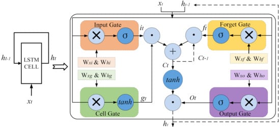
Figure 1.
The structure of the LSTM neural cell.
Formulas (1)–(6) describe the operation of four gates—input gate, forget gate, output gate and cell gate—and the computation method of gate output for each time step, as well as the generation method of state and output .
where i, f, o, g, c and h are, respectively, input gate, forget gate, output gate, cell gate, cell state and cell output, and their widths are the same. The subscript t denotes the current time step and denotes the previous time step. The + operator denotes element-wise addition and the ⊙ operator denotes element-wise multiplication. denotes the weight matrix (e.g., is the weight matrix from the input vector to the input gate) and denotes the bias vector. If the size of the input vector is I, the size of the bias vector b and the size of the output vector are both N, and then the sizes of the weight matrices and are N×I and N×N, respectively.
4. Implementation and Optimization of LSTM
The LTSM acceleration engine proposed in this paper is implemented in a modular way. Its three-stage system structure is shown in Figure 2. The computation of LSTM consists of three stages, each of which corresponds to a hardware module. The first stage is the matrix multiplication module. The input data , and weight matrix W are read, and the matrix multiplication is completed by using the systolic array algorithm. Its output is stored in global memory on the chip as a temporary result. In the second stage, the activation function module reads the input data from the temporary result buffer, calculates the activation function by looking up the table and obtains the output vectors of i, f, o and g, as shown in Formulas (1)–(4). The lookup table is pre-set in the RAM, which is equivalent to fast computation. The output of each gate is also buffered and stored in global memory on the chip. The third stage is the element-wise computation module, which reads the data of i, f, o and g from the buffer; completes the element-wise computation, as shown in Formulas (5) and (6); obtains the output and cell state ; and sends them to the next time step as its input. After completing all the required time steps, the final output is written back to host memory.

Figure 2.
The system structure of the proposed LSTM accelerator.
The implementation and optimization of each module in Figure 2 are described in detail in the following subsections.
4.1. Matrix Multiplication
According to Formulas (1)–(4), the computation of the four gates of the LSTM layer involves eight pairs of matrix–vector multiplication: x, x, x, x, h, h, h and h. The transposing substitution in Formulas (1)–(4) allows matrix multiplication to be replaced by . In other words, x and h can be combined into an input vector of size K and , and and are combined into a weight matrix of size K×N. Assuming that the batch size is M, the operation becomes a matrix multiplication, that is, processing M input vectors at one time, with the input matrix size M×K and the weight matrix size K×N. Matrix multiplication is the most time-consuming part of the whole system, and the systolic array algorithm is deployed to accelerate the computation.
4.1.1. Matrix Partitioning and Rearrangement
Matrix multiplication in neural networks can often be accelerated by parallel processing. However, in the case of large weight matrix and limited computing resources, it means that all computations cannot be completed at one time. To use the systolic matrix for parallel acceleration, the input matrix and the weight matrix need to be pre-divided into small blocks. Figure 3 shows how the matrix is partitioned and rearranged. In the figure, it is assumed that the size of the input matrix and the weight matrix are M×K and K×N, respectively, and the size of the multiplied output matrix is M×N. The input matrix is divided into m×k small blocks, the weight matrix is divided into k×n small blocks and the output matrix results in m×n small blocks, where , , and is the one-dimensional size of the systolic matrix. To ensure that the rows and columns of the matrix are divisible by , some additional zeros are added into the input matrix as padding if needed. In the synthesis process of the Vivado HLS, the development tool of Xilinx FPGA, the weight matrix consuming a lot of resources will be stored in the BRAM as global memory. When used for computations, weight data are read from global memory into the cell’s local memory (LUTRAM). If all data are read in column order, there will be data discontinuity, seriously affecting the efficiency of data reading. Therefore, it is necessary to rearrange the elements in the matrix, as shown at the bottom of Figure 3; the matrix blocks in the matrix are arranged in the same order as the reading order in the computation.
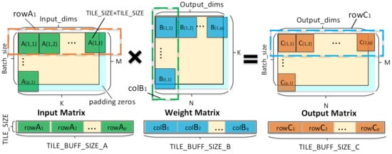
Figure 3.
Matrix partitioning and rearrangement.
4.1.2. Systolic Array
H. T. Kung [24] proposed the systolic array in 1982, which described an array for many dense linear algebraic computations in a parallel computing architecture. The core idea of the systolic array is to reduce the number of accesses to memory through the data flow in the cell array, make the structure more regular and the connections more uniform, and thus improve the operating frequency. As shown in Figure 4a, the upper part of the figure is a traditional computing architecture, in which the processing element (PE) reads data from memory, performs various computations and then writes the results back to memory. The problem with this architecture is that each computation relies on each memory access. The lower part of the figure is systolic array model, presented in the form of a pipeline, that is to say, every PE computation no longer relies on the memory access, only the first array PE to read data from memory, after processing, the result is directly passed on to the next PE, at the same time the first PE can read the next data from the memory, and so on, until the final PE in the array writes the result back to memory per clock cycle. As we can see from the above process, all PEs run in parallel, and the cost of each memory read and write is amortized by multiple PE operations in the array. As a result, systolic array keeps I/O and computation in balance, achieving high throughput at a lower I/O bandwidth, greatly alleviating I/O bottleneck and data access latency in traditional computing model.
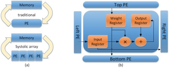
Figure 4.
PE structures. (a) Traditional computing model vs. systolic array model. (b) The structure of PE in systolic array.
The PE structure in the systolic array proposed in this paper is shown in Figure 4b. Each PE contains three storage registers and a multiplier-accumulator (MAC) unit, in which input, weight and output registers are used to store the input data from the left PE, the weight data from the top PE and the temporary output result, respectively, and MAC performs multiplication and addition operations related to the above three values in each clock cycle. The implementation of the systolic array is presented in Algorithm 1, where , , and from Figure 3 are abbreviated as s, , , and , respectively.
| Algorithm 1 Systolic Array Algorithm |
|
Figure 5 shows the systolic array structure with = 16. Input rows and weight columns read from global memory are organized in FIFO form and enter sequentially into the systolic array one by one. In each cycle, the PE on the edge reads the data from the FIFO, while the PE inside reads the input from the adjacent PE on the left and the weight data from the adjacent PE on the top, completes the computation in the MAC unit and stores the intermediate result in local memory. After 16 cycles, the array completes all computations and writes the result data back to global memory. The throughput of the array ultimately depends on the number of DSPs available and the maximum clock frequency that the system can run without timing errors.
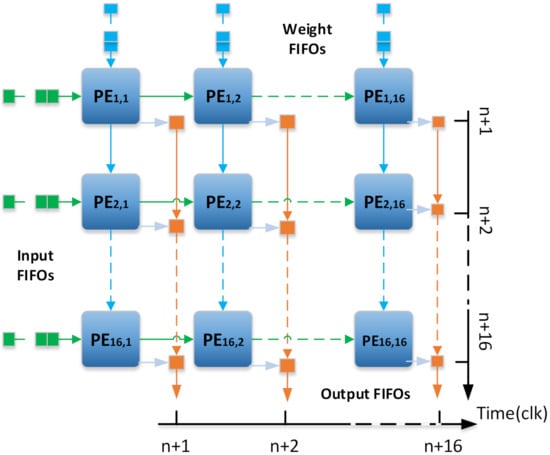
Figure 5.
The structure of the systolic array.
4.2. Activation Function
Nonlinear activation functions such as hyperbolic tangent (tanh) and sigmoid shown in Formulas (1)–(6) have been widely used in neural networks. However, exponential terms appear in function calculation, which makes it very difficult to directly implement them in FPGA. Lookup table [25] and polynomial approximation [26] are commonly used alternatives at present.
Polynomial approximation first divides the function into several intervals. In each interval, the polynomial approximation formula shown in Formula (7) is deployed to transform the complex nonlinear computation into a simple polynomial computation, eliminate the higher-order terms and only retain the low-order terms needed to ensure accuracy. It requires multiple operations on each value to get a result, which consumes many resources and clock cycles.
The lookup method is simple and fast, and the results of nonlinear functions that need to be evaluated are stored in the lookup table in advance. When the nonlinear function needs to be calculated, the result can be read directly from the lookup table, which eliminates the computation process and reduces the computation time. We chose the lookup table method for reasons that are described below.
The size of the lookup table depends on the precision of the computation, and the higher is the precision, the larger is the size. We used fixed-point arithmetic, where a fixed-point number corresponds to a small floating-point interval. In fact, it can be viewed as a quantification operation, with the table size up to 4096, which is an acceptable quantity. Besides, we further reduced the size of the lookup table by exploring more features of tanh and sigmoid activation functions.
(1) Tanh function:
The tanh function is symmetric about the origin, so , and, with this symmetry, we can just look at the positive side of the X-axis.
When x is in the range of (0, 0.25), the result is very close to x, in which interval function can be approximated by .
It is very close to 1 when . Therefore, we only need to generate the lookup table within the range [0.25, 3], which is 176 in size.
In summary, the tanh function in this paper can be approximately expressed as Formula (8).
(2) Sigmoid function:
The sigmoid function is symmetric about the point (0, 0.5), so . With this symmetry, only the positive half axis of the X-axis needs to be considered.
It is very close to 1 when . Therefore, we only need to generate the lookup table in the range [0, 6] with a size of 384.
In summary, the sigmoid function in this paper can be approximately expressed as Formula (9).
The approximated activation function diagram obtained by the lookup table method is shown in Figure 6. As shown in the figure, the approximate function is almost the same as the original function. To compare the lookup table with the polynomial approximation method, we list their indicators in terms of resource usage and latency in Table 1. As shown in Table 1, compared with polynomial approximation, the lookup method greatly saves LUT and FF resources in FPGA, and the latency is also reduced correspondingly. It is necessary to point out that, according to our experimental results, the precision reduction caused by the lookup table method to LSTM can be ignored.

Figure 6.
Comparison between approximated activation function and the original function.

Table 1.
Resource usage and latency comparison between polynomial approximation and lookup table method.
4.3. Element-Wise Computation
Element-wise computation is the last module of this system, which implements Formulas (5) and (6). The entire element-wise computation module allows 16 PEs to run in parallel. The four vectors i, f, o and g obtained through the activation function module will participate in and complete the computation in this module. For each PE, as shown in Figure 7, the four vectors are, respectively, scheduled to element-wise multiplication and addition operations to obtain cell state vector and output vector .
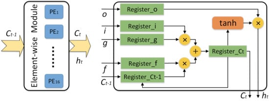
Figure 7.
The structure of the element-wise module.
4.4. Fixed-Point Operation
In general, digital hardware circuits, numerical values are stored in binary format and expressed as floating-point or fixed-point numbers. For an algorithm in the floating-point field, all variables have a large number of bits (e.g., double-precision floats are 64-bit, single-precision floats are 32-bit and half-precision floats are 16-bit). Its operation requires a lot of logic and triggers (FF), which means a lot of chip resources and correspondingly high power consumption. In practical application, if the inference of deep learning does not affect the final inference result, it allows us to conduct targeted data compression, so as to improve the utilization rate of resources on the FPGA chip. The resulting errors are often so small as to be negligible.
In this paper, we use a pair of numbers (M and E) to represent a class of fixed-point data, where M and E represent the binary bit number of the integer and decimal parts, respectively. There is an extra bit in the header to indicate whether the data value is positive or negative. Given a pair of arguments (M, E), the floating-point number x can be rounded to the nearest mode [27]:
where , which equals to , is the smallest positive number under the given fixed format. is the largest integer multiple of and it is less than or equal to x and ranges from to . We can then convert floating-point numbers to (M, E) fixed-point numbers by using the following formula:
After fully studying the model parameters we trained, we set M as 5 and E as 6 according to all numerical ranges. To assess the benefits of fixed-point number (5, 6), we implemented addition and multiplication between two numbers to compare its resource utilization with FP32 and FP16 floating-point types, running with a target clock frequency of 300 Mhz. To simultaneously evaluate the accuracy that may be caused by the reduction of numerical bits, the widely adopted perplexity is used as the index of the model prediction accuracy for measuring. The lower is the perplexity, the higher is the prediction accuracy, and vice versa. Table 2 shows LUT usage, latency and perplexity for FP32, FP16 and fixed-point number (5, 6). It can be seen that using fixed-point number to replace floating-point number for multiplication and addition can greatly save FPGA on-chip resources and reduce the latency of operation, while it has a very limited impact on the perplexity.

Table 2.
Comparison among different datatypes.
5. Integration with Caffe
Caffe is a widely-used open-source deep learning framework that allows for rapid deployment of deep learning networks for training or inference on a GPU or CPU. Caffe emphasizes hierarchy and neural networks develop on a hierarchical basis. In the Caffe framework, a layer is the basic computing unit, which implements the functions of the deep neural networks such as convolution and pooling. In addition, it allows developers to customize a new layer as needed. Caffe can be easily used for deep neural network inference by providing a configuration file that describes the type and order of the required layers, as well as a pre-trained Caffe model in which weight data are stored. Caffe automatically converts a configuration file into a running network based on the loaded weight data.
In the integration with the Caffe framework, we used the SDAccel development environment provided by Xilinx, which develops the FPGA program using the OpenCL programming model [28]. OpenCL model divides the FPGA program into two parts: the host side and the kernel side. The CPU is responsible for running the host code, programming FPGA, launching the kernel on FPGA and transferring data between the host memory and the FPGA global memory. The kernel executor is the FPGA, which runs the kernel code and implements the computing tasks to be accelerated.
To take advantage of the convenience and flexibility of Caffe, we propose a general LSTM acceleration system based on Caffe, which is co-operated by CPU and FPGA. Figure 8 gives an overview of the LSTM integrated Caffe. Three points need to be mentioned when comparing with the original Caffe:
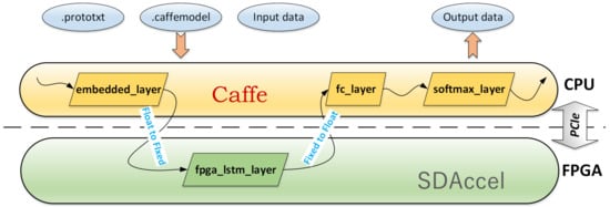
Figure 8.
Integration with Caffe.
(1) We customize a new layer called FPGA_LSTM_Layer. The main functions of the FPGA_LSTM_Layer include launching and releasing the FPGA kernel and performing conversion of numerical types, converting floating-point numbers to fixed-point numbers before launching the FPGA kernel and converting data back to floating-point Numbers after the FPGA kernel is released.
(2) Although only FPGA_LSTM_Layer runs on the FPGA and the other layers run on the CPU throughout the framework, the FPGA_LSTM_Layer covers over 90% of the total amount of computation, so we still get network computing accelerated.
(3) Since FPGA compilation requires circuit synthesis and routing, which is often time-consuming and takes several hours, we use the pre-compiled bitstream file at runtime. FPGA programming can be completed when the system starts to load the network data.
6. Experimental Results
6.1. Experimental Setup
Hardware platforms used in the framework proposed in this paper include host platform and FPGA platform: (1) The host platform adopted Intel Pentium G2030 CPU. The CPU was running at 3 GHz. (2) The FPGA platform used the Xilinx KCU1500 FPGA acceleration development board, including the Kintex UltraScale XCKU115-2FLVB2104E FPGA and 16 GB external DDR4 memory, connecting to the host through PCIe 2.0 × 8 interface. The FPGA ran at 300MHz. We used Vivado 2016.3 software to design FPGA IP and SDAccel 2017.1 to generate the bitstream file that can be programmed and run on FPGA. In addition, the Nvidia Geforce GTX 960 device was used for comparison.
Our experimental data came from COCO 2014 dataset. COCO 2014 dataset is a large dataset commonly used for image captioning. It contains 162k pictures, and each picture contains at least five sentences to describe the theme information of the picture. All the description statements were extracted to build a language dataset, and Caffe was used to train an LSTM language model. The input feature was an 8801-dimensional vector, and the dimension of the embedded layer and the LSTM layer were both 512.
Given a word, such as “play”, the language model can generate the next word that conforms to human natural language habits, such as “basketball” and “game”. Further, it can generate a complete sentence by calling the language model multiple times, as shown in Figure 9.

Figure 9.
An example for generating sentence by LSTM language model.
6.2. Resource Utilization
To represent the advantages of the optimization method proposed in this paper, we conducted the following five groups of comparative experiments: (1) Non-optimization: No optimization method was used. (2) Without systolic array: Matrix multiplication was used with the conventional method. (3) Without lookup table: The activation function was implemented by polynomial approximation. (4) Without fixed-point: Floating-point number (FP32) was used for operation. (5) Optimization: The three optimization methods discussed in this paper were used.
We used Vivado 2016.3 to give a comprehensive report on the designed IP. The maximum available quantities of BRAM, DSP48E, FF and LUT on the used FPGA are 2160, 2760, 663,360 and 331,680, respectively. In the report, resource utilization is defined as the percentage of used resources in the maximum available amount. When the target frequency is set to 300 MHz, resource utilization is shown in Table 3. If the systolic array is not used, the system concurrency is not high and the efficiency of the system decreases. The systolic array can make full use of the chip resources and improve the working efficiency of the system. Without a lookup table method for activation function, the usage of the LUT will exceed the maximum number available. Without fixed-point arithmetic, there will be BRAM deficiency. It can be seen that the fixed-point arithmetic and lookup table method of activation function greatly save BRAMs and LUTs of the system. The savings in resources such as LUT allow us to put more PEs in each system, making the system more concurrent.

Table 3.
Resource utilization when deploying different optimization methods.
6.3. Speed and Energy Efficiency
Speed and energy efficiency are commonly used to evaluate the performance of the FPGA design. The speed of different platforms can be measured by latency, which in this paper represents the execution time required to predict a word. Energy efficiency is the amount of energy consumed per word, which is calculated by multiplying the power by the latency time. The most important goals of our acceleration engine are to optimize latency and efficiency. The smaller is the latency or the higher is the energy efficiency, the better is the performance of FPGA design. To evaluate the performance of our LSTM acceleration engine and the advantages of integrating with Caffe, we took the LSTM network inference without any optimization implemented on a CPU as the benchmark, which was written in c++ language. After integrating the LSTM acceleration engine into the Caffe framework, we used CPU, GPU and FPGA as acceleration devices to run the same LSTM model and compared the acceleration and energy efficiency of three different platforms. The results are shown in Table 4 and Figure 10. It can be seen that, in Caffe, the CPU can accelerate six times compared with the baseline. This is mainly because the MKLBLAS library is used in the Caffe framework to optimize the matrix operation and make full use of multiple cores on the CPU to execute multithreading. Under the framework of Caffe, compared with CPU and GPU, our acceleration engine achieves 8.8 and 2.2 times acceleration and 16.9 and 9.6 times energy efficiency, respectively.

Table 4.
Comparison among different platforms.
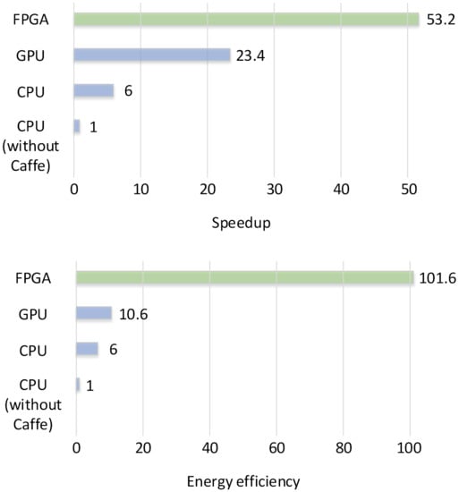
Figure 10.
Speedup and energy efficiency on different platforms.
7. Acceptability
In general, the implementation complexity and performance of deep neural networks depend on the tasks to be completed. For example, processing the MNIST dataset for digit recognition is much simpler than the ImageNet dataset for image classification. How to decide whether an FPGA optimization implementation scheme is acceptable under a given task is the issue discussed in this section. We divide the above-mentioned indicators for evaluation into three categories:
(1) Accuracy index: Perplexity is adopted as the index of model prediction accuracy.
(2) Performance index: It is measured with energy efficiency, which can be calculated from power, latency (speedup) and other indicators.
(3) Resource index: It is the utilization of BRAM, DSP, FF and LUT resources in FPGA.
Acceptability is defined as follows:
where is perplexity, is energy efficiency, is resource, is the indicator of the baseline scheme, and are the influence factors of and and . As we can see, the acceptability at baseline is 1. When perplexity increases, that is, the accuracy decreases, the acceptability decreases. When energy efficiency increases, acceptability will increase. When resource utilization decreases, acceptability also increases. The trade-off between these factors can be presented in the acceptability index, since there is an interplay between them, for instance, achieving higher accuracy typically requires more complex models (a larger number of floating-point operations, more unpruned weights, etc.), which can impact the energy efficiency and the resource.
Concerning the setup of and , it is necessary to increase in consideration of different application scenarios, such as when the hardware cost is very important because the amount of resource utilization will directly lead to the upgrade or degradation of the used devices, which is directly related to the cost. In practice, each application has different requirements, such as energy and power importance in embedded devices with limited battery capacity (e.g., smartphones, smart sensors, drones and wearable devices) or strict power ceilings due to cooling costs in cloud data centers. Low latency is required for real-time interactive applications. Large latency is unacceptable for applications such as real-time translation. Therefore, further planning can be considered for each sub-item in the item.
8. Conclusions
In this paper, we implement an FPGA-based LSTM acceleration engine. To solve the limited resources and performance challenges, we use the systolic array for matrix multiplication, the fixed-point arithmetic for basic operation, the lookup table for activation function and deeply optimize the LSTM implementation on FPGA. To achieve rapid deployment of the acceleration engine, we integrate it into Caffe, one of the most popular deep learning frameworks. Experimental results show that our LSTM acceleration engine is superior to CPU and GPU in terms of performance and energy efficiency. The integration of the LSTM acceleration engine with Tensorflow could be a future effort. The acceptability of the optimization scheme is also an index worthy of sustainable improvement.
Author Contributions
Conceptualization, D.H., J.H. and J.L.; methodology, D.H.; software, J.H.; validation, D.H., J.H. and J.Y.; formal analysis, D.H., J.H. and Q.Y.; investigation, D.H. and J.L.; resources, J.H. and J.Y.; data curation, D.H. and Q.Y.; writing—original draft preparation, J.H. and D.H.; writing—review and editing, D.H., and Y.Y.; visualization, D.H., and J.H.; supervision, J.Y. and Y.Y.; project administration, Y.Y.; and funding acquisition, J.Y., Y.Y. and J.L. All authors have read and agreed to the published version of the manuscript.
Funding
This work was supported partially by the National Natural Science Foundation of China (61671078, 61701031 and 61801035), Beijing Natural Science Foundation (L182024), basic BUPT scientific research project (500418763), research project of BUPT (142208180205), Science and Technology on Space Intelligent Control Laboratory (6142208180205), Funds of Beijing Laboratory of Advanced Information Networks and Beijing Key Laboratory of Network System Architecture and Convergence of BUPT, the Fundamental Research Funds for the Central Universities (2018XKJC04), the National Key Research and Development Program of China (2017YFB0802701) and the 111 Project of China (B08004 and B17007).
Acknowledgments
This work was conducted on the platform of Center for Data Science of BUPT.
Conflicts of Interest
The authors declare no conflict of interest.
References
- Graves, A.; Jaitly, N.; Mohamed, A. Hybrid speech recognition with deep bidirectional lstm. In Proceedings of the 2013 IEEE Workshop on Automatic Speech Recognition and Understanding, Olomouc, Czech Republic, 8–12 December 2013; pp. 273–278. [Google Scholar]
- Sutskever, I.; Vinyals, O.; Le, Q.V. Sequence to sequence learning with neural networks. arXiv 2014, arXiv:1409.3215. [Google Scholar]
- Hochreiter, S.; Schmidhuber, J. Long short-term memory. Neural Comput. 1997, 9, 1735–1780. [Google Scholar] [CrossRef]
- Appleyard, J.; Kocisky, T.; Blunsom, P. Optimizing performance of recurrent neural networks on gpus. arXiv 2016, arXiv:1604.01946. [Google Scholar]
- Collobert, R.; Bengio, S.; Mariethoz, J. Torch: A Modular Machine Learning Software Library; Idiap: Martigny, Switzerland, 2002. [Google Scholar]
- Seide, F.; Agarwal, A. Cntk: Microsoft’s open-source deeplearning toolkit. In Proceedings of the 22nd ACM SIGKDD International Conference on Knowledge Discovery and Data Mining, San Francisco, CA, USA, 13–17 August 2016; p. 2135. [Google Scholar]
- Abadi, M.; Barham, P.; Chen, J.; Chen, Z.; Davis, A.; Dean, J.; Devin, M.; Ghemawat, S.; Irving, G.; Isard, M.; et al. Tensorflow: A system for largescale machine learning. In Proceedings of the 12th USENIX Symposium on Operating Systems Design and Implementation (OSDI 16), Savannah, GA, USA, 2–4 November 2016; pp. 265–283. [Google Scholar]
- Jia, Y.; Shelhamer, E.; Donahue, J.; Karayev, S.; Long, J.; Girshick, R.; Guadarrama, S.; Darrell, T. Caffe: Convolutional architecture for fast feature embedding. In Proceedings of the 22nd ACM international conference on Multimedia, Orlando, Florida, USA, 3–7 November 2014; pp. 675–678. [Google Scholar]
- Ortiz, M.; Cristal, A.; Ayguadé, E.; Casas, M. Low-precision floating-point schemes for neural network training. arXiv 2018, arXiv:1804.05267. [Google Scholar]
- DiCecco, R.; Sun, L.; Chow, P. Fpga-based training of convolutional neural networks with a reduced precision floating-point library. In Proceedings of the 2017 International Conference on Field Programmable Technology (ICFPT), Melbourne, Australia, 11–13 December 2017; pp. 239–242. [Google Scholar]
- Gupta, S.; Agrawal, A.; Gopalakrishnan, K.; Narayanan, P. Deep learning with limited numerical precision. In Proceedings of the International Conference on Machine Learning, Lille, France, 6–11 July 2015; pp. 1737–1746. [Google Scholar]
- Lian, X.; Liu, Z.; Song, Z.; Dai, J.; Zhou, W.; Ji, X. High-performance fpga-based cnn accelerator with block-floating-point arithmetic. In IEEE Transactions on Very Large Scale Integration (VLSI) Systems; IEEE: Piscataway, NJ, USA, 2019; Volume 27, pp. 1874–1885. [Google Scholar]
- Lu, L.; Liang, Y.; Xiao, Q.; Yan, S. Evaluating fast algorithms for convolutional neural networks on fpgas. In Proceedings of the 2017 IEEE 25th Annual International Symposium on Field-Programmable Custom Computing Machines (FCCM), Napa, CA, USA, 30 April–2 May 2017; pp. 101–108. [Google Scholar]
- Kala, S.; Jose, B.R.; Mathew, J.; Nalesh, S. High-performance cnn accelerator on fpga using unified winograd-gemm architecture. IEEE Trans. Very Large Scale Integr. (VLSI) Syst. 2019, 27, 2816–2828. [Google Scholar] [CrossRef]
- Bai, L.; Zhao, Y.; Huang, X. A CNN accelerator on FPGA using depthwise separable convolution. IEEE Trans. Circuits Syst. II Express Briefs 2018, 65, 1415–1419. [Google Scholar] [CrossRef]
- Yu, Y.; Zhao, T.; Wang, K.; He, L. Light-opu: An fpga-based overlay processor for lightweight convolutional neural networks. In Proceedings of the 2020 ACM/SIGDA International Symposium on Field-Programmable Gate Arrays, Seaside, CA, USA, 23–25 February 2020; pp. 122–132. [Google Scholar]
- Ma, Y.; Cao, Y.; Vrudhula, S.; Seo, J.S. Performance modeling for cnn inference accelerators on fpga. IEEE Trans. Comput.-Aided Des. Integr. Circuits Syst. 2020, 39, 843–856. [Google Scholar] [CrossRef]
- Cariow, A.; Cariowa, G. Minimal filtering algorithms for convolutional neural networks. arXiv 2020, arXiv:2004.05607. [Google Scholar]
- Cariow, A.; Paplinski, J.P. Some algorithms for computing short-length linear convolution. Electronics 2020, 9, 2115. [Google Scholar] [CrossRef]
- Chang, A.X.M.; Martini, B.; Culurciello, E. Recurrent neural networks hardware implementation on FPGA. arXiv 2015, arXiv:1511.05552. [Google Scholar]
- Han, S.; Kang, J.; Mao, H.; Hu, Y.; Li, X.; Li, Y.; Xie, D.; Luo, H.; Yao, S.; Wang, Y.; et al. Ese: Efficient speech recognition engine with sparse lstm on fpga. In Proceedings of the 2017 ACM/SIGDA International Symposium on Field-Programmable Gate Arrays, Monterey, CA, USA, 22–24 February 2017; pp. 75–84. [Google Scholar]
- Wang, S.; Li, Z.; Ding, C.; Yuan, B.; Qiu, Q.; Wang, Y.; Liang, Y. February. C-LSTM: Enabling efficient LSTM using structured compression techniques on FPGAs. In Proceedings of the 2018 ACM/SIGDA International Symposium on Field-Programmable Gate Arrays, Monterey, CA, USA, 25–27 February 2018; pp. 11–20. [Google Scholar]
- Cao, S.; Zhang, C.; Yao, Z.; Xiao, W.; Nie, L.; Zhan, D.; Liu, Y.; Wu, M.; Zhang, L. Efficient and effective sparse LSTM on FPGA with bank-balanced sparsity. In Proceedings of the 2019 ACM/SIGDA International Symposium on Field-Programmable Gate Arrays, Seaside, CA, USA, 24–26 February 2019; pp. 63–72. [Google Scholar]
- Kung, H.T. Why systolic architectures? IEEE Comput. 1982, 15, 37–46. [Google Scholar] [CrossRef]
- Lin, C.W.; Wang, J.S. A digital circuit design of hyperbolic tangent sigmoid function for neural networks. In Proceedings of the 2008 IEEE International Symposium on Circuits and Systems, Seattle, WA, USA, 18–21 May 2008; pp. 856–859. [Google Scholar]
- Ferreira, J.C.; Fonseca, J. An fpga implementation of a long short term memory neural network. In Proceedings of the 2016 International Conference on ReConFigurable Computing and FPGAs (ReConFig), Cancun, Mexico, 30 November–2 December 2016; pp. 1–8. [Google Scholar]
- Kornerup, P.; Muller, J.M.; Panhaleux, A. Performing arithmetic operations on round-to-nearest representations. IEEE Trans. Comput. 2010, 60, 282–291. [Google Scholar] [CrossRef]
- Stone, J.E.; Gohara, D.; Shi, G. Opencl: A parallel programming standard for heterogeneous computing systems. Comput. Sci. Eng. 2010, 12, 66–72. [Google Scholar] [CrossRef] [PubMed]
Publisher’s Note: MDPI stays neutral with regard to jurisdictional claims in published maps and institutional affiliations. |
© 2021 by the authors. Licensee MDPI, Basel, Switzerland. This article is an open access article distributed under the terms and conditions of the Creative Commons Attribution (CC BY) license (http://creativecommons.org/licenses/by/4.0/).