Article

High Reliability UWB Monopole Antenna Using Planar Embedded Resistance for Mars Subsurface Exploration

1
Aerospace Information Research Institute, Chinese Academy of Sciences, Beijing 100190, China
2
Key Laboratory of Electromagnetic Radiation and Sensing Technology, Chinese Academy of Sciences, Beijing 100190, China
3
School of Electronic, Electrical and Communication Engineering, University of Chinese Academy of Sciences, Beijing 100049, China
*
Author to whom correspondence should be addressed.
Electronics 2021, 10(6), 682; https://doi.org/10.3390/electronics10060682
Submission received: 18 February 2021 / Revised: 6 March 2021 / Accepted: 10 March 2021 / Published: 14 March 2021
(This article belongs to the Section Microwave and Wireless Communications)

Abstract

:
The Tianwen-1 of China is expected to land and explore on the planet Mars in May 2021, carrying a Mars Rover-mounted Subsurface Penetrating Radar (RoSPR) system. A VHF band ultra-wideband (UWB) monopole antenna integrated on the Mars Rover, and described in this paper, has been designed for the subsurface exploration of Mars tens of meters deep. Conventional antenna design methods usually prove difficult in taking into account several key parameters such as miniaturization, broadband characteristics and radiation efficiency. Moreover, there is almost no special research on the reliability of antennas. For this purpose, a miniaturized air-coupled monopole antenna integrated with the Mars Rover has been designed. The overall length of the antenna is 0.13 λ at the lowest operating frequency. In addition, the classical Wu–King profile is improved, which not only satisfies the operating bandwidth of the antenna, but also increases the gain by 3–4 dB. In the design, the innovative application of planar embedded resistance greatly enhances the reliability of the antenna and thereby ensures that the antenna can work on Mars for a long term. This is the first application of this antenna design method in the aerospace field. Because it is difficult to test the low-frequency antenna accurately, a 1:4 scale model of the antenna and Rover is fabricated to equivalently measure the radiation characteristics of the antenna. Furthermore, the performance and practicability of the antenna and radar system are verified on the glacier.

1. Introduction

China’s first Mars exploration mission, named Tianwen-1 (TW-1), was launched on 23 July 2020 and is expected to land on the surface of Mars in May 2021 for scientific exploration [1]. TW-1 is equipped with a Mars Rover-mounted Subsurface Penetrating Radar (RoSPR) system for detecting subsurface geological structures of Mars. The main scientific objective of RoSPR is to characterize the thickness and layered structure of Martian soil. In the deep exploration mode, the operation band of the radar is 30–90 MHz, and the detection depth ranges from 10 m to 100 m with a depth resolution of about 2.2 m. According to the overall configuration of the Rover, the length of the antenna is limited to 1.35 m, which is only 0.13 λ of the lowest operating frequency, and only lightweight rod antennas can be installed on the Rover. Under this restriction, the relative bandwidth of the antenna reaches 100%, which brings challenges to the antenna design. Furthermore, the RoSPR antenna is exposed to the Martian environment for a long term, and it also needs to be able to withstand the thermal and mechanical environment of the launch and working stages.
In ground applications, several types of antenna are frequently employed in ultra-wideband (UWB) radar systems, such as bowtie/dipole antennas [2,3], monopole antennas [4], horn antennas [5], Vivaldi antennas [6] and slot antennas [7]. The size of RoSPR antennas is strictly limited, so bowtie/dipole antennas and monopole antennas are possible solutions. In recent years, a variety of bowtie antennas with good performance have been proposed [8,9,10], but the sizes of these antennas are all above 0.3 λ of the lowest operating frequency. A small bowtie antenna below 0.1 λ has been designed [11]; however, its gain is less than −20 dB, which makes it difficult to apply in practice. Most of these bowties are used as ground-coupled antennas. When the antenna works in the air-coupled state, due to the loss of the ground dielectric loading effect, the antenna size will be larger than the ground-coupled one [12,13,14]. The bandwidth of monopole antennas is usually increased by widening the antenna arm [15,16,17]. The radiation efficiency of this kind of antenna is higher than the loaded one, but the electric size is up to 0.4 λ of the lowest frequency. A monopole antenna with a size of 0.17 λ was miniaturized by parasitic structures [18], but its structure cannot be integrated with the Rover. Therefore, the design of a miniature UWB monopole antenna integrated with the Rover, and able to adapt to the Martian environment, has become the focus of the research.
In the past 20 years, Mars has been explored many times. Missions to explore the geological structures of Mars include the Mars advanced radar for subsurface and ionospheric sounding (MARSIS) system onboard the Mars Express spacecraft, and the Mars Shallow Radar Sounder (SHARAD) system on board the National Aeronautics and Space Administration (NASA)/ Jet Propulsion Laboratory (JPL)’s Mars Reconnaissance Orbiter spacecraft. The MARSIS system employed a dipole antenna with a length of 40 m, an operating frequency bandwidth of 1.3–5.3 MHz, and an instantaneous bandwidth of 1 MHz [19]. The SHARAD system also used a dipole antenna with a length of 7.5 m and a frequency bandwidth of 15–25 MHz [20,21]. The above radar systems all used an inductance and capacitance (LC) network for impedance matching, whose matching band is generally less than 50%. Due to the employment of capacitors and inductors, the phase linearity of the antenna in the broadband is deteriorated, resulting in distortion of the signal to a certain extent. In order to solve the above problems, an improved Wu–King profile was proposed in the design of the RoSPR antenna [22], and the feed port is matched by a transmission line transformer [23].
The resistance-loaded dipole, or monopole antenna, can be designed as continuous loading, discrete loading, or terminal loading [24,25,26]. The continuous loading antenna needs to include a resistance layer on the whole arm, which has high requirements for processing technology. The strength of the resistance layer, as well as the poor adhesion between the resistance layer and the antenna arm, often leads to undesirable damage resulting from mechanical stress and friction. The lumped resistor is usually used in the discrete loading and terminal loading [2]. In high-level vibration or long-term alternating temperature environments, the resistor and its solder joints are easily damaged due to mechanical stress and thermal stress, so the reliability is insufficient in aerospace applications. Considering the aforementioned techniques, a monopole antenna with discrete loading based on planar embedded resistance is designed in this study. The antenna is loaded discretely with seven relatively large areas of plane-embedded resistance, avoiding the use of lumped elements. As a result, the design improves the power capacity and reliability of the antenna, rendering its ability to adapt to the environment of deep space and Mars.
In general, the radiation characteristics of an antenna are mainly measured in the microwave anechoic chamber. However, the working frequency band of chambers is usually higher than 100 MHz, which is not applicable for the RoSPR antenna. On the other hand, the RoSPR antenna is designed and integrated with the Rover as a whole; therefore, it is necessary to install a complete Rover model during the test, which imposes higher requirements on the turntable and site. In order to measure the RoSPR antenna, a 1:4 scaled model of the Rover and antenna is designed and tested in the open area test site (OATS). The antennas are integrated with the radar system, whose detection ability is verified in Touming-Mengke glacier No.29 in Gansu Province, China.
In this article, we will focus on the research of a miniaturized UWB monopole antenna integrated with the Rover. An improved resistance loading profile based on the Wu–King profile is proposed, which satisfies the bandwidth of the antenna and increases the radiation efficiency. Moreover, for the first time in the aerospace field, the planar embedded resistance is applied to antenna design, which improves the reliability of the antenna and expands the application field of the loaded antenna. Section 2 describes the design and the geometry of the antenna. In Section 3, the insufficiencies of the existing methods in reliability are introduced, and the solutions are proposed and verified by reliability tests. In Section 4, the measured and simulated antenna results are presented and analyzed. Section 5 describes the method and results of experimental verification of the RoSPR, which proves the effectiveness of the antenna. Section 6 and Section 7, respectively, provide the discussion and conclusion.

2. Design and Geometry

The ground-penetrating radar (GPR) antenna, especially in the VHF band and below, is usually designed as a ground coupled dipole or bowtie antenna. In order to obtain broadband characteristics, these antennas usually use the Wu–King profile to change the current distribution on the antenna arms. The expression of loading resistances is shown in Formula (1) [22].
R z = ξ 0 Ψ 2 π ( L z )
where ξ 0 = μ 0 / ε 0 = 120 π Ω, Ψ is the scale factor, L is the length of the antenna arm and z is the distance to the feed point. It can be concluded that the resistance loading on the antenna arm can be expressed as Formula (2):
R z = R L z = 60 Ψ L z
where R is the antenna input impedance and Ψ is a plural number, which is usually replaced by | Ψ | in engineering, and its empirical formula is as follows:
| Ψ | = 2 ln ( 2 L / a ) 3
where a is the radius of the antenna arm.
Some scholars have studied the efficiency of the Wu–King profile. If the antenna is loaded according to the non-reflection profile, the efficiency of the antenna is low. However, the radiation efficiency can be improved by adjusting the loading factor and moderately sacrificing the reflection characteristics of the antenna [27]. To improve the efficiency of the monopole antenna and ensure that the feed port is easy to match, the Wu–King profile is improved. Instead of determining the load resistance by the slenderness ratio of the arms, the input resistance of the antenna is directly set to R = 200 Ω . The antenna arm is equally divided into N segments with a segment length of l . The midpoint of segment i is z i , and the loading resistance value of this point is shown in Formula (4). Such a discrete resistor loading profile can reduce the input impedance of the antenna for easy matching and has a higher radiation efficiency than the typical Wu–King loading profile.
R z i = R L z i × l
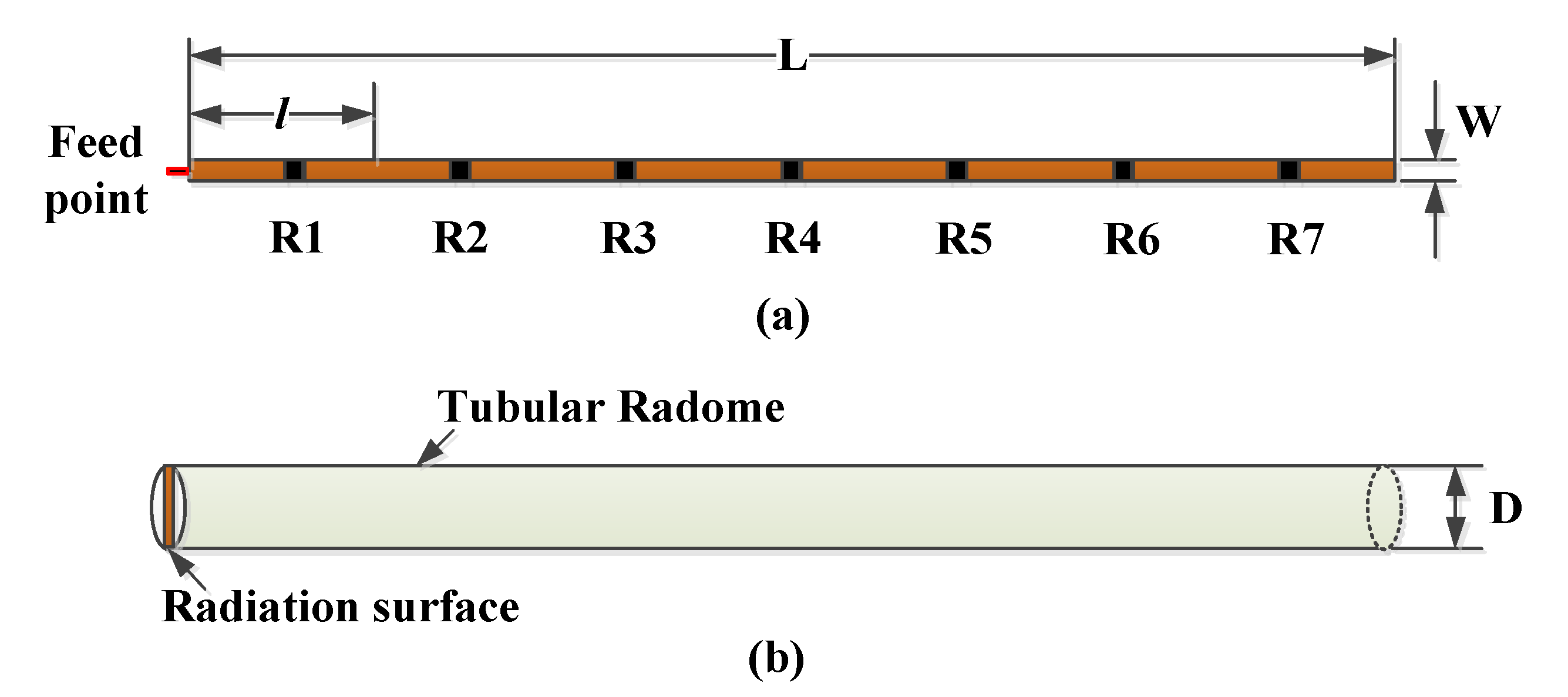
The antenna arm of the RoSPR is 1350 mm in length and 10 mm in width. The antenna arm is divided into seven segments equally, and resistance loading is introduced in the middle of each segment. The structure of the antenna arm is shown in Figure 1. In order to realize the broadband operation of the antenna, a 1:4 transmission line transformer is used for impedance matching. The transmitting antenna and receiving antenna are respectively installed on both sides of the Rover’s top plate, with a spacing of 1050 mm, and are extended forward through the locking and releasing mechanism. To ensure that the Rover can climb slopes more than 30° while moving, the antenna is tilted up by 15° and its installation status is shown in Figure 2.

3. Reliability Design and Test

In order to meet the bandwidth requirements of the system, the monopole antenna must be loaded. In the loading antenna design, there are usually capacitive loading, resistance loading, and hybrid loading. The capacitive loading antenna has high radiation efficiency [28,29]. However, with the band of 30–90 MHz, the lumped capacitor must be used for loading because of the large capacitance required for loading. When the lumped capacitor is mounted on the printed circuit board (PCB) of the antenna arm, it is difficult for its solder joints to withstand high-level mechanical vibration and thermal stress. Consequently, it is easy for cracks to occur in the application, which reduces the reliability of the antenna. In addition, the capacitors will introduce the nonlinear factor of phase, resulting in the distortion of the radiation signal, which is not conducive to the operation of the RoSPR.
The resistance-loaded antenna has low radiation efficiency, but good phase linearity, so it is widely used in UWB GPR systems. Generally, resistance loading can be employed in two ways: continuous loading and discrete loading. Continuous loading is achieved by a coating resistance layer on the antenna arm. This kind of antenna has excellent reflection characteristics, but the adhesion between the resistance layer and the antenna arm is low, making it easy to peel off, even fall off, in long-term operation in a temperature-alternating environment In addition, since the thickness of the resistance layer is less than 1 um, and the strength is insufficient, it is easily damaged due to external forces, resulting in the failure of the antenna. Discrete resistor loading is the most commonly used method. In the ground environment, the discrete loading with a lumped resistor is a perfect solution. However, in aerospace applications, the discrete resistor loading has the same difficulty as the lumped capacitor loading.
In order to solve the above problems, a discrete loading scheme using planar embedded resistance is proposed. In the loading position, planar embedded resistors with the same width as the antenna arm are designed to replace the lumped resistors, avoiding the lumped elements and solder joints in the antenna. Because of the large area of planar resistance, the antenna has a higher power capacity. Even if part of the resistance is damaged, the antenna may still work normally. This design greatly improves the reliability of the antenna. The resistance layer can withstand the average power of 0.138 mW/mil2. Table 1 lists the power capacity of each embedded resistor. The structure of the embedded resistor is shown in Figure 3. The resistance layer is made of Ni/P alloy with a thickness of 0.2 um.
In order to improve the reliability of the antenna, we also focused on the material selection and structure design. The radiation surface of the antenna is made of an 85N polyimide substrate of Arlon with a thickness of 1 mm, a relative dielectric constant of 4.2 and a loss tangent of 0.01. It has excellent temperature performance and mechanical properties. Meanwhile, to improve the structural strength of the antenna arm, a tubular radome was designed. The radome is made of quartz-fiber/epoxy composite material with a thickness of 0.6 mm as shown in Figure 1b. The antenna arm is a long and thin slender rod-shaped structure, which will inevitably form a cantilever when folded. The longer the cantilever is, the greater the deformation and stress will be. To reduce the deformation and stress, the antenna was designed with two sections. When the antenna is folded, the length of the cantilever is shortened. When working, the antenna is deployed by initiating an explosive device and then driven by a scroll spring at joints. The structural design of the antenna is shown in Figure 4.
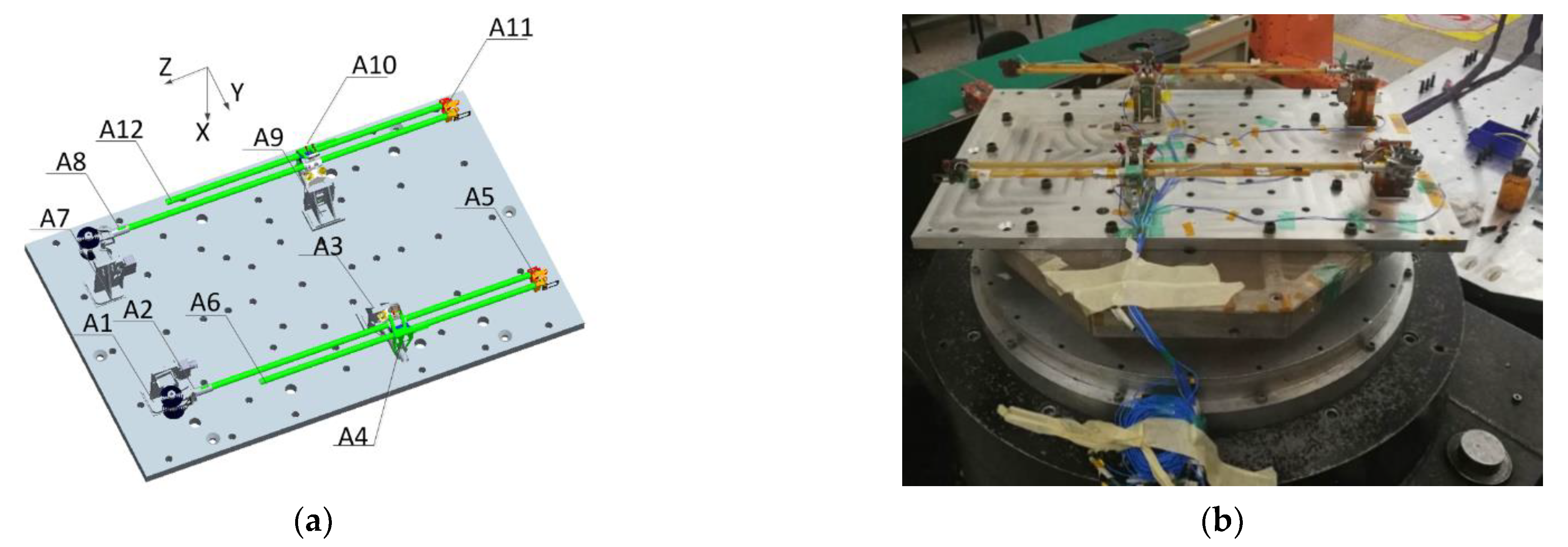
The vibration test (random and sinusoidal), acceleration test and impact test were conducted to verify the reliability of the antenna during the launch and landing stages, In the sinusoidal vibration test, the antenna underwent the harshest trial. The peak value of the mechanical response at the A6 point as shown in Figure 5a reached 352 g (@ 40.2 Hz) with the excitation of 10 g. Figure 5b is the X-axis vibration test of the antenna.
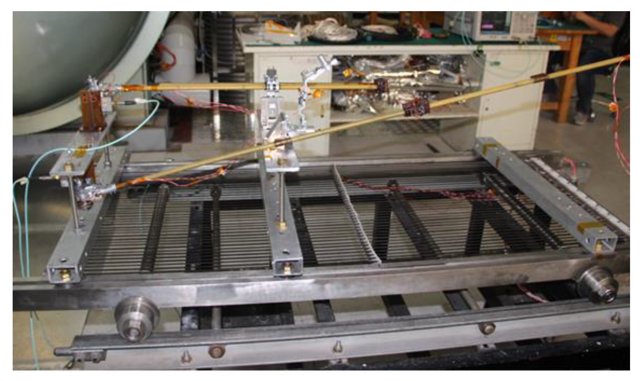
Furthermore, various thermal tests including the thermal vacuum test, thermal cycle test and high and low temperature storage tests were carried out to validate the temperature adaptability. During the thermal test, the temperature alternating range is from −130 °C to +70 °C. The accumulated alternating cycles are over 30 times, and the highest temperature changing rate is over 10 °C/min. Figure 6 shows the thermal test status. Throughout all the mechanical and thermal tests, the appearance and performance of the antenna maintain as almost the same, which proves its adaptability to the environment of outer space and ability to operate on Mars for a long term.

4. Simulation and Measurement

In the VHF band, the reflection characteristics of the antenna are obviously affected by the testing environment; therefore, it needs to be tested in an open area. In addition, because the RoSPR antenna is integrated with the Rover, the antenna must be installed on the Rover model during the test. Figure 7 shows that good impedance matching is achieved. In detail, the voltage standing wave ratio (VSWR) of the antenna is less than 3.0 in the operation band from 30 MHz to 100 MHz. Within 40–80 MHz, the VSWR remains under 2.0.
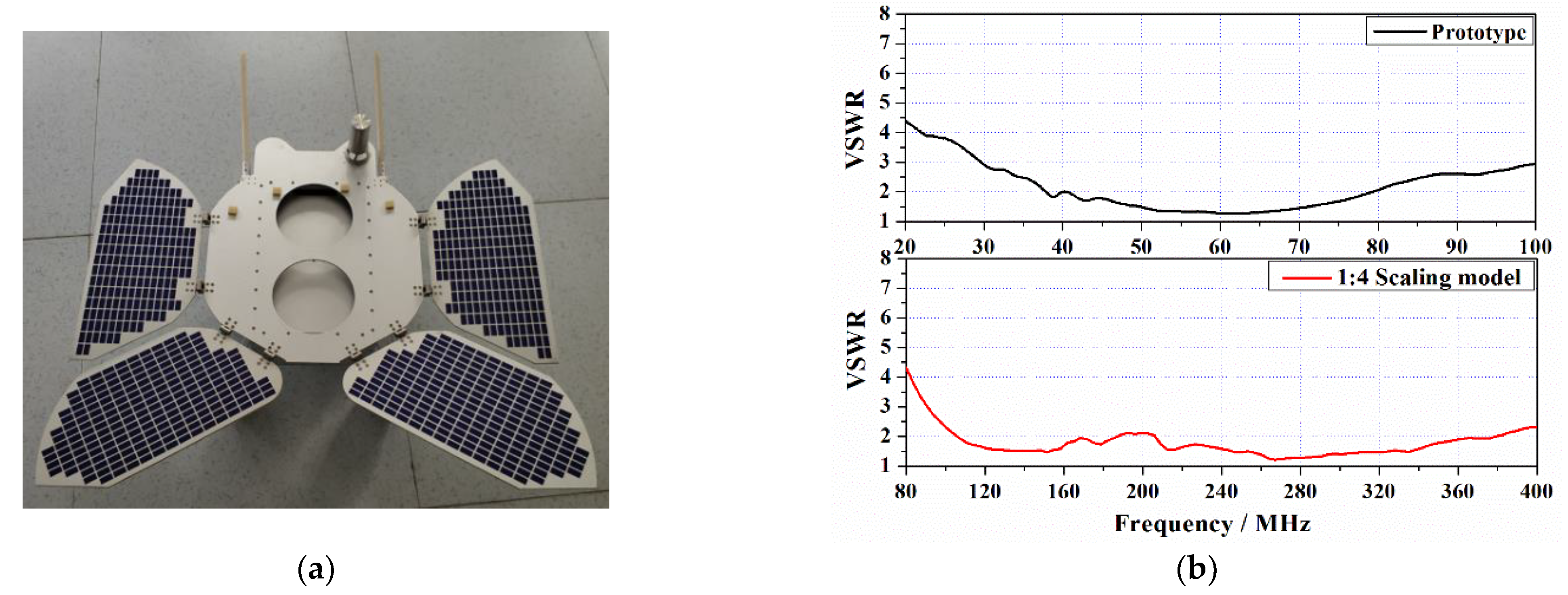
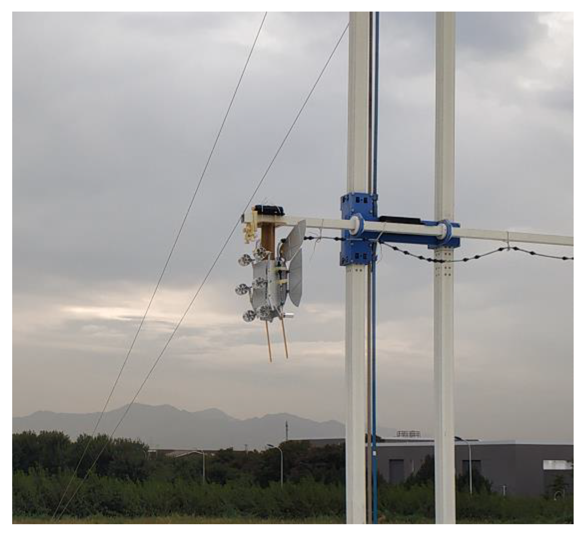
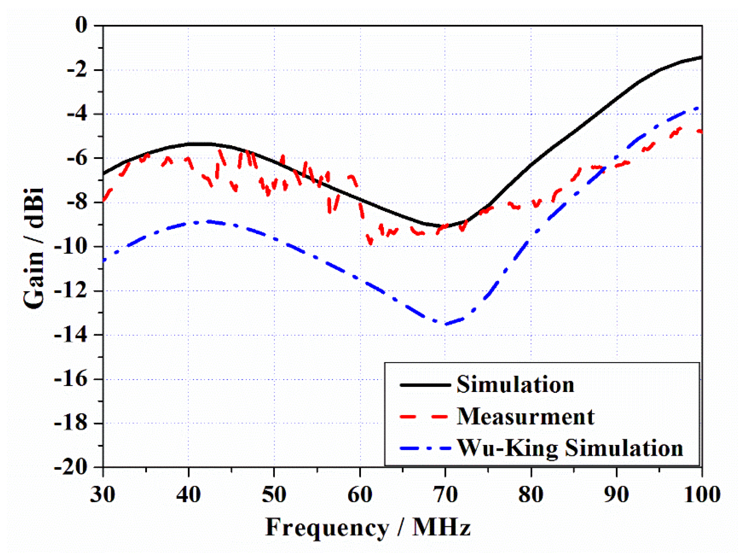
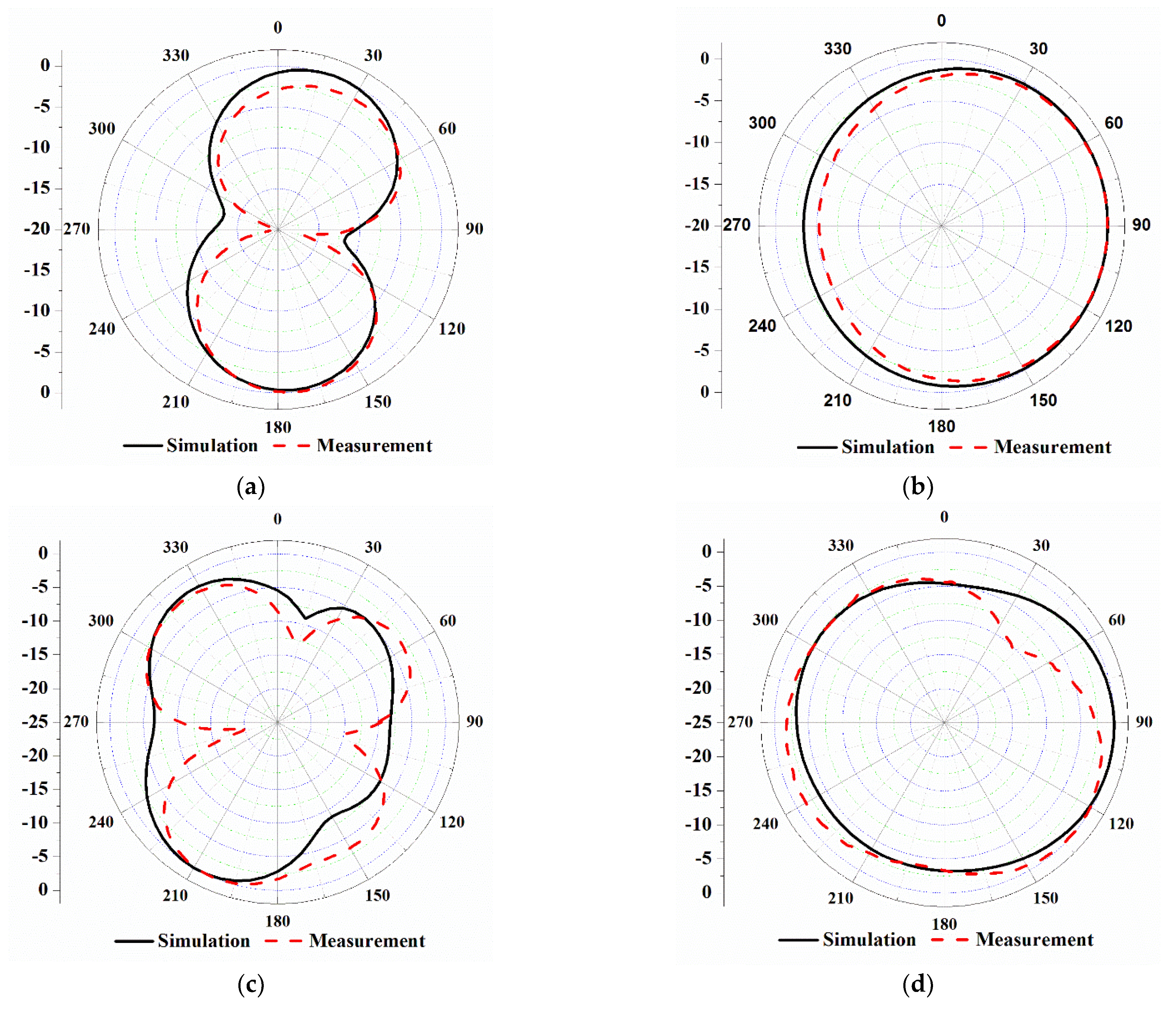
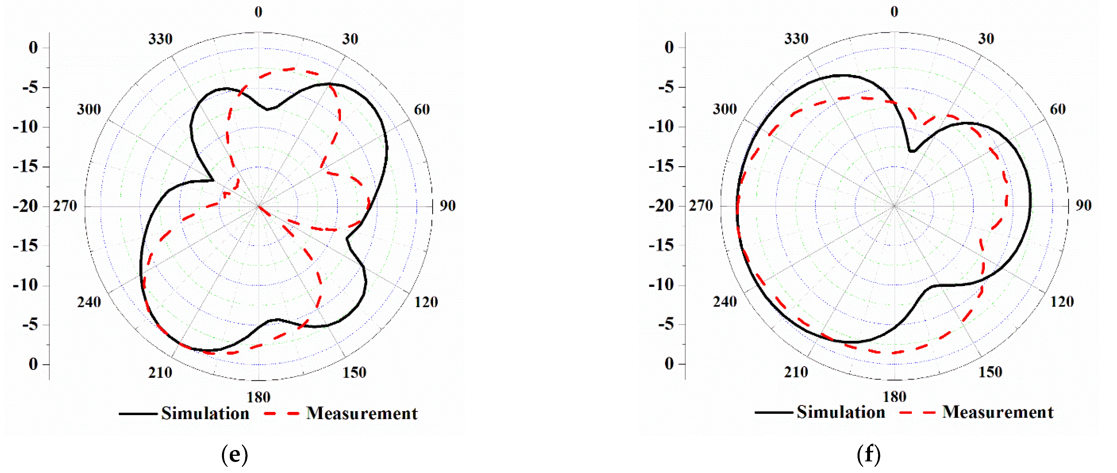
When testing the gain and pattern of the antenna, the existing microwave anechoic chamber is unable to cover the operating band, and the turntable is not suitable for installation on the huge Rover model. As a solution, a 1:4 scale model of the antenna and the Rover was designed as shown in Figure 8a, and as a result the test frequency was increased to 120–400 MHz. Figure 8b shows the test results of the antenna prototype and the scaled model. The comparison illustrates that the VSWR of the proposed antenna and its scaled-down prototype have good consistency in the trend, and the scaled model can accurately reflect the performance of the RoSPR antenna. The scaled model was tested in the standard open area test site (OATS), as shown in Figure 9. For reducing the influence of the ground, the antenna kept vertical polarization, and the zero point of the antenna orientated the ground. The definition of the Rover coordinate system is shown in Figure 2a. When the Rover is working, θ = 180 ° points to the surface of Mars, so the gain at this angle was tested. Figure 10 shows that the trend of the simulation and test realized gain is basically the same, and the gain is enhanced by 3–4 dB compared with the traditional Wu–King profile. Figure 11 compares the simulated and measured patterns. The fluctuation of the test result in the 30–60 MHz band is obvious, and the gain in the 70–90 MHz band tends to be smooth. The differences between the simulated and measured curves gradually increase, which is proportional to the frequency. This discrepancy is mainly caused for the following reasons: (a) the insertion loss of the feed transformer is 0.5 dB; (b) the ripple of the gain related to reflection of the OATS’s metal ground; and (c) the pattern deflects in the high frequency band, and the change reaches 2–2.5 dB at θ = 180 ° , as shown in Figure 11e. As displayed in Figure 11, the discrepancies between the simulated and measured patterns are obvious at θ = 0 ° (+Z to the Rover), and the patterns at θ = 180 ° (–Z to the Rover) are generally consistent. The testing strut is made of glass fiber composite material, with a relative dielectric constant of 4.2 and a width of 10 cm. The shielding and reflections of the strut will affect the strength of the received signal, thus changing the tested patterns. The influence of the strut is significant in the high frequency band. For a GPR system, antenna pattern is not a key parameter. The main radiation direction of the antenna is roughly toward the surface of Mars, which can meet the requirements of the system. Therefore, the monopole antenna can be applied to the RoSPR.
5. Experimental Validation

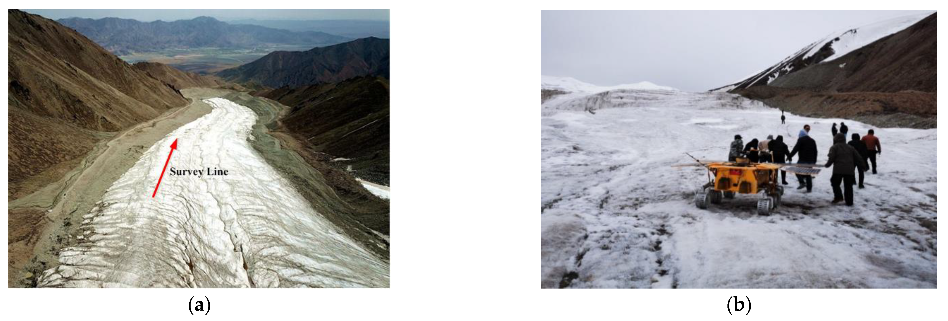
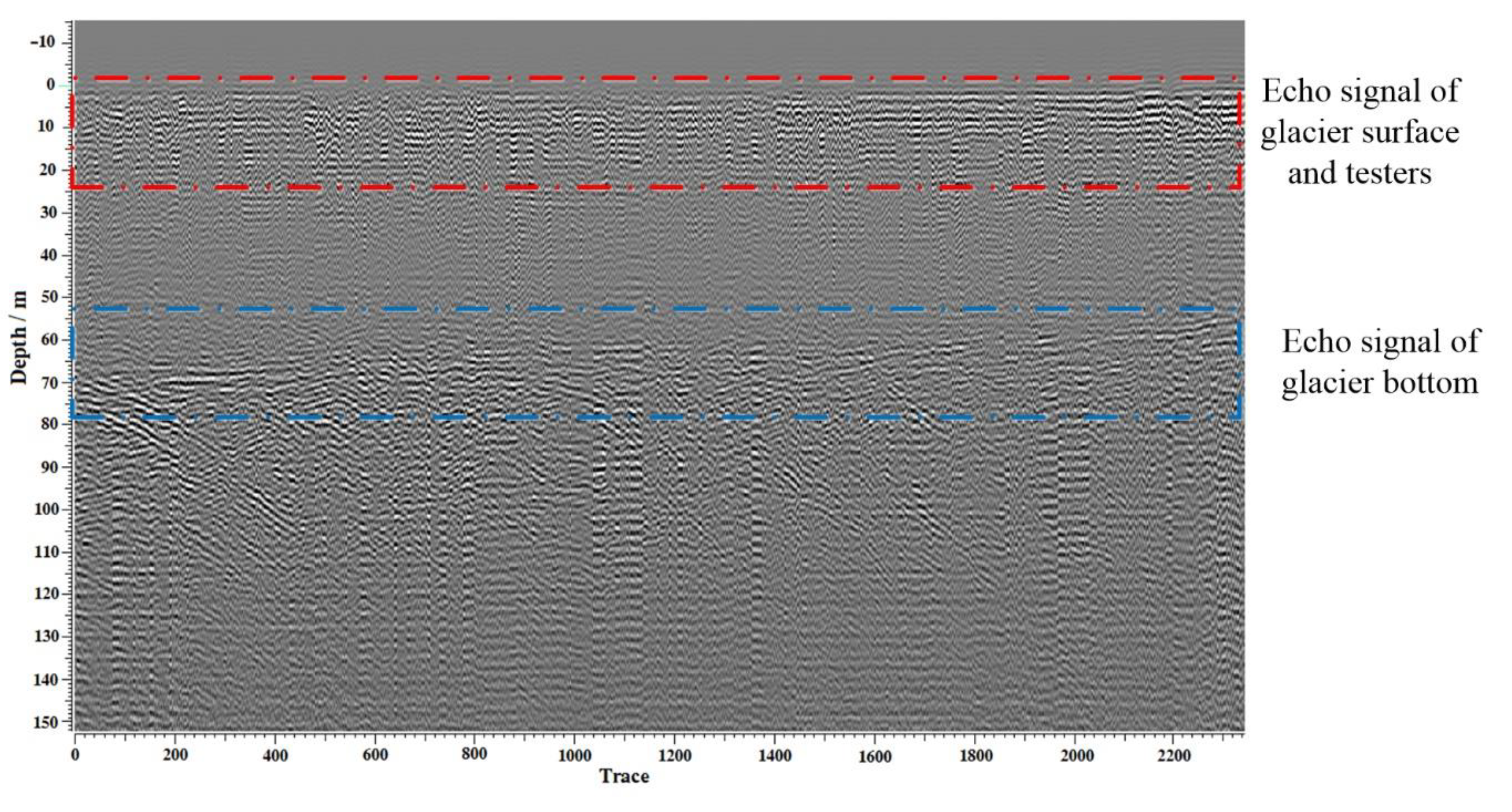
The validation experiments were conducted on Touming-Mengke glacier No.29 in Gansu Province, China, to test the effectiveness of the antenna as well as the detection capability of the RoSPR. The test location is at an altitude of 4620 m, and the path and site of the test are shown in Figure 12. Through the experiment, the B-scan image on the test path was obtained (see Figure 13). According to the test by a dielectric probe kit (Key Sight 85070E), the relative permittivity of the glacier was tested to be 3.2. The verification result shows two clear interfaces caused by the reflection of the ice surface at the depth of 0 m and the reflection of bedrock at the bottom of the glacier at the depth of 60–70 m. The echoes at the 0–20 m depth are cluttered, which are the results of multiple reflections and the movement of the testers, as shown in Figure 12b. At the depth of 20–60 m, there is no sharp echo signal in the B-scan image. We can conclude that the glacier has no obvious layered structure at this depth. The bedrock reflection at the bottom of the glacier is shown at the second interface. With the extension of the survey line from high altitude to low altitude, the depth of the glacier becomes shallow from 70 m to 60 m, which is basically consistent with the observation results of the glacier. Due to glacier movement, a mixed layer of ice and rock will be formed at the interface between the glacier and bedrock, so a large number of clutter echoes are displayed. These signals show the detailed structures of the glacier bottom, but these structures are difficult to clearly explain and verify. This phenomenon also exists in other glacier exploration [30].

6. Discussion

The proposed high-reliability UWB monopole antenna is suitable for subsurface targets and layered structure detection in harsh environments, especially for deep space exploration such as Lunar exploration, Mars exploration and asteroid exploration, because the dielectric loss is usually low in deep space exploration. Due to the resistance loading, the gain of the antenna is relatively low, but it can work in harsh environments for a long term. Therefore, it is of great significance in the field of planetary and lunar subsurface exploration.

7. Conclusions

In this study, a highly reliable UWB monopole antenna operating in the VHF band has been designed to detect the subsurface structures of Mars. Through the integrated design with the Rover, the antenna length is significantly reduced to 0.13 λ of the lowest operating frequency. An improved method based on the Wu–King profile is proposed in the design. This method can not only achieve more than 100% impedance bandwidth, but also increase the gain by 3–4 dB compared with the traditional Wu–King profile. At the same time, the reliability of the antenna is enhanced by using the planar embedded resistance and the optimized structure design. Therefore, it can adapt to the requirements of the launch and landing and long-term work on Mars. Through the verification test on the glacier, it is concluded that the antenna is suitable for detecting subsurface layered structures and targets. In the near future, TW-1 RoSPR data will be widely available via the Data Publishing and Information Service System of China’s Mars Exploration Program.

Author Contributions

Conceptualization, W.L., Y.J. and B.Z.; methodology W.L., Y.J. and G.F.; data curation, Y.L., W.L. and S.S.; formal analysis, W.L. and C.T.; validation, Y.L., S.S. and W.L.; software, Y.L. and S.S.; writing—original draft preparation, W.L.; writing—review and editing, Y.J. and Y.L.; visualization, W.L.; supervision, B.Z.; project administration, G.F.; funding acquisition, G.F. All authors have read and agreed to the published version of the manuscript.

Funding

This research was funded by the National Natural Science Foundation of China, grant number: 11941003.

Data Availability Statement

There is no more supporting data in this stage. In the near future, scientific data of RoSPR will be widely available via the Data Publishing and Information Service System of China’s Mars Exploration Program (http://moon.bao.ac.cn, accessed on 14 February 2021).

Acknowledgments

The authors acknowledge the support from the China National Space Administration. We thank the Ground Applications System of Lunar and Deep Space Exploration, National Astronomical Observatories, Chinese Academy of Science, for their efficient help in the experimental verification.

Conflicts of Interest

The authors declare no conflict of interest.

References

  1. Wan, W.X.; Wang, C.; Li, C.L.; Wei, Y.; Liu, J.J. The payloads of planetary physics research onboard china’s first mars mission(tianwen-1). Earth Planet. Phys. 2020, 4, 331–332. [Google Scholar] [CrossRef]
  2. Fang, G.; Pipan, M. Designing of A Low Frequency Ultra-wideband (UWB) Antenna and Its Application in Ground Penetrating Radar (GPR) System. In Proceedings of the Tenth International Conference on Grounds Penetrating Radar, 2004. GPR 2004, Delft, The Netherlands, 21–24 June 2004. [Google Scholar]
  3. Gall, A.L.; Ciarletti, V.; Berthelier, J.; Reineix, A.; Guiffaut, C.; Ney, R.; Dolon, F.; Bonaime, S. An Imaging HF GPR Using Stationary Antennas: Experimental Validation over the Antarctic Ice Sheet. IEEE Trans. Geosci. Remote Sens. 2008, 46, 3975–3986. [Google Scholar] [CrossRef]
  4. Abouelnaga, T.G.; Abdallah, E.A.F. Two in one VHF-conical monopole antenna for GPR application. In Proceedings of the 2014 IEEE Radar Conference, Cincinnati, OH, USA, 19–23 May 2014. [Google Scholar]
  5. Tan, A.E.C.; Jhamb, K.; Rambabu, K. Design of Transverse Electromagnetic Horn for Concrete Penetrating Ultrawideband Radar. IEEE Trans. Antenna Propag. 2012, 60, 1736–1743. [Google Scholar] [CrossRef]
  6. Rittiplang, A.; Phasukkit, P. 1-tx/5-rx through-wall UWB switched-antenna-array radar for detecting stationary humans. Sensors 2020, 20, 6828. [Google Scholar] [CrossRef] [PubMed]
  7. Gamec, J.; Repko, M.; Gamcová, M.; Gladišová, I.; Kurdel, P.; Nekrasov, A.; Fidge, C. Low Profile Sinuous Slot Antenna for UWB Sensor Networks. Electronics 2019, 8, 127. [Google Scholar] [CrossRef] [Green Version]
  8. Nayak, R.; Maiti, S.; Patra, S.K. Design and Simulation of Compact UWB Bow-tie Antenna with Reduced End-fire Reflections for GPR Applications. In Proceedings of the IEEE international Conference on Wireless Communications Signal Processing and Networking (WiSPNET), Chennai, India, 23–28 March 2016. [Google Scholar]
  9. Ajith, K.K.; Bhattacharya, A. Improved ultra-wide bandwidth bow-tie antenna with metamaterial lens for GPR applications. In Proceedings of the 15th International Conference on Ground Penetrating Radar (GPR), Brussels, Belgium, 30 June–4 July 2014; pp. 739–744. [Google Scholar]
  10. Ranasinghe, H.M.P.B.; Senanayake, S.M.P.; Senarathne, U.I.P.; Gunawardena, A.U.A.W.; Uduwawala, D.N. Design of a low cost cavity backed wideband bow-tie antenna for ground penetrating radar systems. In Proceedings of the 2013 IEEE 8th International Conference on Industrial and Information Systems, Peradeniya, Sri Lanka, 17–20 December 2013; pp. 370–375. [Google Scholar]
  11. Kwon, O.H.; Park, W.B.; Yun, J.; Lim, H.J.; Hwang, K.C. A Low-Profile HF Meandered Dipole Antenna with a Ferrite-Loaded Artificial Magnetic Conductor. Appl. Sci. 2021, 11, 2237. [Google Scholar] [CrossRef]
  12. Lee, K.H.; Chen, C.C.; Teixeira, F.L.; Lee, R. Modeling and investigation of a geometrically complex UWB GPR antenna using FDTD. IEEE Trans. Antennas Propag. 2004, 52, 1983–1991. [Google Scholar] [CrossRef]
  13. Ahmed, A.; Zhang, Y.; Burns, D.; Huston, D.; Xia, T. Design of UWB Antenna for Air-Coupled Impulse Ground-Penetrating Radar. IEEE Geosci. Remote Sens. Lett. 2016, 13, 92–96. [Google Scholar] [CrossRef]
  14. Edemsky, D.; Popov, A.; Prokopovich, I.; Garbatsevich, V. Airborne Ground Penetrating Radar, Field Test. Remote Sens. 2021, 13, 667. [Google Scholar] [CrossRef]
  15. Cao, P.; Huang, Y.; Zhang, J. A UWB monopole antenna for GPR application. In Proceedings of the 2012 6th European Conference on Antennas and Propagation (EUCAP), Prague, Czech Republic, 26–30 March 2012; pp. 2837–2840. [Google Scholar]
  16. Pennock, S.R.; Jenks, C.H.J. UWB shielded teardrop monopole antenna for GPR and communications. In Proceedings of the 2017 IEEE-APS Topical Conference on Antennas and Propagation in Wireless Communications (APWC), Verona, Italy, 11–15 September 2017; pp. 288–291. [Google Scholar]
  17. Martínez-Lozano, A.; Blanco-Angulo, C.; García-Martínez, H.; Gutiérrez-Mazón, R.; Torregrosa-Penalva, G.; Ávila-Navarro, E.; Sabater-Navarro, J.M. UWB-Printed Rectangular-Based Monopole Antenna for Biological Tissue Analysis. Electronics 2021, 10, 304. [Google Scholar] [CrossRef]
  18. Cai, L. An On-Glass Optically Transparent Monopole Antenna with Ultrawide Bandwidth for Solar Energy Harvesting. Electronics 2019, 8, 916. [Google Scholar] [CrossRef] [Green Version]
  19. Jordan, R.; Picardi, G.; Plaut, J.; Wheeler, K.; Kirchner, D.; Safaeinili, A.; Johnson, W.; Seu, R.; Calabrese, D.; Zampolini, E.; et al. The Mars Express MARSIS Sounder Instrument. Planet. Space Sci. 2009, 57, 1975–1986. [Google Scholar] [CrossRef]
  20. Biccari, D.; Picardi, G.; Seu, R. Mars high resolution Shallow Radar (SHARAD) for the MRO 2005 mission. In Proceedings of the IEEE International Geoscience and Remote Sensing Symposium, Toronto, ON, Canada, 24–28 June 2002. [Google Scholar]
  21. Croci, R.; Fois, F.; Calabrese, D.; Zampolini, E.M.; Seu, R.; Picardi, G.; Flamini, E. SHARAD Design and Operation. In Proceedings of the 2007 IEEE International Geoscience and Remote Sensing Symposium, Barcelona, Spain, 23–28 July 2007. [Google Scholar]
  22. Wu, T.; King, R. The Cylindrical Antenna with Nonreflecting Resistive Loading. IEEE Trans. Antennas Propag. 1965, 13, 369–373. [Google Scholar] [CrossRef] [Green Version]
  23. Ersch, R. Transmission-line transformers. IEEE Trans. Microw. Theory Tech. 1981, 29, 327–331. [Google Scholar]
  24. Kim, K.; Scott, W.R., Jr. A Resistive Linear Antenna for Ground-penetrating Radars. In Proceedings of the Detection and Remediation Technologies for Mines and Minelike Targets IX, Orlando, FL, USA, 21 September 2004; Volume 5415. [Google Scholar]
  25. Lee, D. A Compact Resistively-loaded Dipole Antenna Feed by a Triangular Tapered Transmission Line for Imaging Applications. AEU Int. J. Electron. Commun. 2018, 88, 126–133. [Google Scholar] [CrossRef]
  26. Wu, B.; Ji, Y.; Fang, G. Analysis of GPR UWB Half-Ellipse Antennas with Different Heights of Backed Cavity above Ground. IEEE Antennas and Wirel. Propag. Lett. 2010, 9, 130–133. [Google Scholar] [CrossRef]
  27. Lee, D. Investigation of the Pulse Radiating Performance of Resistively Loaded Dipole Antennas by Manipulation of the Loading Parameter. AEU Int. J. Electron. Commun. 2019, 98, 248–258. [Google Scholar] [CrossRef]
  28. Li, H.; Li, Y. Mode Compression Method for Wideband Dipole Antenna by Dual-Point Capacitive Loadings. IEEE Trans. Antennas Propag. 2020, 68, 6424–6428. [Google Scholar] [CrossRef]
  29. Montoya, T.P.; Smith, G.S. A Study of Pulse Radiation from Several Broad-Band Loaded Monopoles. IEEE Trans. Antennas Propag. 1996, 44, 1172–1182. [Google Scholar] [CrossRef]
  30. Rutishauser, A.; Maurer, H.; Bauder, A. Helicopter-borne ground-penetrating radar investigations on temperate alpine glaciers: A comparison of different systems and their abilities for bedrock mapping. Geophysics 2016, 81, 119–129. [Google Scholar] [CrossRef]
Figure 1. Geometry of the antenna. (a) Antenna radiation surface and resistance distribution. (b) Antenna arm structure. The structural parameters of the antenna are as follows: L = 1350 mm, l = 193 mm, w = 10 mm and D = 12 mm.
Electronics 10 00682 g001
Figure 2. Positions of the antennas on the Rover. (a) Deployment status. (b) Folded status.
Electronics 10 00682 g002
Figure 3. Structure of embedded resistance.
Electronics 10 00682 g003
Figure 4. Deployment and folding mechanism. (a) Deployment status. (b) Folded status.
Electronics 10 00682 g004
Figure 5. Mechanical test status. (a) Distribution of response points. (b) X-axis vibration test status.
Electronics 10 00682 g005
Figure 6. Thermal test preparation. The transmitting antenna is deployed and the receiving antenna is folded.
Electronics 10 00682 g006
Figure 7. Voltage standing wave ratio (VSWR) of the antenna.
Electronics 10 00682 g007
Figure 8. Structure and test of the scaled model. (a) Scaled model of the antenna and Rover. (b) VSWR comparison between prototype and scaled model.
Electronics 10 00682 g008
Figure 9. Gain test state of the scaled model.
Electronics 10 00682 g009
Figure 10. Comparison of realized gains between simulation and measurement.
Electronics 10 00682 g010
Figure 11. Simulated (solid line) and measured (dashed line) radiation patterns of the antenna. (a) E-plane @ 30 MHz. (b) H-plane @ 30 MHz. (c) E-plane @ 60 MHz. (d) H-plane @ 60 MHz. (e) E-plane @ 90 MHz. (f) H-plane @ 90 MHz.
Electronics 10 00682 g011aElectronics 10 00682 g011b
Figure 12. Path and site of verification. (a) The red arrow indicates the survey line of the Mars Rover-mounted Subsurface Penetrating Radar (RoSPR) on the glacier. (b) The RoSPR is detecting the thickness of the glacier.
Electronics 10 00682 g012
Figure 13. Results of the verification test. The red dotted box shows the echoes of the surface of the glacier and the testers, and the blue dotted box shows the echoes of bedrock.
Electronics 10 00682 g013
Table 1. Power capacity of each embedded resistor.
ResistorArea/Mil2Power Capacity/W
R17.6 × 10410.5
R29.3 × 10412.8
R31.0 × 10514.0
R41.2 × 10516.7
R51.9 × 10526.4
R62.6 × 10535.4
R76.2 × 10585.6
Publisher’s Note: MDPI stays neutral with regard to jurisdictional claims in published maps and institutional affiliations.