1. Introduction
The last decades constitute an emerged expansion of the research in control quality, along with reliability of systems. Such a growth is caused by increasing complexity of systems in every branch of industry. An availability of newer and newer devices requires developments of such advanced control approaches. Especially, an Internet of Things (IoT) [
1,
2] introduces new possibilities. By connecting more devices to some clouds, it is possible to manage a process and analyze all of the data. Such solutions made it possible to develop approaches which allow to optimize the performance of systems. Constantly, a development of a Fault Diagnosis (FD) [
3,
4], as well as Fault-Tolerant Control (FTC) [
5,
6,
7], is a subject of research for researchers all over the world. Of course, there are already plenty of methodologies which can handle specific issues in their own specific manner.
The most significant and interesting problem is the one concerning the actuator, as well as sensor fault estimation. An efficient fault estimation is empowered to employ diverse FTC schemes. The goal of applying a suitable FTC scheme is to compensate the faulty sensors and actuators. As an example, some of the developments are listed, as follows: in Reference [
8], a neural network-based FTC is proposed, where Ho and Yen consider reliability and survivability of dynamic systems under unanticipated failures. Shen et al., in Reference [
9], propose another ANN-based FTC with fault alarms. A sliding mode control scheme is proposed in Reference [
10], where its feature is to reallocate the control to remaining actuators when a fault or failure occurs. On the other side, Edwards et al. propose a sliding mode estimator in Reference [
11]. Lavretsky et al. propose a robust adaptive control in Reference [
12], by consideration of dynamic systems operated in the precense of parametric uncertainties and bounded noise. In Reference [
13], a gain scheduling control is proposed by Galuppini et al. Moreover, there are also FTC approaches standing for Takagi-Sugeno-based fuzzy systems, e.g., in References [
14,
15,
16]. Of course, the problem of FD, as well as FTC, is still open, and newer approaches guaranteeing stability during the fault occurrence are going to be developed.
The vast majority of studies in FD and, as a consequence, FTC are focused to either actuator or sensor faults with the simultaneous assumption that the system is occupied only by one kind of fault [
17,
18,
19]. Of course, such an assumption stands for an unrealistic one due to the fact that both actuator and sensor faults might simultaneously affect the system. In this paper, the robust observer for descriptor systems is proposed, which is able to estimate the state, as well as actuator and sensor faults. Nevertheless, in the paper, it is assumed that a system can also be occupied by unknown input disturbances, where, to handle with such a problem, the idea is to decouple such a vector of disturbances by employing a suitable robust descriptor-based estimator. Moreover, the observer is the base for the fault-tolerant tracking control, in which the main purpose is to minimize an error between a referenced and a faulty system in the event of occurred faults, along with unknown input and external disturbances. Robust stability for both, observer and controller, is obtained by using a so-called
performance.
Consequently, the paper is organized as follows:
Section 2 describes the fault-tolerant tracking control, as well as robust observer design. Moreover, the
performance for robust stability is presented. In
Section 3, the DC servo-motor laboratory system is used to validate the correctness and performance of the proposed FTC scheme, along with the robust observer. Accordingly, the considered fault scenario contains the actuator and sensor faults, as well as unknown input and external disturbances, which simultaneously occurred in the system. Finally, the paper is concluded in
Section 4.
To make the readability of the paper more clear, the notation presented in
Table 1, i.e., symbols and variables, will be used throughout the paper.
2. Fault-Tolerant Tracking Controller Design
Let us describe the following linear system, along with an uncertainties, faults, and unknown input:
where
,
,
indicate the output, input, and state vectors, respectively. Moreover, the sensor and actuator fault vectors are defined by
and
, respectively. Furthermore,
indicates sensor fault distribution matrix, where
is satisfied. Moreover, the unknown input vector is given with
, while
D defines the unknown input distribution matrix. Finally,
and
indicate an external disturbances vectors, while
and
are the distribution matrices of these disturbances vectors.
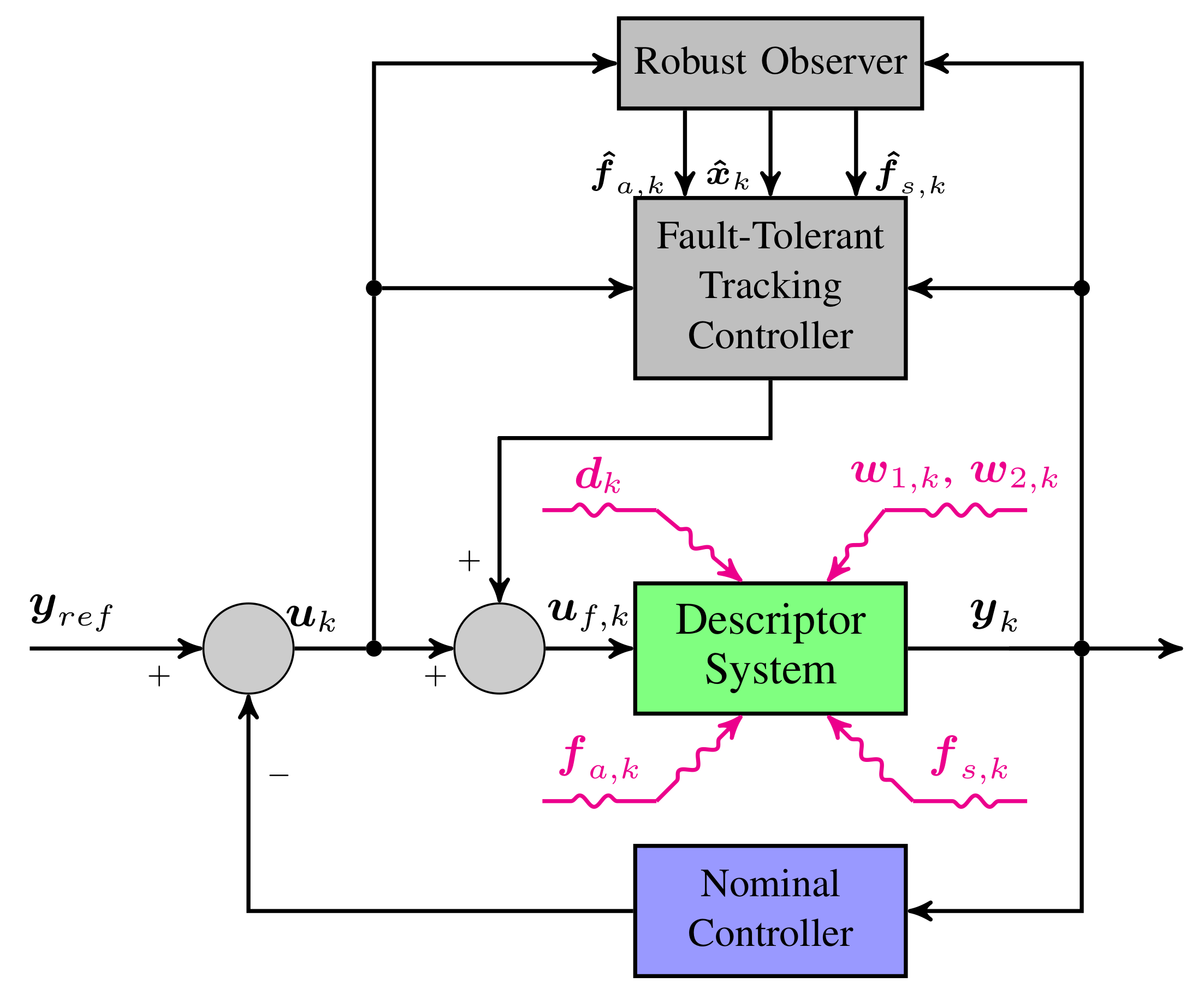
The main purpose of this paper is to achieve the tracking FTC approach capable of reducing the tracking error between the reference system
, and possibly faulty system
, which may be occupied by the actuator and sensor fault, as well as unknown input and external disturbances. Accordingly, the tracking FTC scheme is shown in
Figure 1.
The main objective of this paper is to provide the tracking FTC scheme based on robust observer in order to reduce the tracking error between the faulty system
and reference system
. Thus, the control strategy is illustrated in
Figure 1.
Indeed, since it is a common knowledge that the system may be split into actuators and process dynamics, as well as sensors, they all might be affected by faults. Of course, the system here is transformed into a descriptor one; however, this is due to the fact of an estimator structure capable for reconstructing both state, as well as sensor and actuator, faults. In this case, the system is affected by the actuator faults
and sensor faults
, as well. Moreover, unknown input disturbance
also affects the system. Besides process and measurement uncertainties,
and
influence the system, as well. So, to handle such inflows, it is proposed to employ an additional fault-tolerant tracking controller, along with a robust observer, which, together, modify the control input irrespective to the nominal controller already worked within a closed-loop, to ensure a stability of the system in case of the occurring faults and the external disturbance. Let us start from defining the reference controller without any faults and disturbances, which is already implemented in the system:
along with:
while the reference control input given as follows:
where
,
, and
indicate, respectively, the reference, state, and output vectors. Additionally, let us define the following control input for the faulty system (
1)–(
2), where the faults, along with unknown input, may occur in the system, simultaneously:
where
indicates the gain matrix for the tracking FTC controller design.
Thus, let us transform the state Equation (
1) of faulty system as follows:
where
indicate the auxiliary actuator fault vector, and
is the auxiliary matrix, with satisfied
.
Furthermore, based on (
7) with (
1), it can be easily seen that
Thus, the original fault is given as
where
signifies the pseudo inverse operator. Finally, let us transform (
7)–(
2) into the following descriptor form:
where:
Moreover, the faults, as well as state, are moved into a one state super-vector as follows:
Nevertheless, in case of very well control quality of the faulty system (
1)–(
2), it is necessary to achieve a very good estimation. Due to this fact, let us propose the following robust observer:
where the state estimate is given with
, and the internal state of the observer is defined with
. Furthermore, let
and
matrices be defined as follows:
or, in simpler form,
where (
13)–(
14) design condition is given as
Accordingly, using (
11) and (
14), let the state estimation error be calculated as follows:
Therefore, based on (
15), the state estimation error can be reduced into
Thus, in dynamics purposes, let (
10)–(
13) be substituted such that
However, from (
20), it is assumed that:
which allows removal of
and
from (
20) and (
21), respectively. Let us apply (
15) into (
21) such that
Moreover, let us define the estimator gain matrix
which allows us to rewrite (
24) into
and, in consequence, the state estimation error (
20) may be described as follows:
Thus, let be (
6) substituted into (
1) such that
where estimation
and tracking
errors are defined as follows:
and they can be calculated as
Additionally, based on (
31), it is necessary to assume that
which reduces (
31) into
Consequently, based on (
30)–(
31), the following super-vectors can be achieved:
In this way, the following equation may be obtained:
and it can be transformed into following compact form:
where:
Hence, based on (
36), it can be easily observed that eigenvalues of
depend on
and
. Due to this fact, the controller, along with an observer, can be designed separately. Accordingly, let us define the controller-based system:
along with an observer-based system:
Based on the above, let the Lyapunov function be recalled as
where
is satisfied. Thus, the stability condition may be defined by
while:
Consequently, let us establish the following theorem for the observer design:
Theorem 1. For a prescribed attenuation level μ of , the observer design problem for the system (1)–(2) is solvable if there exist and , and the following condition is satisfied: Proof. Using the stability condition (
40), it can be observed that
and, substituting (
38), the inequality can be transformed as follows:
Hence, based on
let us describe (
43) by
and rewrite it into an alternative form,
After that, let us use the Schur complement and multiply (
46) from the left and right side by
to achieve the following inequality:
Finally:
is the desired conclusion. □
It follows immediately that the observer design procedure is diminished to solve the LMI (
41) and calculate the following gain matrix:
Additionally, let us propose the following theorem for controller design:
Theorem 2. For a prescribed attenuation level of , the controller design (6) is solvable if there exist matrices , U, such that the following condition is satisfied:where . Proof. This proof follows by the same method as in
Theorem 1. Thus, based on the stability condition (
40), it can be easily seen that
and, using (
38), the inequality can be rewritten as
Thus, using
let (
53) be defined by
or, in its simpler form,
where it can be described in alternative form (
51) based on the used technique in Reference [
20] (for
Theorem 1), which proves the theorem. □
Accordingly, the controller design procedure is diminished to solve the LMI (
51) and calculate
.
3. Illustrative Example
The DC servo-motor laboratory system, illustrated in
Figure 2, is proposed to validate the performance and correctness of the described FTC scheme (see Reference [
21] for more details).
Let us start from describing the discrete-time system matrices:
where
indicates the sampling time, and it is equal to
. Additionally, the experiment time is equal to
, and the total number of samples (
k) is 1800. Moreover, the system state vector is defined as:
while
,
v, and
I signify the rotation angle, rotary speed, and current value of the DC servo-motor, respectively. Moreover, all initial conditions for the state estimate and control are equal to 0.
Additionally, the other parameters are defined in
Table 2.
Moreover, the distribution matrices for the disturbances vectors of the process and measurement uncertainties are given as follows:
To find a solution of the LMIs (
41) and (
51), and as a consequence to calculate gain matrices, a MATLAB environment by MathWorks were used, along with Yalmip and Sedumi packages. After doing this, the following gain matrices were obtained:
Additionally, to confirm the performance of the proposed FTC scheme based on a robust observer, let use define the following fault scenario:
along with the distribution matrices for the sensor fault and unknown input, respectively:
which means that the sensor fault occurred in the first state
, while the unknown input disturbance occupied the third state
I. Note that the sensor fault is designed based on sine wave, where amplitude is
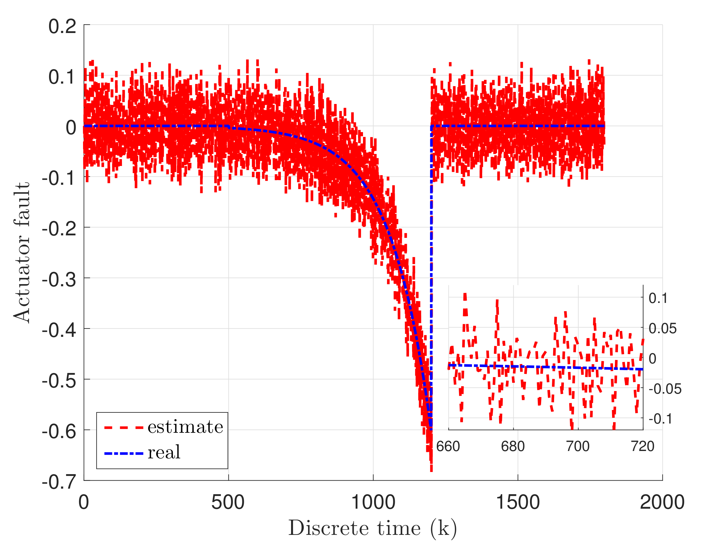
, along with period equal to 500. Moreover, the actuator fault is exponentially increasing slowly over the time, where
indicates the completely failure. Based on this fault scenario, it is easily seen that the actuator and sensor fault, as well as the unknown input disturbance, occupied the system, simultaneously.
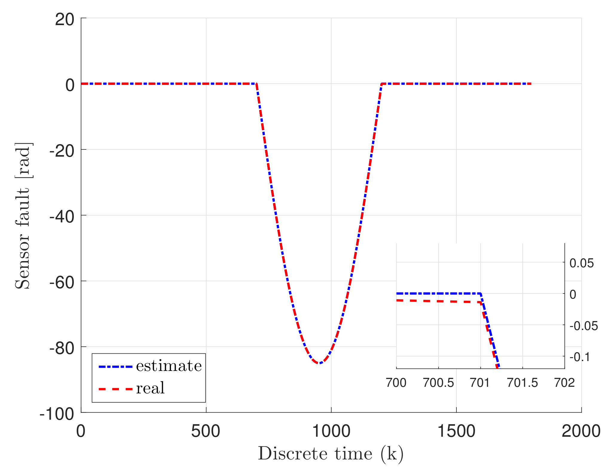
Consequently,
Figure 3 and
Figure 4 indicate the real actuator and sensor faults, given with blue dash-dotted line, as well as their estimates, illustrated with red dashed line. It can be easily observed that the faults have been reconstructed properly even of existing external disturbances. Additionally,
Figure 5 illustrates the real unknown input given with a blue solid line. The important point to note here is that the unknown input is not estimated, which makes the control process more difficult.
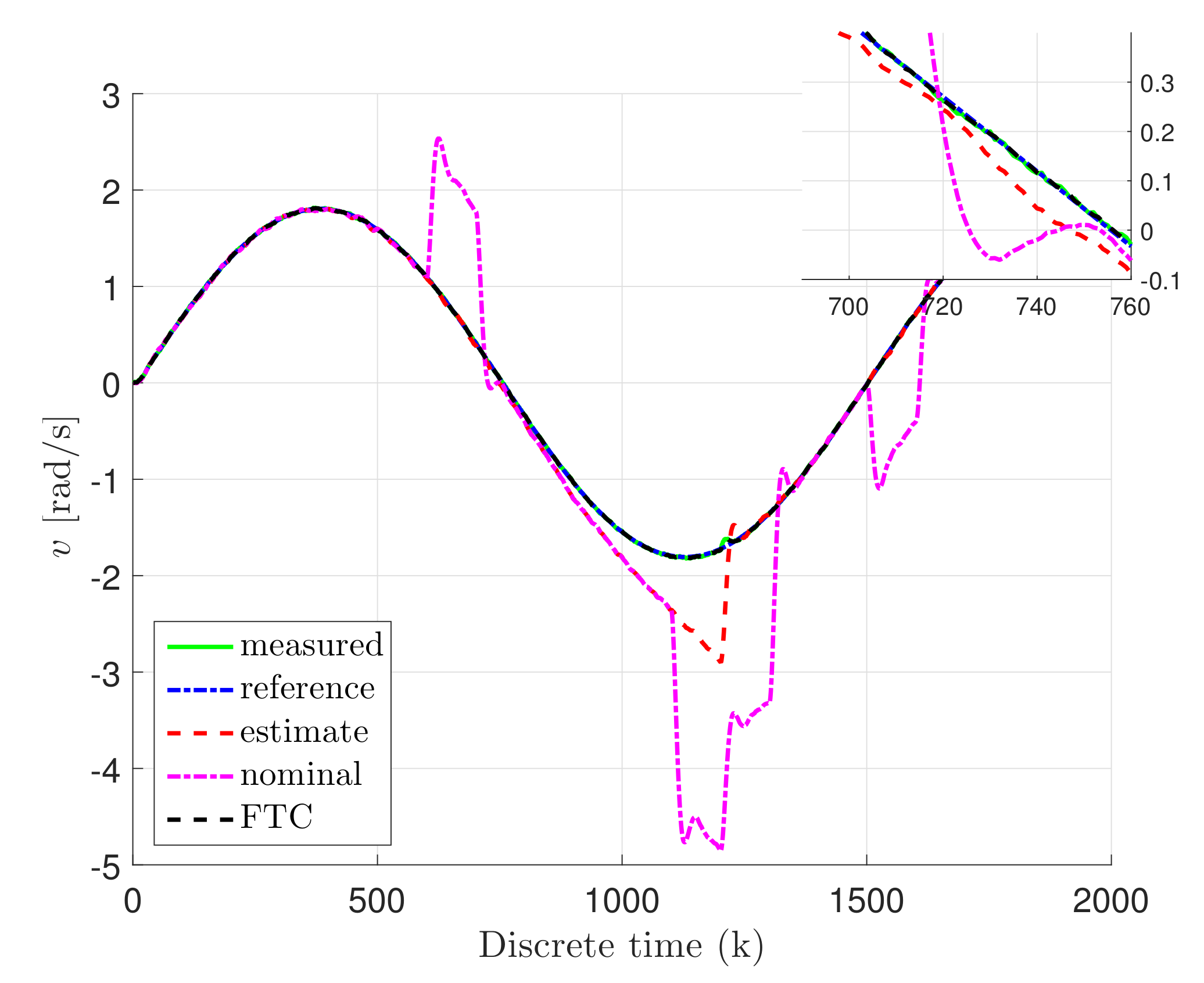
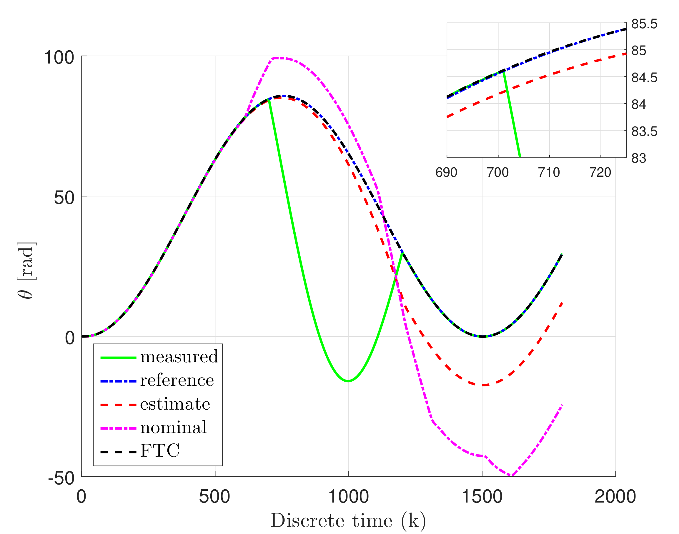
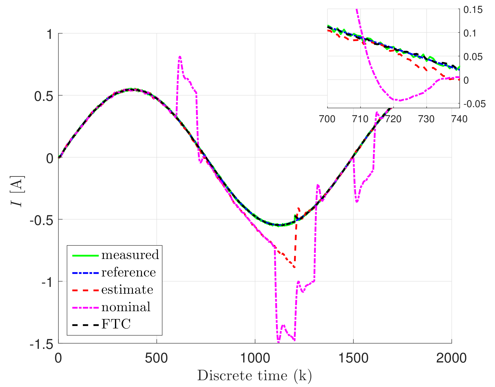
Furthermore, the following notation is used for the other figures: the reference state is given with a blue dash-dotted line, while its estimate is illustrated with red dashed line. Moreover, the measured output is depicted with a green solid line, while the nominal controller is given with a magenta dash-dotted line, and the fault tolerant controller is defined with a black dotted line.
Thus,
Figure 6,
Figure 7 and
Figure 8 show the response of the system for the states
,
v, and
I, which indicate the rotation angle, rotary speed, and current value of the DC servo-motor, respectively. It can be easily seen that estimation is following the nominal control state as long as the unknown input occurred in the system. In the other hand, the nominal controller is following the reference state until the actuator fault and unknown input occurred. Nevertheless, the FTC state is following the reference state, even the faults, as well as unknown input and external disturbances occupying the system, simultaneously. Therefore,
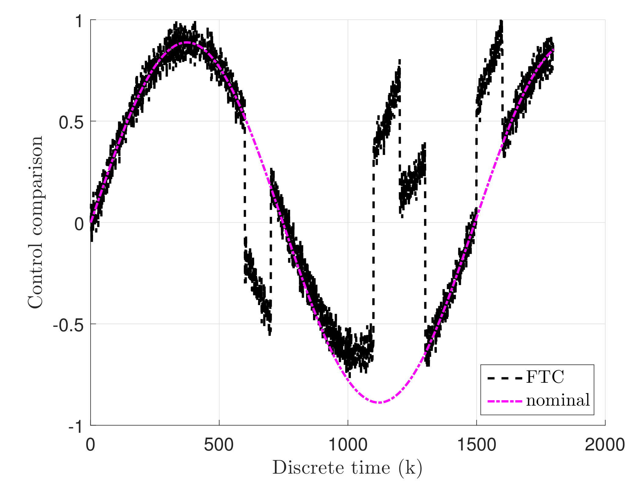
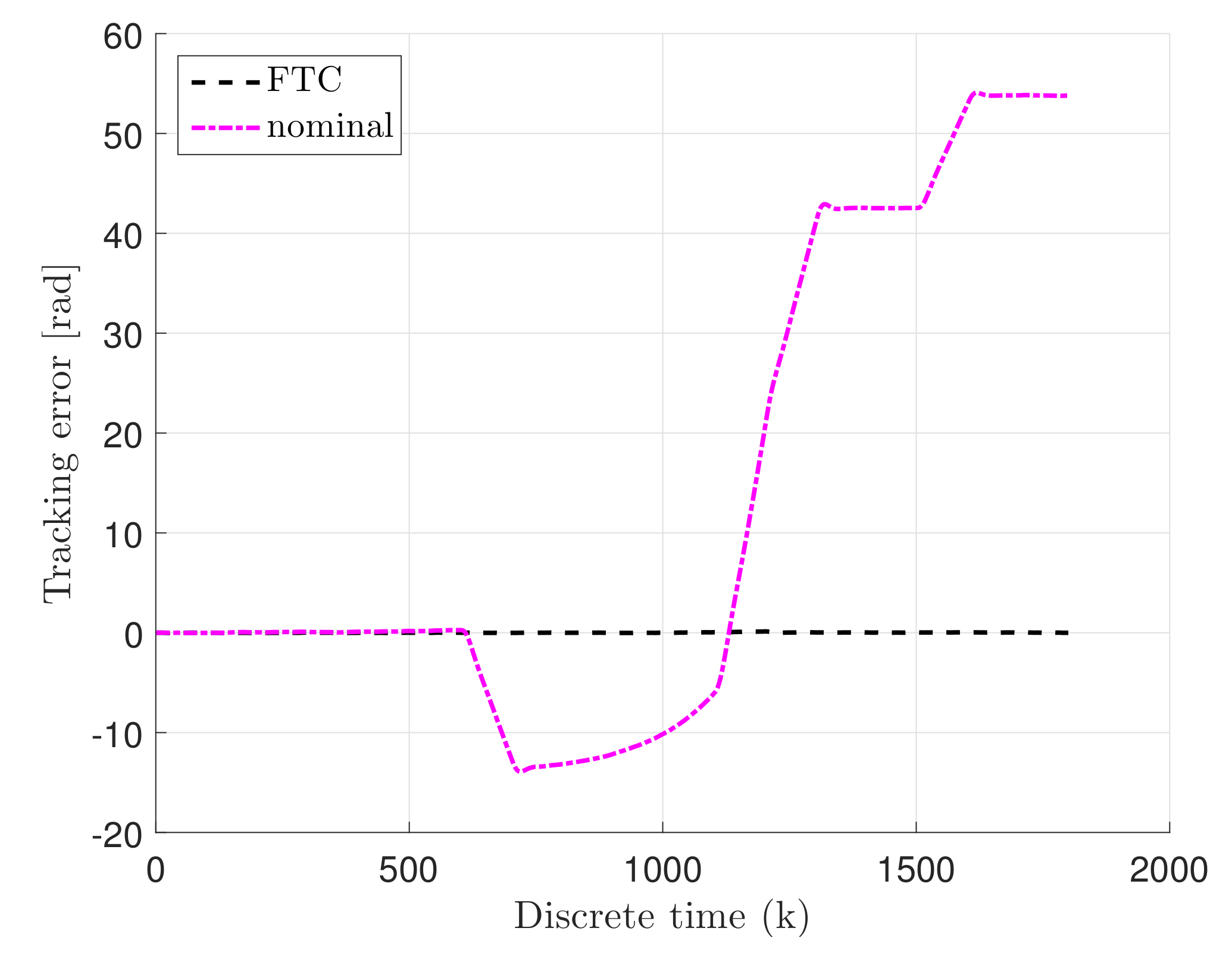
Figure 9 and
Figure 10 illustrate the control and tracking error comparison between nominal and fault-tolerant controller. Accordingly, from
Figure 9, it can be observed that FTC control input is changed due to the fact that the actuator fault and unknown input disturbance occupied the system, while the control input of nominal control is unchanged. Consequently, the tracking error of the FTC is oscillating 0, while the tracking error of the nominal controller is increasing due to the occurred actuator fault and unknown input disturbance.
4. Conclusions
The paper proposes a novel fault-tolerant tracking control scheme based on a robust observer. Moreover, this scheme was considered for the proposed linear system with the assumption that this system is possibly faulty due to the fact that it can be occupied by the unknown input, actuator, and sensor faults, as well as the external disturbances. Additionally, the robust stability for the proposed observer and FTC controller design was achieved by using the performance. Accordingly, the design procedure was reduced to solve the LMIs and calculate only two gain matrices. Finally, the laboratory DC servo-motor system was used to confirm the correctness of the proposed approach. Thus, the specific fault scenario was defined, where the system was simultaneously occupied by the actuator and sensor faults, along with the unknown input. The estimation results of the state, as well as faults, clearly confirmed correctness of the proposed observer design. Consequently, the very good estimation result provides a very good FTC control result. Accordingly, the FTC state was following the reference state with a very good accuracy, even with the occurrence of actuator and sensor faults, along with the unknown input and external disturbances. Additionally, the important thing is that the unknown input was not estimated, and, due to this fact, the observer does not correctly reconstruct the state in the event of an occurred unknown input disturbance. Nevertheless, the FTC state was properly following the reference state, even if the unknown input occupied the system.


