1. Introduction
Enhanced Mobile BroadBand (eMBB), massive-Machine Type Communications (mMTC), and Ultra-Reliable and Low-Latency Communications (URLLC) have gained the most significant interest in the fifth-generation (5G) networks era. The requirements of these generic categories of service include high data rates, a huge number of connected devices and critical reliability, and low latency. For instance, eMBB aims to offer peak data rates on the order of gigabits per second, while mMTC tends to provide connectivity for a large number of sensors with limited power capabilities [
1,
2,
3]. However, 5G does not satisfy the latency and reliability requirements for URLLC time-sensitive applications such as remote surgery. Although tactile Internet is becoming an interesting cellular application, it exhausts the network resources by a huge amount of sensors and control data [
4]. Thus, recent research envisions sixth-generation (6G) wireless communication networks to introduce new performance metrics and use cases [
5].
6G has stricter requirements, compared to 5G, such as Terabits per second (Tbps) data rates, 10 times lower latency, and sub-centimeter geo-location accuracy [
6]. Though mmWave is expected to provide data rates of Gbps in 5G, Tbps is needed for 6G applications. Hence, different frequency bands are to be explored to support higher data rates and more coverage density including terahertz (THz), and optical frequency bands [
5]. To support the strict 6G requirements and the newly introduced frequency bands, a new air interface and transmission technologies are required. Novel network architecture is essential including new physical layer (PHY) design, multiple access techniques, and heterogeneity of different spectrum bands [
7,
8,
9]. Additionally, PHY security and enhanced spectral efficiency become essential for connecting billions of sensors and devices within the Internet of Things (IoT) 6G network [
10]. In the following
Table 1, a comparison between 5G and 6G network requirements is illustrated.
Motivated by the requirement of new spectrum bands for futuristic networks, visible light communication (VLC) has gained a significantly increasing interest from academia and industry. For instance, low-complexity single sub-carrier VLC modulation schemes have been proposed including on-off-keying (OOK) and pulse position modulation (PPM) [
11]. Additionally, orthogonal frequency division multiplexing (OFDM) has been widely used for VLC systems to avoid inter-symbol interference (ISI) [
12,
13]. To satisfy the positive and real constraints on an OFDM VLC signal, unipolar real modulation schemes are introduced. From the popular techniques, DC-biased optical OFDM (DCO-OFDM) and asymmetrically clipped optical OFDM (ACO-OFDM) are the most common. However, DCO-OFDM is limited in terms of power efficiency while ACO-OFDM has less spectral efficiency [
14,
15]. Therefore, several techniques aimed at achieving better spectral efficiency such as hybrid ACO-OFDM (HACO-OFDM), layered ACO-OFDM (LACO-OFDM), enhanced ACO-OFDM (eACO-OFDM), enhanced unipolar OFDM (eU-OFDM), and spectral and energy-efficient OFDM (SEE-OFDM) [
16,
17,
18].
In
Table 2, the achievable spectral efficiencies for the most common VLC OFDM modulation techniques are highlighted.
M represents the quadrature amplitude modulation (QAM) order,
N represents the fast Fourier transform (FFT) length, and
represents the cyclic prefix length. However, achieving a higher spectral efficiency has a penalty on both power efficiency and computational complexity. For instance, DCO-OFDM offers double the spectral efficiency compared to ACO-OFDM; however, ACO-OFDM is more power-efficient than DCO-OFDM, where DCO-OFDM requires a higher DC-bias to modulate a positive-valued waveform. Another example is the HACO-OFDM which achieves the same spectral efficiency as DCO-OFDM. However, it combines both ACO-OFDM and pulse amplitude modulated discrete multitone (PAM-DMT) signals, thus a more complex transmitter and receiver design is required to generate and process both signals separately. For SEE-OFDM, the spectral efficiency is decided based on the waveform design. While SEE-OFDM can achieve a comparable spectral efficiency to DCO-OFDM, the receiver design requires pre-conditioning before FFT where reconstruction or iterative subtracting is used to eliminate intermodulation interference due to signal clipping.
Despite the decent amount of research on several VLC-OFDM modulation schemes, to the best of our knowledge, mixed-carrier communication (MCC) is the first unified transmission scheme that embeds both high- and low-speed modulation schemes within the same waveform design. The novelty about MCC is that it can offer connectivity for low- and high-end devices, simultaneously. Thus, MCC enables transmission by design to high-speed receivers based on multi-carrier OFDM, as well as limited power IoT sensors without trading off spectral efficiency. This means MCC offers simultaneous broadband access, low-rate IoT connectivity, device-free sensing, and device-based localization [
7,
19,
20]. Similar to reverse polarity optical OFDM (RPO-OFDM) [
21], MCC is built upon a pulse width modulation (PWM)-like envelope to support dimming control as well. In MCC, OFDM samples are conditioned to shape the PWM-like envelope based on the requested dimming level. Within the PWM-like envelope, beacons are embedded and modulated using single carrier modulation techniques such as PPM and phase-shift keying (PSK) to transmit the low-stream bits and localization information. A similar design to RPO-OFDM is proposed in [
22], where OFDM is reshaped in an OOK envelope to enhance the spectral efficiency of the system; however, the system does not offer dimming control compatibility or multiple services as MCC offers.
The authors first introduced MCC in [
7,
19,
20], where the concept, simulation, and experimental validation, and an interference management study among different embedded services are investigated. However, the previous research did not present the varying parameters impacting the MCC design and performance. In this manuscript, a more focused analytical framework of the MCC transmission rather than end-to-end system simulation and experimental proof-of-concept is proposed. The main contributions of this work are as follows:
The design process of the MCC transmitter and both the low-speed and high-speed receivers;
The computational complexity analysis to evaluate the effectiveness of MCC for resource-limited devices;
The derivation of the bit-error-rate (BER) formulas per embedded modulation within MCC to investigate design trade-offs and performance optimization.
The manuscript is organized as follows: in
Section 2, a detailed transmitter and receiver design is proposed, followed by an arithmetic complexity analysis in
Section 3, which is essential to define MCC advantage for low-end receivers. In
Section 4, the trade-offs between different design parameters are analyzed, including MCC SNR, as well as the individual SNR per modulation scheme at a target BER threshold. Finally, the optimized MCC design parameters are explained and MCC performance is evaluated in
Section 5.
2. Transmitter and Receiver Design
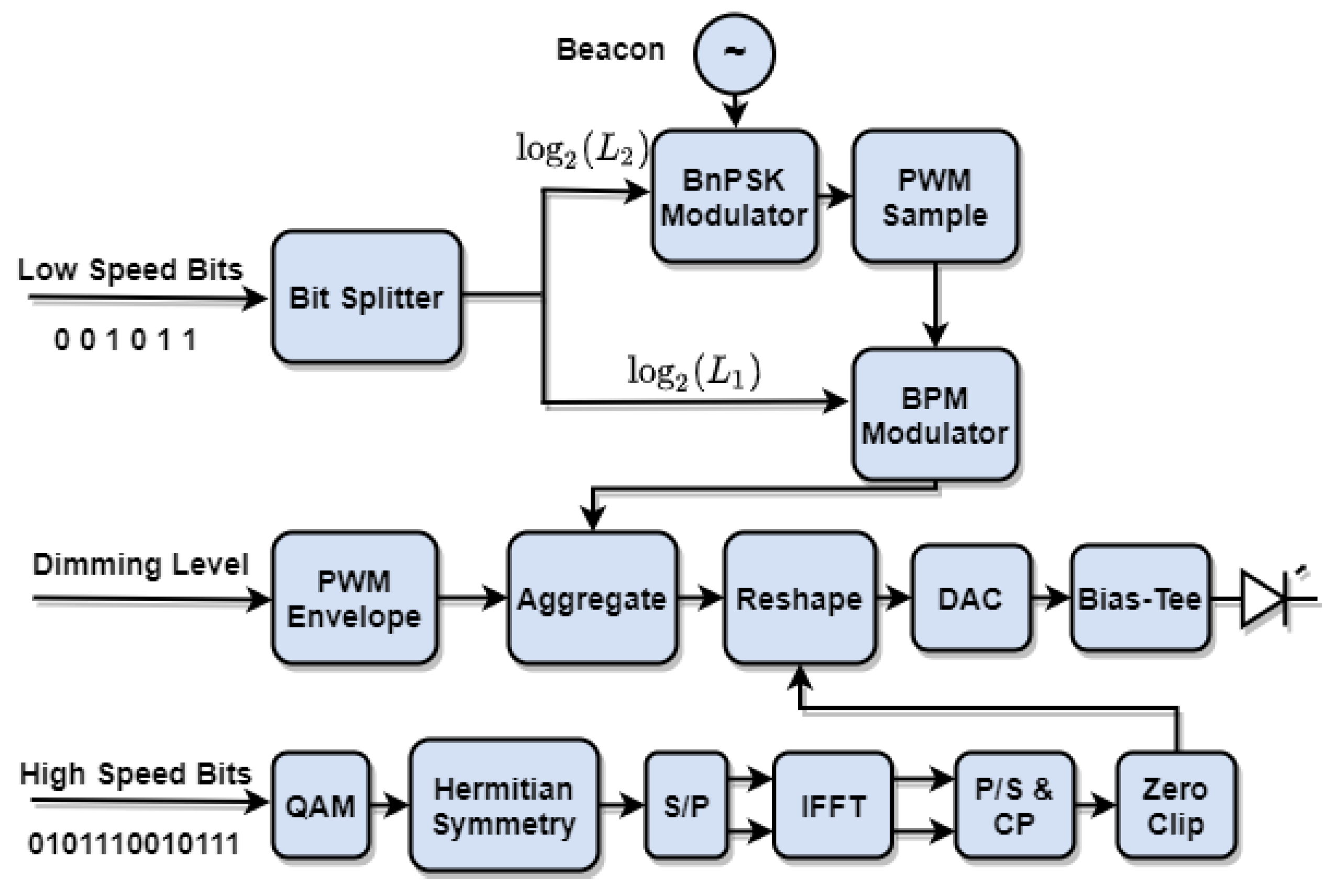
As the MCC unified waveform supports simultaneous multiple modulations, it requires a design procedure that avoids possible interference between the signal components. Additionally, MCC is composed to be supporting multiple receiver complexities. In this section, the transmitter and receiver design is explained. As shown in
Figure 1, there are two separate streams of bits to be communicating with both high- and low-speed devices. The high-speed bits are OFDM modulated, while the low-speed bits are distributed between
- beacon position modulation (
-BPM) and
- beacon phase-shift keying (
-BnPSK) modulation paths. As to comply with dimming control, MCC is designed upon a PWM-like envelope. According to Equations (
1) and (
2), a sinusoidal beacon
is
-BnPSK modulated and sampled; i.e.,
, at
intervals:
where
In Equation (
3), beacon PWM sampling is explained, where every beacon sample is represented by a specific PWM duty cycle according to Equation (
4). The
-BnPSK modulated PWM-sampled beacon is composed of reshaped ACO-OFDM samples to formulate a PWM-like envelope as shown in Equation (
4). In
Figure 1, the high-speed bits modulation path to generate ACO-OFDM samples is shown. The bits are modulated using a QAM-modulator; then, hermitian symmetry is applied before the inverse fast Fourier transform (IFFT) block to ensure a real output. All negative samples are clipped to generate positive samples only. Due to the half-wave symmetry property of ACO-OFDM, clipping the negative samples only adds clipping noise to the even sub-carriers, whereas ACO-OFDM has only the odd sub-carriers active. MCC can still be generated using different optical OFDM modulation variations:
where
and
i is the number of OFDM symbols per the on duration of the PWM cycle,
. It is essential to note that
represents negative ACO-OFDM, where positive samples are clipped rather than the negative samples being clipped as in conventional ACO-OFDM,
. Reshaping
within the on duration of the PWM duty cycle,
, allows the OFDM analog samples to be within the PWM dynamic range. Due to the half-wave symmetry property, a conventional ACO-OFDM receiver can still be used to detect both
and
within an MCC envelope [
22]. To ensure the orthogonality between OFDM sub-carriers and PWM harmonics, the minimum on duration within a PWM sample,
, of duty cycle,
, should allocate an integer number of OFDM symbols as follows:
As illustrated in
Figure 1, the beacon position is modulated within a PWM-like envelope to represent the
-BPM bits. A conventional PPM envelope follows Equation (
6), where
is a unity pulse of a duration of
and
is the PPM symbol sequence, i.e., codeword:
where
represents the envelope duration for
-PPM offering a bit rate of
and follows:
Based on Equation (
6), the
-BPM waveform is explained by replacing
in Equation (
6) by the PWM modulated beacon,
, in Equation (
3), as shown in Equation (
8):
Similar to reshaping the OFDM samples to formulate a PWM-sampled beacon in Equation (
4), the OFDM samples are reshaped to compose the dimming control PWM cycles as follows:
where
is the number of PWM cycles per an MCC envelope,
D is MCC duty cycle responsible for dimming control, and
is the number of OFDM symbols per the on duration of a PWM cycle. Finally, an MCC waveform,
that is generated by the digital-to-analog converter (DAC); to modulate a light-emitting diode (LED) after using a bias-tee for providing enough DC-bias for the LED operation, is shown in Equation (
11):
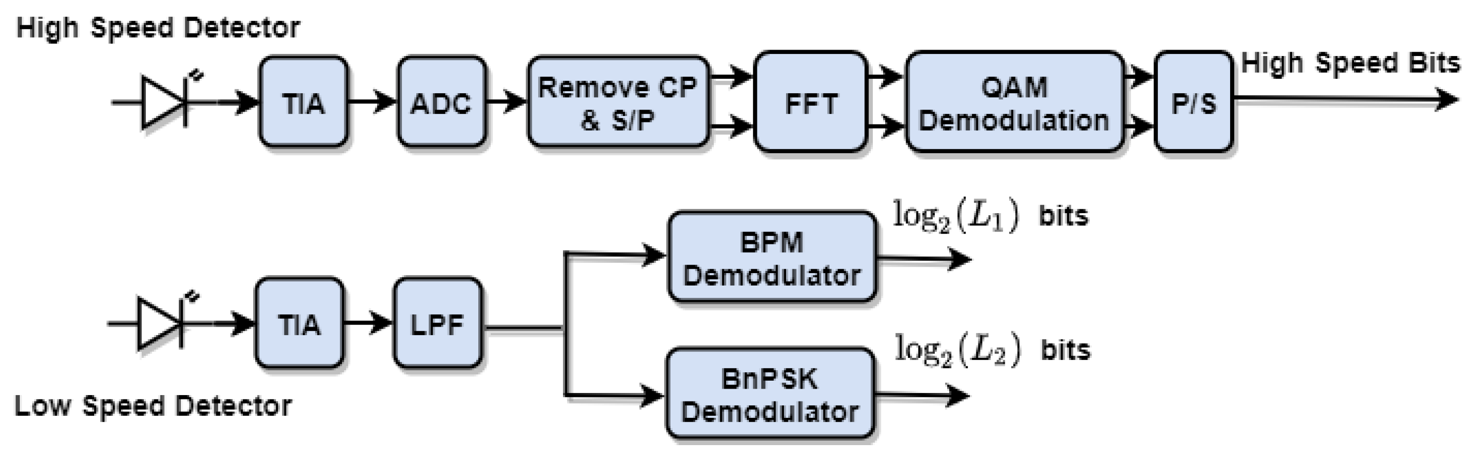
One of the main novelties about MCC is that it can support both low- and high-end receivers, simultaneously. The high-end receivers are based on conventional OFDM reception and processing. A high-speed photodetector (PD) captures the optical MCC waveform and converts the signal to the electrical domain followed by a trans-impedance amplifier (TIA). After the signal is digitized using an ADC and the cyclic prefix is removed, FFT is used to inverse the IFFT process on the transmitter side. A QAM demodulator captures the high-speed bits from the FFT complex output, taking into consideration that only odd sub-carriers are active for ACO-OFDM, as shown on the upper side of
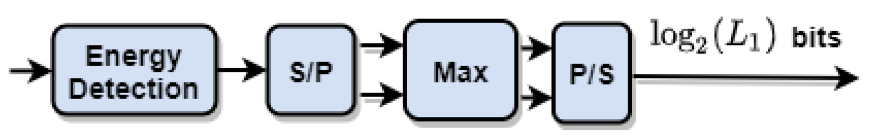
Figure 2. A simpler low-speed and low-complexity receiver is designed to capture low-speed bits on the lower side of
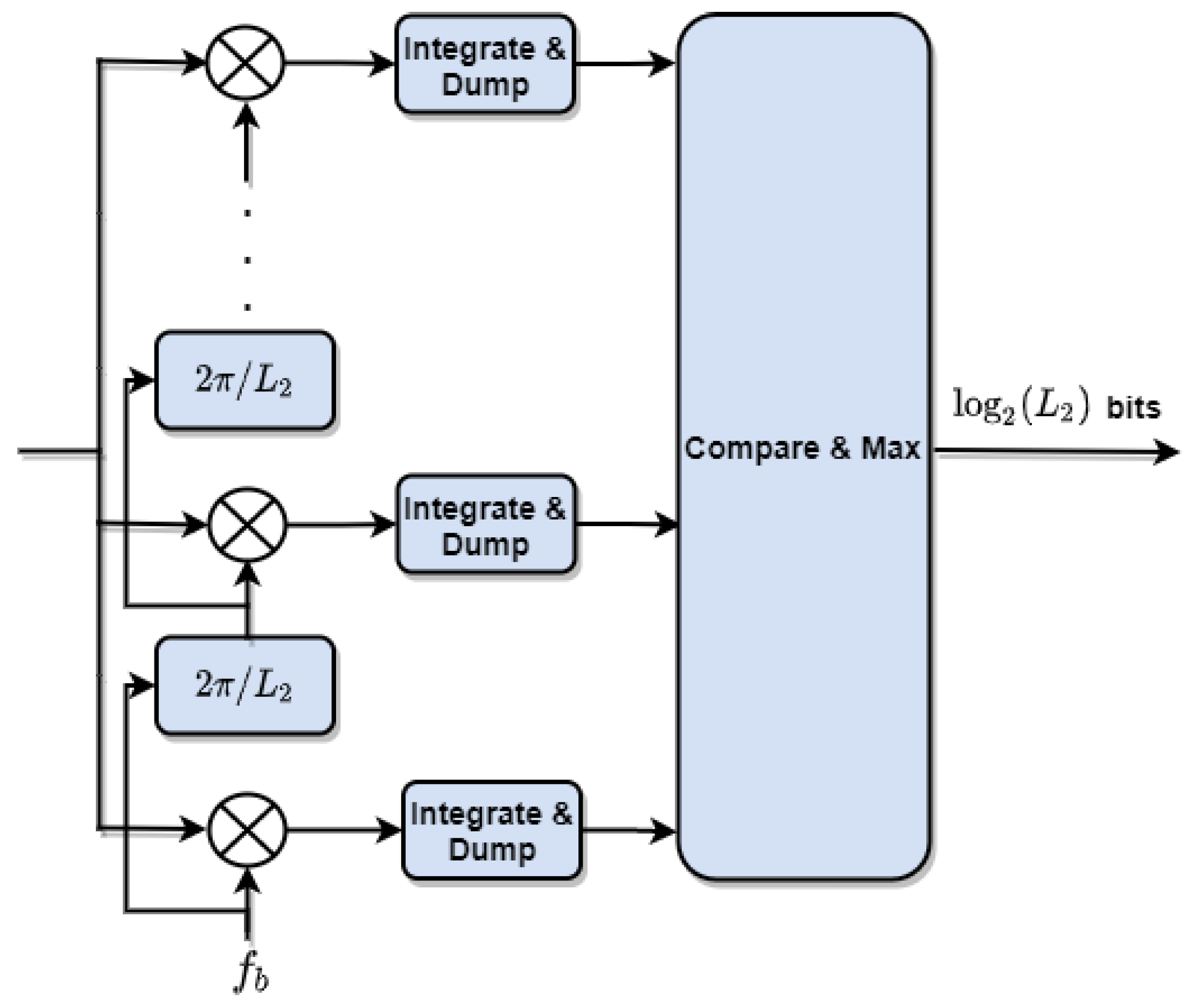
Figure 2. After the signal is captured by a PD and amplified using a TIA, the high-frequency harmonics other than the beacon frequency are filtered using a low pass filter. A low-speed PD can filter out the high frequencies, as well. The beacon phase and position within the MCC envelope are then demodulated using both BnPSK and BPM demodulators as shown in
Figure 3 and
Figure 4, respectively. A BnPSK demodulator is built upon the conventional PSK demodulator shown in [
23]. The sinusoidal waveform is multiplied
times with a sinusoidal waveform that has the same frequency but with a phase shift of
at every multiplier stage, followed by
integrator and dump blocks. The maximum output is chosen to indicate the correct phase of the input beacon, and thus represents the BnPSK bit stream. According to [
24], a PPM demodulator can be implemented using a matched filter that is matched to the beacon shape that samples every
sec and compares the output to a threshold to decide the pulse location using hard decision decoding or using a soft decision decoder and maximum likelihood (ML) detection to decide the received bits. In the proposed approach, a simpler energy detector is implemented to measure the energy of the input waveform every
sec. The maximum energy indicates the beacon location within the MCC envelope, so the BPM bits are detected:
3. Complexity Analysis
An essential feature of MCC is its unique transmitter and receiver design. As illustrated in
Figure 1, the transmitter has more blocks compared to conventional ACO-OFDM in order to transmit more bits for low-end receivers. For the ACO-OFDM waveform generation, the largest computational complexity is associated with the IFFT block. According to [
16], a radix-2 IFFT/FFT algorithm of length
N requires
complex additions,
, and
complex multiplications,
. A complex multiplication can be implemented by four real multiplications,
and two real additions,
while a complex addition includes two real additions. Therefore, an IFFT/FFT algorithm requires real multiplication operations of
and real addition operations of
. Thus, the IFFT/FFT computational complexity is dominated by
. According to Equation (2),
additions and
multiplications are required to calculate
for
beacon samples, while the arithmetic complexity of obtaining the minimum or maximum sample is
. As for the PWM-sampled BPM envelope generation based on Equation (
8),
multiplications and
additions are needed. To embed the PWM dimming control duty cycles, two additions and one multiplication are required as in Equation (
11). Subsequently, the transmitter complexity is dominated by
.
Similarly, the high-speed receiver is dominated by the FFT block arithmetic complexity,
. The interesting fact about the MCC high-end receiver is that it is being built upon the same building blocks of a conventional ACO-OFDM receiver due to the half-wave symmetry nature of ACO-OFDM, i.e.,
, as mentioned in the previous section. Thus, the output of an FFT of the NACO-OFDM symbols the same as an FFT of the original symbols [
22]. Additionally, the DC-bias only impacts the DC sub-carrier which is not actively carrying any data. As for the BPM receiver, its arithmetic complexity is dominated by the energy detector
multiplication operations and obtaining the maximum energy which requires an arithmetic complexity of
. Additionally, a BnPSK receiver requires
multiplications and integration operations, as well as obtaining the maximum value after
integrator and dump blocks. Consequently, the high-speed receiver arithmetic complexity is
, while, for the low-speed receivers, it is
. In the following
Table 3, the computational complexity of the transmitter and receiver are summarized.
4. Technology Division Multiplexing Trade-Off
MCC is designed to serve multiple technologies simultaneously in what could be considered as technology division multiplexing. One of the main challenges of embedding multiple modulation techniques within MCC is the performance trade-off per technology. This section discusses the allocated power per modulation technique and its impact on BER performance and the overall spectral efficiency, assuming a line-of-sight (LOS) flat fading VLC channel for the analysis simplicity.
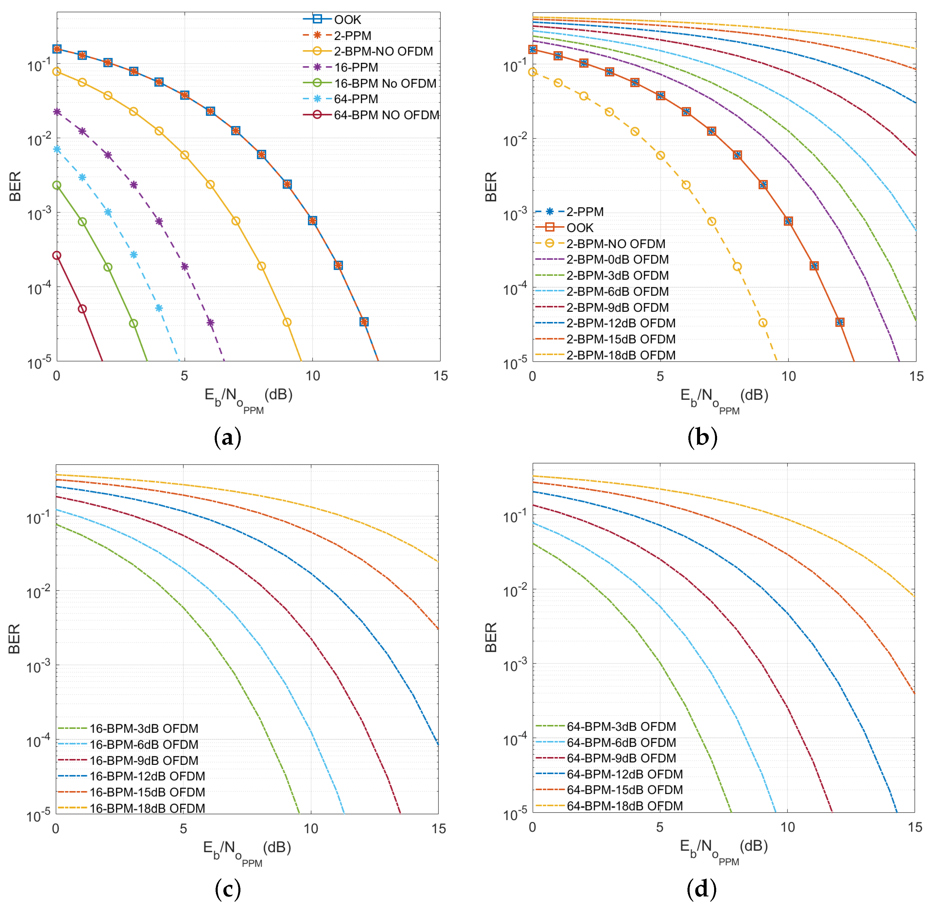
In
Figure 5, the impact of embedding an OFDM waveform within an MCC envelope on the BER performance of BPM is illustrated. Additionally, BPM BER with and without OFDM is benchmarked against OOK and PPM as shown in
Figure 5a. For fairness in BER performance comparison, both optical power
P and data rate
are unified for all PPM, BPM, and OOK modulations. Thus, the optical intensity of an OOK pulse becomes
for a duration of
; however, for
-PPM, it is
for a duration of
. As for
-BPM, the required optical intensity to maintain optical power of
P is
, where the beacon duration
is the same as
. According to [
25], assuming a high SNR, BER is dominated by the two nearest signals, BER of an AWGN channel of a double-sided power spectral density (PSD) of
, zero mean and variance of
can be approximated as
where
is the minimum Euclidean distance between any pair of valid modulation signals as shown in Equation (
13),
Accordingly, OOK and
-PPM BER behaviors are approximately performing as follows:
A PWM modulated beacon has twice the optical intensity to maintain the same average optical power
P, thus BPM has twice the
ratio. Therefore, BPM BER performance follows Equation (
16):
As shown in
Figure 5a, OOK and 2-PPM BER curves match, while
-BPM requires 3 dB less electrical power to achieve the same BER compared to
-PPM. For
-PPM and
-BPM modulation schemes, the error is confined to the symbol in which it occurs, and thus a single-slot error impacts
bits. Assuming full synchronization between the transmitter and a hard decision decoding using a threshold detector in an AWGN channel, the orthogonality between symbols increases as the PPM modulation order
increases. As a result, higher PPM modulation orders have better error performance at the same
.
Embedding an ACO-OFDM within an MCC envelope acts as a source of noise to the other modulation types including BPM. According to [
21], ACO-OFDM is accurately modeled as a Gaussian random process with zero mean and variance of
. Accordingly, there is a performance trade-off between embedded OFDM waveform and other MCC embedded modulation techniques, including BPM. Subsequently, BPM BER in Equation (
16) is adjusted to include the impact of embedded OFDM as shown in Equation (
17), where
represents the OFDM signal to interference and noise ratio including ACO-OFDM waveform clipping beyond MCC envelope as explained in [
7].
Figure 5 illustrates that BPM BER deteriorates as OFDM SINR increases. As BPM modulation order
increases, BPM BER behavior is enhanced for the same OFDM SINR and same BPM
.
In [
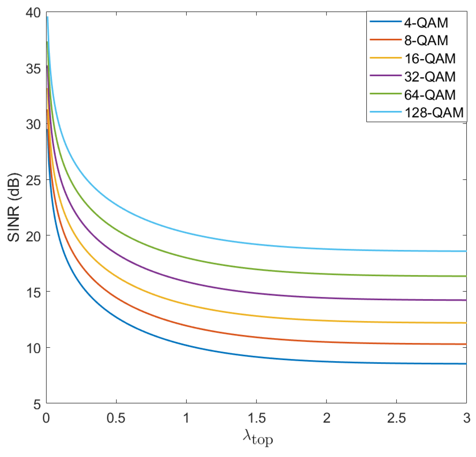
7], a detailed analysis of the optimum ACO-OFDM SINR within an MCC envelope; including the clipping impact, is discussed.
, defined as the ratio between the top optical clipping level of the ACO-OFDM waveform and its standard deviation,
, is investigated to decide the optimum OFDM modulation based on SINR. Using the analysis in [
7] to target an FEC BER threshold of
as a metric of maintaining minimum performance per embedded mixed carrier modulations,
Figure 6 illustrates the relation between
and OFDM SINR. As shown in the figure, increasing the OFDM M-QAM modulation order, requires more SINR for the same
to target the FEC BER threshold. The required SINR starts to flatten beyond
equals 1.5.
While MCC provides different modulation techniques to serve simultaneous technologies, it is essential to investigate the spectral efficiency gain,
, MCC offers. According to [
26,
27],
-PPM bandwidth
can be approximated as follows:
Thus, PPM is attractive for a range of applications where bandwidth is not of major concern as power efficiency. However, BPM bandwidth requirements are even more where BPM spectral efficiency
is constrained by the minimum PWM pulse duration
sampling the beacon as shown in Equation (
19):
To investigate the spectral efficiency gain by the low-speed modulations embedded within MCC, i.e., MCC-LS,
is considered as in Equation (
20). Without loss of generality, different types of VLC compatible OFDM modulation techniques can be incorporated; however, this analysis considers ACO-OFDM and more optical OFDM types will be considered for benchmarking in our future work. Thus, MCC overall spectral efficiency
considering M-QAM for ACO-OFDM modulation is explained by Equation (
21), assuming the number of cyclic prefix sub-carriers to be 1/4 of the total sub-carriers:
From Equations (
20) and (
21), the MCC spectral efficiency gain over conventional ACO-OFDM can be interpreted by Equation (
22),
where
and
is the ratio between
and
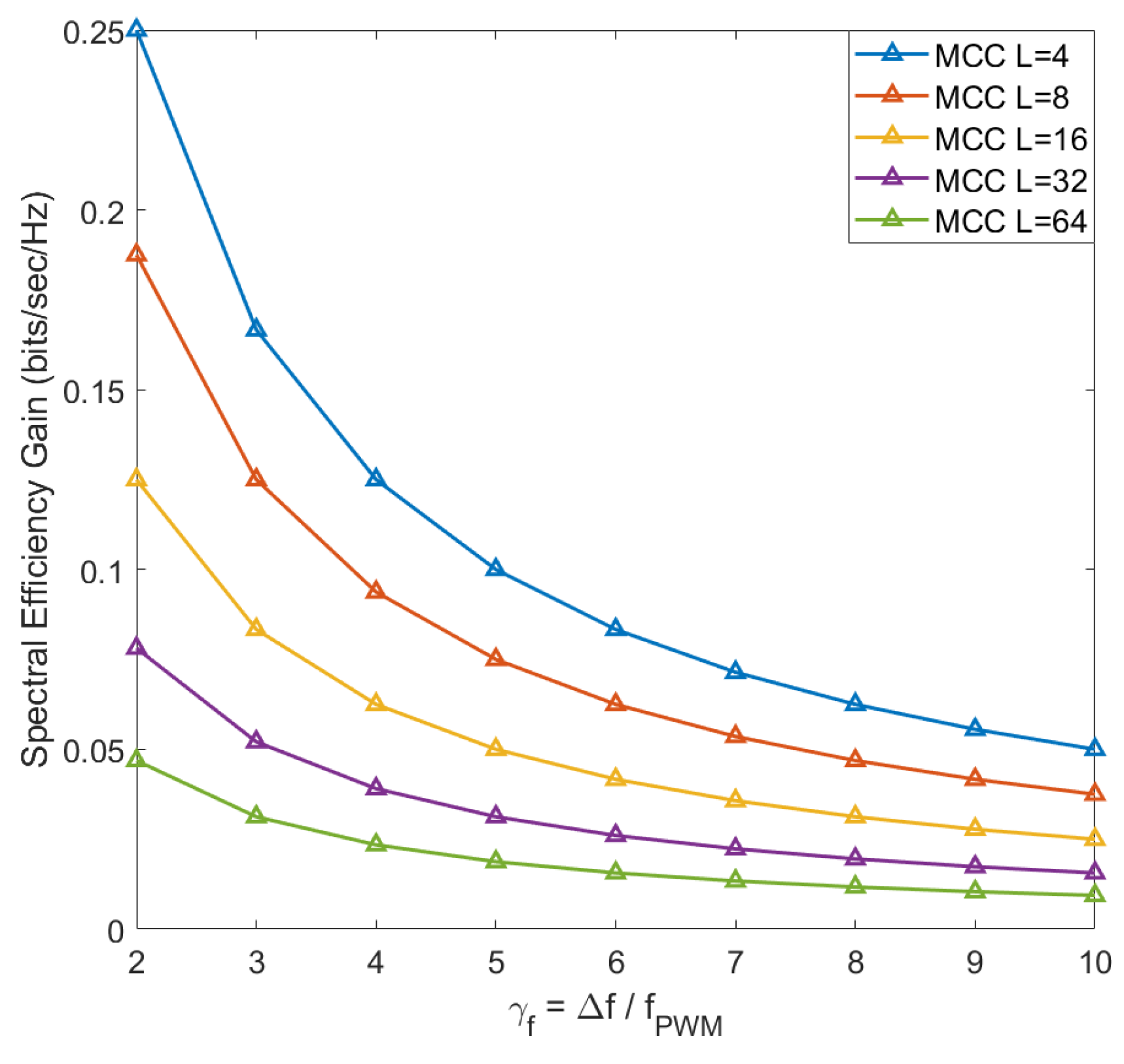
. The spectral efficiency gain is pictured in
Figure 7. The figure shows the inverse proportionality between
and the spectral efficiency gain
. As the BPM and BnPSK modulation orders
and
increase,
decreases due to the high bandwidth requirements resulting from reducing the minimum PWM pulse duration
. In the following section, the optimum spectral efficiency is analyzed to maximize the MCC spectral gain. As noticed in Equation (
16), the relation between
and
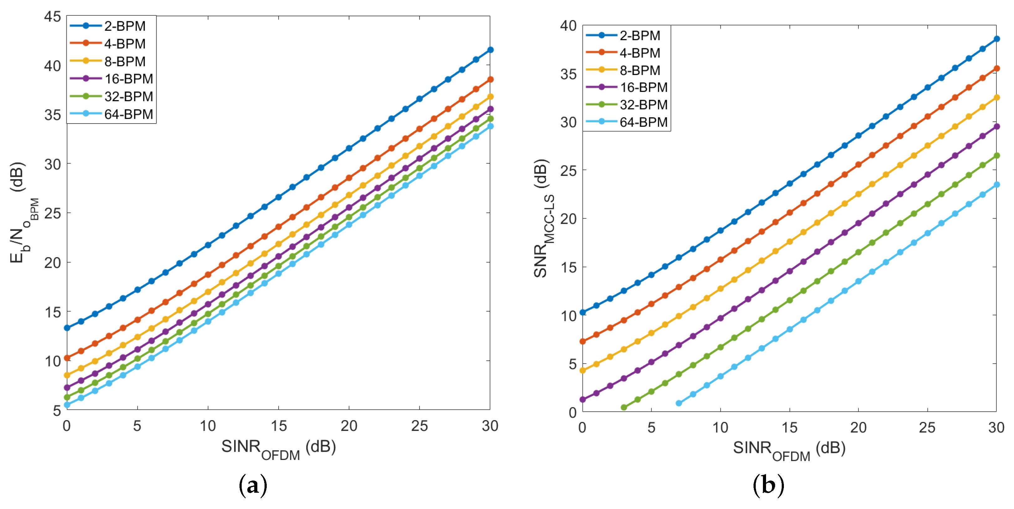
is inversely proportional. In
Figure 8a, the required BPM
to target an FEC BER threshold of
as a metric of maintaining minimum performance for BPM is illustrated with respect to the
. It is obvious that increasing the BPM modulation order reduces the power requirements for the same BER target. This is justified by the BPM high power efficiency at the cost of lower spectral efficiency. The behavior in
Figure 8a is re-plotted in
Figure 8b using Equation (
23) to illustrate the power requirements by an MCC envelope to target the FEC BER threshold for BPM:
5. Evaluation and Discussion
As shown in
Figure 7,
is inversely proportional with MCC spectral efficiency gain
. This indicates as
increases, i.e.,
decreases,
is fairly noticeable as BPM and BnPSK modulation orders increase. To maximize the spectral efficiency, an optimization problem is formulated constrained by a BER per modulation of
as follows:
The optimization problem is constrained by several constraints related to MCC design and performance. This optimization problem is defined as a nonlinear problem that is solved using the optimization toolbox by MATLAB, based on initialized values.
MCC is designed to support localization on top of communications based on the signal strength of received beacons. Thus, the envelope duration
is constrained by 150 ms to provide a reasonable advertising interval for reliable positioning accuracy for a walking person within an indoor space. This setting allows a maximum of 300 ms advertising time if one beacon is located at the beginning of an envelope while the consecutive beacon is located at the end of the following envelope. According to [
28,
29], 100–350 ms is an acceptable range for a stable indoor positioning system of a mobile object at a normal walking speed. According to [
7],
is constrained by a lower limit of 200 Hz to provide flicker-free illumination and an upper limit of
, i.e.,
, to mitigate PWM harmonics interference with OFDM sub-carriers. In addition, most commercial LEDs have limited bandwidth not exceeding 10 MHz. Additionally, to comply with minimum Nyquist sampling requirements,
has to be larger than twice
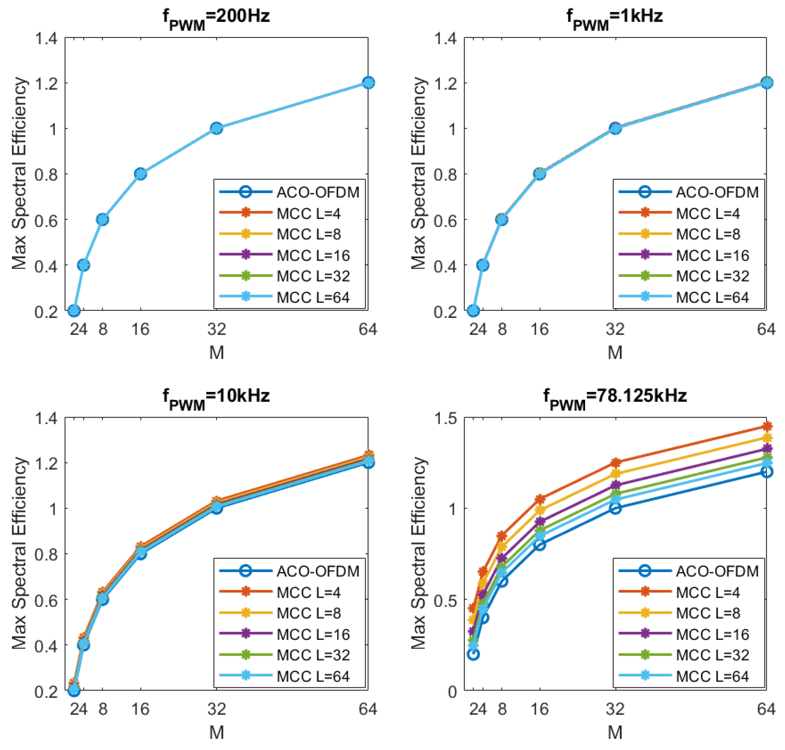
. Subsequently,
Figure 9 shows the maximum spectral efficiency obtained by MCC compared to ACO-OFDM at different PWM frequencies, targeting the FEC BER threshold for all modulation techniques. At a lower PWM frequency range of 200 Hz–1 kHz, MCC does not show an obvious enhancement in terms of achievable maximum spectral efficiency compared to ACO-OFDM. As
increases, MCC shows a better performance which is more obvious at the upper PWM frequency limit of 78.125 kHz, where MCC with L = 4 offers the highest maximum spectral efficiency compared to higher BPM and BnPSK modulation orders. In
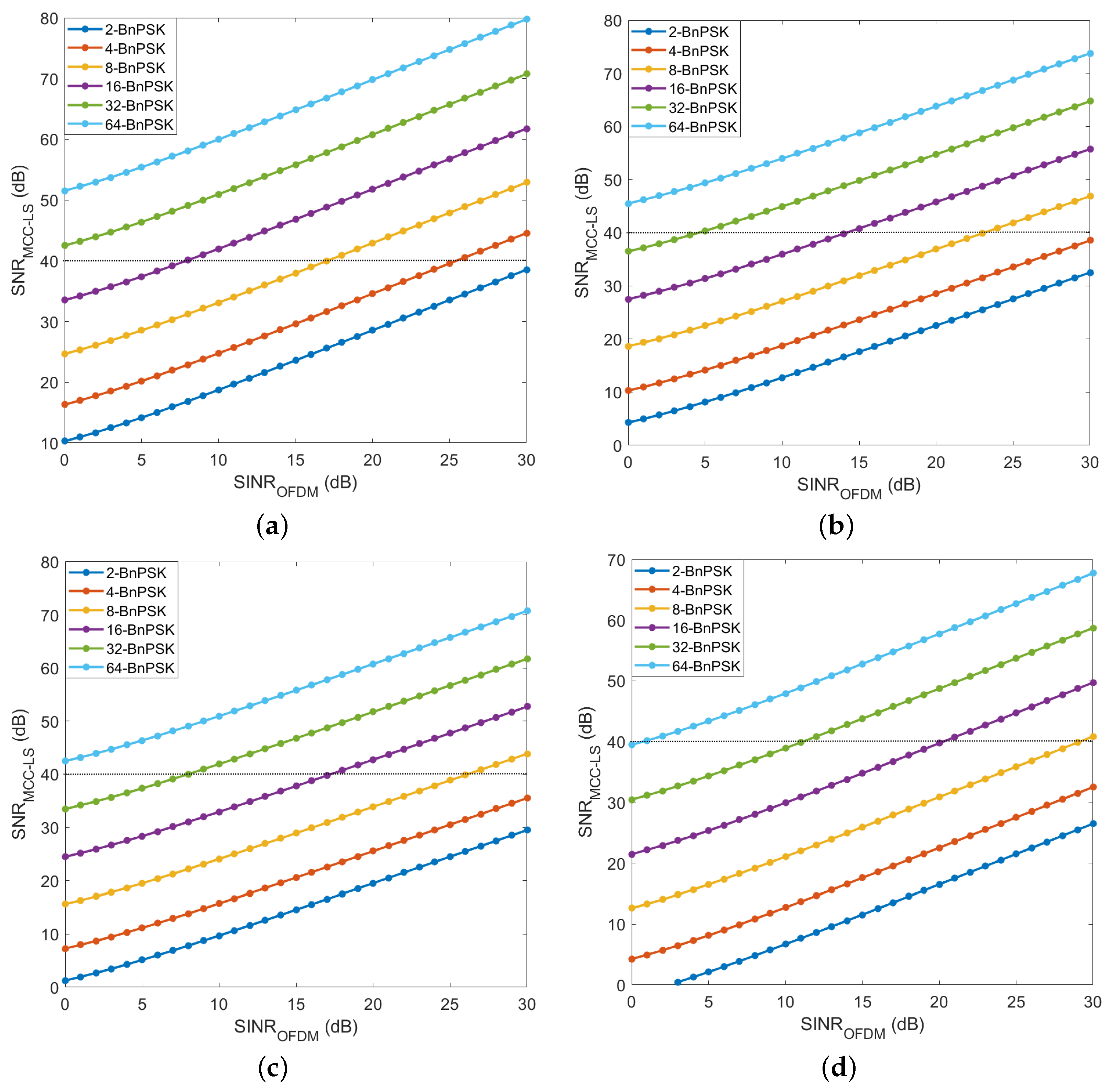
Figure 10, the relation between the required OFDM SINR and MCC SNR to target the FEC BER threshold for BPM modulation, at different BnPSK modulation orders, is illustrated. As shown in the figure, it is clear that the required
increases with the increase of
. As the
BnPSK modulation order is higher, more
is needed at the same
. However, the
requirement, with a range of interest below 40 dB, is decreased as
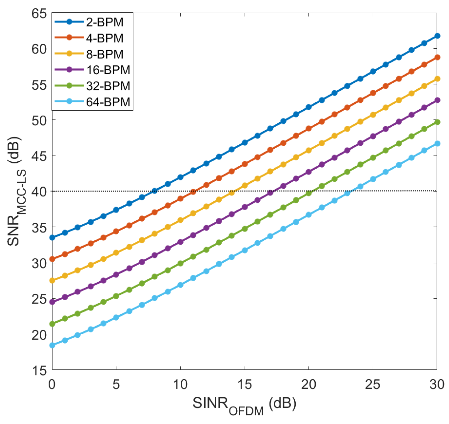
BPM modulation order is higher. This is highlighted in
Figure 11, which shows MCC SNR requirements against OFDM SINR for 8-BnPSK at varying BPM modulation orders to target the BER threshold for 8-BnPSK. In Equation (
25), BnPSK BER is derived based on Equation (
12) and MCC structure embedding
,
, and M-QAM OFDM:
Hence, it is concluded that increasing both -BPM and -BnPSK modulation orders results in better power efficiency at the cost of less spectral efficiency gain.
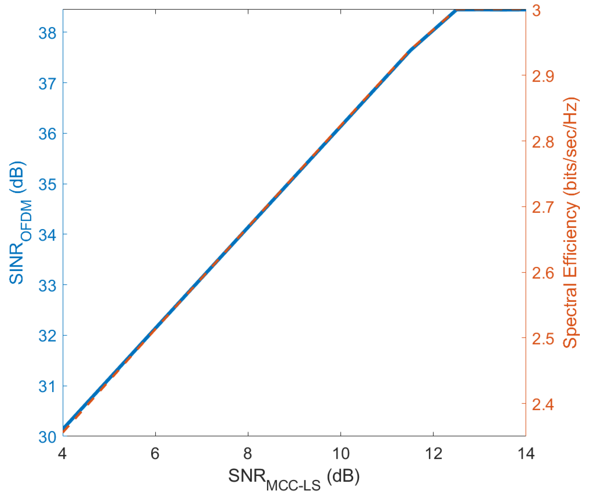
To maximize the spectral efficiency of MCC, the objective function in Equation (
24) is defined as a nonlinear optimization problem. The MATLAB optimization toolbox solver-based approach is utilized to obtain the optimum parameters for maximizing MCC spectral efficiency. Initial values for the problem variables fed into the model are obtained from the plots in
Figure 9,
Figure 10 and
Figure 11. Additionally, the BER threshold of
is set to be the minimum acceptable BER per MCC technology for solving this problem. A visualization of the optimum maximized MCC spectral efficiency power requirements is shown in
Figure 12. The relation between
and
is almost linear. As
increases from 4 dB to reach 14 dB, MCC maximized spectral efficiency range is 2.3–3 bits/s/Hz. The required
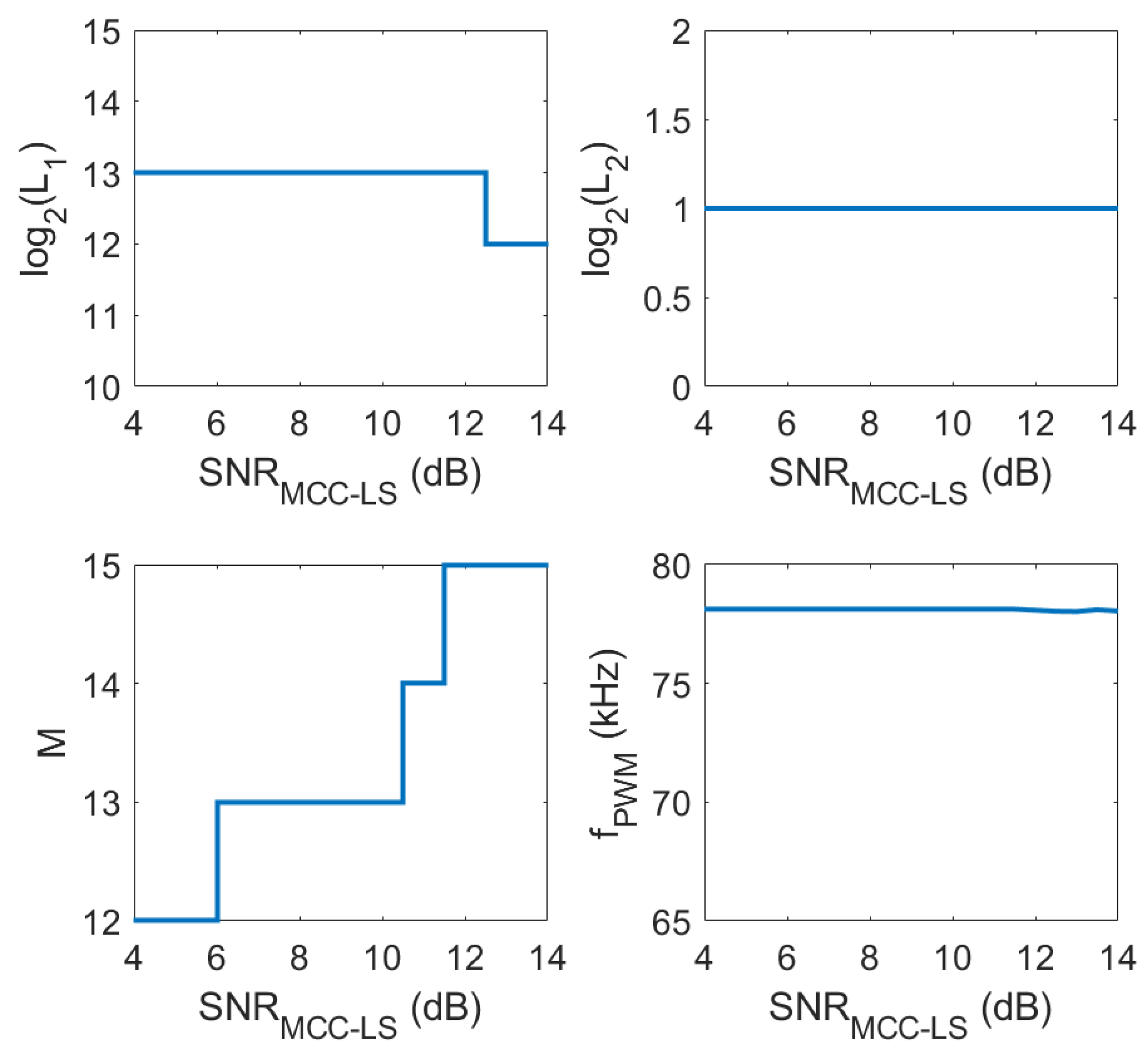
range is 30–38.5 dB. The optimum variables are shown in
Figure 13 for the same range of
, 4–14 dB. At this range, the maximum spectral efficiency is achieved by embedding 12–13 bits per BPM symbol, and 2-BnPSK within the MCC PWM-like envelope of frequency around 78.125 kHz, as shown in
Figure 13. Hence, the M-QAM modulation order controls the maximum obtained MCC spectral efficiency with a range of 12–15 bits per symbol.


