Abstract
Scaling rain attenuation parameters will significantly benefit the quick monitoring of rain attenuation in a particular channel with previously known results or in situ setup attenuation measurements. Most of the rain attenuation scaling techniques have been derived for slant links. In this study, we also applied frequency and polarization scaling techniques for terrestrial link applications. We collected real measured datasets from research paper publications and examined those datasets using International Telecommunication Union-Radiocommunication sector (ITU-R) models (P.530-17, P.618-13). Our analyzed results show that existing long-term frequency and polarization scaling rain attenuation models (ITU-R P.618-13 for slant links and ITU-R P.530-17 for terrestrial links) show reduced performance for frequency and polarization scaling measured locations in South Korea. Hence, we proposed a new scaling technique using artificial neural networks from the measured rain attenuation data of slant and terrestrial links in South Korea. The experimental results confirm that the proposed Artificial Neural Network (ANN)-based scaling model shows satisfactory performance to predict attenuation for frequency and vertical polarization scaling.
1. Introduction
Rain causes major attenuation of the propagated radio waves in terrestrial and satellite communication links. Since the fourth industrial revolution, the demand for high-volume data transmission has increased over the wireless network. Millimeter-wave (mm-wave) frequency is a promising solution that enables bandwidth to transfer high data volume. However, mm-wave frequency is highly disturbed by rain attenuation in terrestrial [1,2] and satellite telecommunication link [3] applications. Therefore, reliable rain attenuation prediction techniques must be incorporated into the system design process [4]. We know much about the rain attenuation information in existing frequency bands, but there is still research scope for mm-wave bands, even though significant research has already been conducted. In a particular area, if the rain attenuation information is well-known at a specific frequency, using that frequency and related information as a reference, the attenuation at other frequencies can be predicted; this procedure is called frequency scaling [5]. Thus, frequency scaling techniques can be helpful to estimate the attenuation at another frequency band for the quick management of terrestrial and slant links. In addition, real-time frequency attenuation scaling can be used in adaptive fade mitigation systems [6]. The idea of frequency scaling can be expanded to other rain attenuation parameters—polarization scaling, elevation angle scaling, and path length scaling—because rain attenuation is a function of these parameters. The significant problem of a scaling technique study is that it needs long-term experiments to be designed in a way that in the same experiment setup: (i) Use of different operating frequency bands are required to study frequency scaling, and (ii) Different polarization techniques and attenuation measurement are required for polarization scaling study. Long-term experimental results of a similar type are required for the elevation and path length scaling technique. Elevation angle scaling is a comparatively new concept, and the scaling mechanism is not much developed, or limited to LEO (Low Earth Orbit) satellites [7]. Frequency scaling can be implemented through a statistical or instantaneous application mechanism [8]. Statistical frequency scaling uses statistics from the primary measures (at a base frequency) to estimate the attenuation statistics at the target frequency. The average scaling of instantaneous frequency estimates whether statistical frequency scaling effects can be used for instantaneous frequency scaling [9]. Consequently, scaling-based rain attenuation prediction techniques can save time for quick operation of a radio link [10]. In [6], clear air and rainy condition-based instantaneous frequency scaling techniques were proposed. Usually, the rain attenuation value is given in dB and is determined by Sisl-Scars; it is noisy (where Sisl: instantaneous signal level, Scars: clear air reference signal), so a moving average filter is used to smooth the samples where the moving window duration is normally 30 s [6]. However, a larger window duration of 60 s is reported in [11]. A real-time frequency scaling technique was proposed in [10]. However, the downside of the proposed method is that the applicable frequency range is short in the range of 20–30 GHz. In [12] it was shown that the attenuation process may be considered as “jointly log-normal” distributed system (a log-normal model to describe the statistical behavior of rain-attenuation). Based on this assumption, the mean, standard deviation, and covariance parameters of the two frequencies were determined using the cumulative distribution function of the rain attenuation graph. The resulting covariance parameters indicate the correlation of the considered higher and lower frequency. In the literature, different types of power-law-based (PRB) rain attenuation scaling models have also been proposed [6]. According to the PRB frequency scaling technique, empirical relationships of a satellite link for two channels through approximating the ratio (where and correspond respectively for low and high frequency). In the literature, the value of n is proposed in the range of 1.72–2.0 [6,13]. In a gross sense, the rain attenuation scaling technique can be classified into long-term and short-term (instantaneous) applications. Some models can predict for short-term [10,14,15], and some of the models for long-term applications [16,17,18,19,20,21]. Most of the previous rain attenuation scaling methods fall in the slant link category. Compared to the slant links, the study of scaling of rain attenuation parameters is very limited for terrestrial links [22,23]. Although there are similarities between the terrestrial and slant links, many dissimilarities, for example, complex non-rainy atmospheric elements, such as clouds, gasses, and turbulence, exist in slant links [3,24]. Consequently, scaling models for slant links cannot be applied to terrestrial links without proper parameter considerations and validations. In [25,26,27], the performance of ITU-R models for the design of terrestrial and space communication systems was compared with the various well-known rain attenuation methods. Most models exhibit poor performance in a climatic area if the model has been developed in different climatic environments [28]. In [29], a polynomial-based frequency scaling technique was proposed from our communication and wave propagation lab. The current study is much different from the earlier study of frequency scaling regarding the approach followed for scaling. The earlier outcomes did not include the terrestrial links, but in this investigation, we propose an ANN-based frequency and polarization scaling technique applicable for both terrestrial and slant links. Recently, deep learning has become critical when evaluating the dynamic relationship between its input factors and the expected outcome [30]. The outcome of this study proposes an ANN-based frequency and polarization scaling technique which can also be considered as the long-term-based technique. The relationship in their specific ranges can be predicted by a supervised ANN with necessarily hidden nodes [31]. Fortunately, we have long-term experimental frequency and polarization measurement datasets for the terrestrial and slant links, facilitating this study. The significant contributions of this study are listed below.
- In this study, we collected experimentally measured dual-frequency attenuation datasets of terrestrial and slant links with time exceedance percentages of 0.1% and 0.01%, respectively. Subsequently, we applied compatible scaling techniques (frequency and polarization) that fit the collected datasets and examined prediction accuracy with existing scaling techniques.
- We developed an ANN to predict the attenuation for frequency and polarization scaling from the long-term-measured terrestrial and slant links attenuation datasets in South Korea.
The remainder of this paper is structured as follows. Section 2 presents the related literature analysis and the classification of various rain attenuation scaling techniques. Section 3 introduces the experimental configuration. Section 4 addresses the theoretical rain attenuation scaling model, whereas Section 5 compares the statistical effects. Finally, Section 6 presents the findings and recommendations of this study.
2. Rain Attenuation Scaling
Rainfall is a notable impediment to the transmission of mm-wave signals from the transmitter to the receiver. Raindrops can absorb, disperse, depolarize, and diffract the propagated wave [32]. In [33], 17 parameters have been listed that causes rain attenuation. All these parameters (or most significant of these parameters) are used to input a rain attenuation predictive model called the rain attenuation model, where attenuation is output. As per recent literature, scaling properties have been developed for four parameters: frequency, path length, polarization, and elevation angle. Consequently, considering the scaling-related parameters, rain attenuation (A) can be expressed as (1):
where L—path length in the rain, f—operating frequency, —elevation angle, and R—rainfall rate. However, scaling of the rain attenuation model for these parameters has not yet been developed. Among these parameters, four parameters: frequency, elevation angle, path length and polarization scaling techniques are proposed in the literature. In the next section, we will discuss the frequency, polarization, elevation angle and path length scaling technique as per the literature. Mathematically, scaling can be defined as:
where g: is the function that defines mappings of attenuation for frequency and polarization; —attenuation at frequency ; —attenuation at frequency ; —attenuation at horizontal polarization; —attenuation at vertical polarization. It is possible to determine the rain attenuation for another frequency using Equation (2). Likewise, using Equation (3), it is possible to determine the rain attenuation for vertical or horizontal polarization with the condition that the corresponding horizontal or vertical attenuation are known. In the next section, ITU-R implementations of the Equations (2) and (3) for terrestrial and slant links will be discussed.
The elevation scaling can be defined as the change in the attenuation complementary cumulative distribution function (CCDF) at distinct probability levels as a function of the elevation change. Following the procedure, as presented in (4), elevation scaling factor is determined as the ratio between the attenuation exceeded at elevation , and the one predicted with the simple “cosecant law” from the zenith path [7]:
where —attenuation exceeded with probability p at the elevation , —attenuation exceeded with probability p at the elevation ; in both cases the attenuation A is measured in .
The path length scaling normally comes along with the frequency scaling technique, as discussed in [34]. According to their presented results [34], a path length scaling technique along with frequency scaling can be combined. The cumulative distribution (CD) of rain attenuation from the selected reference path can be recalculated to the other two paths for the frequencies used, as in Equations (5)–(7):
where —attenuation on the base path, —attenuation on the target path, and —coefficients dependent on frequency for the base path, and —coefficients for the target path, —base link’s path length, —target link’s path length, and —path reduction factor.
2.1. Frequency Scaling
Rain attenuation models for frequency scaling are applicable if a different frequency signal passes through the same storm. It is helpful to measure the amount of rain attenuation that occurs at a given frequency. For example, it is helpful to have experimental results available at one frequency to estimate the rain attenuation at another frequency. Furthermore, frequency scaling techniques can help quickly predict rain attenuation at different frequencies. The application of frequency scaling can help determine the projected attenuation in a dual-frequency use of satellite communication, or predict attenuation at different frequencies [17,35]. Most of these scaling techniques were derived for slant links. As said earlier, scaling techniques can help to plan the link budget and fade mitigation technique applications over terrestrial links as well. In the literature, there have been efforts by researchers to find accurate frequency scaling techniques. These efforts are based on different techniques, such as empirical formula [36,37], consideration of the correlation between peak rain rate and corresponding attenuation [10], development of a line on a map that links points that have the same meteorological incidence called isopleths [12], the path-averaged raindrop size distribution [10], and rain inhomogeneity factor [38]. The ITU-R model can be used to predict frequency scaling as follows [36,37]:
where and are the rain attenuation at frequencies and (GHz), respectively; and H are defined by Equation (10) and Equation (11), respectively.
The applicable frequency of this model is limited to 7–55 GHz for slant path application [37] and 7–50 GHz for terrestrial path application [36].
2.2. Polarization Scaling
Polarization is the direction of the electric field in an electromagnetic wave. The commonly used polarization of radio waves is vertical, horizontal, right-hand circular, and left-hand circular. The ITU-R model P.530-17 [36] can predict the attenuation for vertical polarization, given that long-term attenuation statistics exist at a horizontal polarization and vice versa for a given terrestrial link. Mathematical formulas (Equations (12) and (13)) to determine the polarization conversion are given in [36]. The limitation of this model is that it does not apply in the case of circular polarization. According to [36], the rain attenuation of horizontal to vertical and vertical to horizontal polarization can be determined by:
where and are the attenuation due to vertical and horizontal polarization, respectively, and the frequency limit is up to 100 GHz. It is assumed to be valid in all parts of the world and path lengths up to 60 km.
2.3. Discussion on ITU-R Model: South Korea Perspective
The frequency and polarization scaling performance can be measured through available multi-band operating frequency attenuation datasets of different propagation measurement campaigns. To do so, we collected some experimentally measured attenuation datasets from around the world to assess the performance of the ITU-R model in predicting the frequency and polarization scaling. We found a limited number of such multi-band operating frequency campaigned rain attenuation measurement information for terrestrial and slant links. The collected datasets are given in Table 1 and Table 2, where Table 1 corresponds to terrestrial links and Table 2 corresponds to slant links. In both of these tables, the “(a)” section contains the collected datasets. To emphasize the maximum availability of the radio links, we tabulated the corresponding attenuation at 0.1% and 0.01% time exceedance, corresponding to the typical link availability of 99.9% and 99.99% over time. The “(b)” section of Table 1 and Table 2 contains some processed datasets: predicted attenuation, which is determined through the scaling prediction models and error in prediction, computed by Equation (14):
where is the predicted attenuation, and is the measured attenuation. A description of Table 1 and Table 2 is provided subsequently:

Table 1.
Prediction of attenuation through frequency scaling of experimental data for terrestrial links.
- In Table 1, some dual frequency-based experimental measured datasets are presented and the performance of frequency scaling of ITU-R P.530-17 is evaluated. The table shows the prediction error using the ITU-R [36] of terrestrial links with rain exceedance percentages of 0.1% and 0.01%. It is worth mentioning that, in radio network planning, the percentage of time exceedance helps determine link budget availability in horizontal and slant link designs. The availability indices used in link budget planning are typically 0.01 percent of the time exceedance used as link budget fade threshold. Above 0.01% of the time exceedance, the attenuation may lead to network outage. According to Table 1, the measured dataset in Italy showed comparatively good performance to predict attenuation at 83 GHz from the 73 GHz measured dataset. While the dataset in Korea from separate two experimental results ([42] and measured data by the National Radio Research Agency (RRA) [43] station—reported in Section 3) does not fit well by the ITU-R P.530-17 model, with showing errors 63% (at 83 GHz) [42], and 63% (at 38 GHz) for measured data by RRA [43].

Table 2.
Prediction of attenuation through frequency scaling of experimental data for slant links.
Table 2.
Prediction of attenuation through frequency scaling of experimental data for slant links.
| (a) | (b) | ||||||
|---|---|---|---|---|---|---|---|
| Ref. | F1 (GHz) | F2 (GHz) | A1 (dB) | A2 (dB) | ITU-R [37] | Error% [37] | |
| 0.1% | Japan [35] | 12.65 | 18.9 | 10 | 20 | 21 | −5 |
| Darmstadt [13] | 12.5 | 20 | 6 | 12 | 14 | 17 | |
| Darmstadt [13] | 20 | 30 | 12 | 24 | 23 | −4 | |
| Virginia Tech [44] | 12 | 20 | 5 | 15 | 13 | −13 | |
| Virginia Tech [44] | 20 | 30 | 12 | 25 | 23 | −8 | |
| Measured | 19.8 | 20.73 | 13 | 12 | 14 | 17 | |
| 0.01% | Japan [35] | 12.65 | 18.9 | 14 | 24 | 28 | 17 |
| Darmstadt [13] | 12.5 | 20 | 11 | 27 | 25 | −7 | |
| Darmstadt [13] | 20 | 30 | 27 | 51 | 47 | −8 | |
| Virginia Tech [44] | 12 | 20 | 12 | 29 | 29 | 0 | |
| Virginia Tech [44] | 20 | 30 | 29 | 44 | 50 | 14 | |
| Measured | 19.8 | 20.73 | 25 | 18 | 27 | 50 | |
- The relative errors due to frequency scaling of ITU-R P.618-13 model of slant links with rain times exceeding 0.1% and 0.01% are shown in Table 2. As we can see, the predicted error performance of the ITU-R model [37] shows good prediction ability for the data measured at Darmstadt [13] and data measured by Virginia Tech [44] at 20 GHz. On the other hand, the measured results in Korea showed a comparatively higher error generated by the ITU-R P.618-13 model.
3. Experimental Setup
In this section, we discuss the experimental scenario setup for the terrestrial and slant links, which is given as follows:
3.1. Terrestrial Links
Measurements of the received signal level (RSL) in dBm and precipitation rate (mm/h) campaigned at Icheon, Gyeonggi Province, South Korea during 2013–2015 by the RRA [43]. This measurement campaign was conducted over four links, but we report here three links with the same path length of 3.2 km, where frequency and polarization are as follows:
- 38 GHz vertical polarization
- 18 GHz horizontal polarization
- 18 GHz vertical polarization
The transmitter (Tx) of the measurement campaign was located at Khumdang tower station: Korea Telecom (KT) station ( N, E) and the receiver (Rx) was located at Icheon tower, RRA station ( N, E) as shown in Figure 1. The rain rate data are determined using an OTT Parsivel, a laser-based optical disdrometer, to measure the particle size and falling velocities of liquid and solid precipitation for every 10-s interval. The Rx end antenna is connected to two separate outdoor units, which are in turn connected to two indoor units via a 40 m coaxial cable. In addition, the data logger unit and the OTT Parsivel rain gauge are set up in the Rx end, where a rain gauge is installed at the top of the tower. The difference between RSL in a clear sky and RSL in rainy conditions for horizontal and vertical polarized signals at different rainfall rates are measured accordingly:
where is the attenuation measured in dB, is measured signal level in clear sky conditions, and is the measured signal level in rainy conditions. In this experiment, the attenuation due to gaseous changes in the atmosphere in the clear sky condition was not considered. Important parameters of the campaign are given in Table 3.
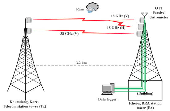
Figure 1.
Experimental setup for rain attenuation and rain rate measurement (terrestrial links); the figure is not drawn to scale.

Table 3.
Link parameters description [43,45].
3.2. Slant Links
Propagation measurements over an earth-space path were performed at Mokdong-13 na-gil ( N, E), Yangcheong-gu, Seoul, the Republic of Korea by the RRA [43]. In the experiment campaign, Ku and Ka-band signals were received through the earth station facility installed on the Korea Radio Promotion Association building rooftop, pointing toward Koreasat 6 satellite, at 12.25 and 20.73 GHz. Both of the receivers sample the data at a 10-s interval. Satellite links were 99.95% available, and the scheme for setup is shown in Figure 2. Furthermore, an optical disdrometer (OTT Parsivel) records the rainfall rates simultaneously with the satellite signal monitoring for all satellite links. As shown in Figure 2, the parabola offset antenna faces Koreasat 6. Detailed antenna specifications are given in Table 4. In addition, a separate low noise block converter was added for the circularly-polarized beacon signal at 12.25, 20.73 GHz of Koreasat 6. Attenuation due to rain is calculated by finding the difference between the RSL during clear sky conditions and RSL during rain as the Equation (15). Details of the experimental setup are discussed in [29].
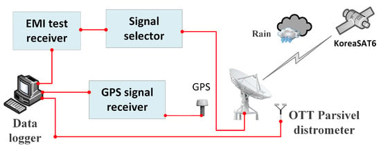
Figure 2.
Experimental setup for rain attenuation and rain rate measurement (slant links); the figure is not drawn to scale.

Table 4.
Specifications of the 12.25 and 20.73 GHz links for Koreasat 6 satellite link [43,46].
4. Proposed Model
Recently, learning and intelligence-based techniques have been proposed to enhance the rain attenuation model [33,45] and predict rainfall from rain attenuation of microwave links [24]. The ANN method is an intelligent system used for solving complicated problems in several applications such as prediction, optimization, modeling, simulation, pattern recognition, clustering, and others. ANN consists of three layers: the input layer, which collects data, one or more hidden layers used to connect the input and output layers, and an output layer that gives computed information. A neuron is the fundamental processing unit of ANN, which collects the inputs and production of the output. Each input is multiplied by connection weights, added to the biases, and then passed through an activation function to get an output.
We proposed a new prediction technique by applying a supervised artificial neural network (SANN) based on the measured attenuation data at two different frequencies of the same rain events. The neural network considered here is straightforward: including the single input, single hidden, and single output layer. The data were divided into 80% and 20% for training and testing of our proposed model, respectively. The dataset contains 162,720 input features and 162,720 targets of the received signal level for terrestrial and slant links.
An ANN is a function of the input weighted by a vector of weights plus a neuron bias , and is related to an activation function . For an N-layer network, the forward ANN propagation of an vector, which introduces several neurons and an activation function for each neuron, is mapped into the target output y for each layer, as shown in Figure 3 and Figure 4.
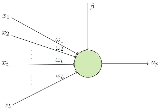
Figure 3.
Illustration of the used artificial neural network.
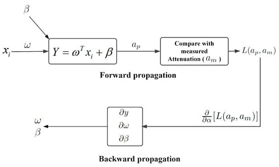
Figure 4.
Graphical representation of the forward and backward propagation in the neural network.
ANNs use the active feature in hidden layers to perform complex calculations and then move the result to the output layer. In this study, we consider the sigmoid function as follows:
where y and represent the transformation and activation functions of the layer, respectively, and w and represent the parameters of the transformation for the layer.
Backpropagation was used to reduce the error between the estimated and real measured attenuation. Backward distribution occurs from output to input through the neural network. Backpropagation measures the gradient proportional to the loss function in the weight space of a forward-distributed neural network. is used to calculate the disparity between the target output and computed output . For regression analysis problems, a squared error can be used as a loss function as follows [47]:
The next step is to compare the expected output with the target and determine the error and acceptable adjusting parameters, including weight and biases, to optimize efficiency. After forward propagation of the input to the output, it will be necessary to compare the expected output with the goal, evaluate the error, and adjust parameters, such as weight and biases, to yield optimal results. The cost function does not explicitly correlate network weights and bias; hence, a sensitivity measure must be identified to notify the changes and transmit them back to the input [48]. A stochastic gradient descent function is utilized in the following Equations (19) and (20) to change the biases and weights of the output layer:
where r represents the learning rate with respect to the output layer.
The loss function derivative measures the sensitivity of the changes in the loss function value as its input value is changed. The gradient denotes the input parameter that needs to be modified to minimize the loss function, as expressed below:
The and values are computed to update and , as shown in Equations (22) and (23), respectively. As a result, the weights and the biases are updated in Equations (19) and (20), respectively. The same neural network was used to calculate four types of scaling: 18 GHz to 38 GHz, 12 GHz to 20 GHz, 18 GHz (H) to 18 GHz (V), and 18 GHz (V) to 18 GHz (H), where the training datasets were according to Table 5.

Table 5.
Dataset descriptions of the predicted model.
5. Results and Discussion
This study considers the measured RSL data at low and high operating frequencies for frequency scaling and two type polarizations for polarization scaling. Rain attenuation, determined by the obtained RSL, was accomplished by determining the RSL difference between rainy and nonrainy times. Knowledge of the precipitation levels provides a rain attenuation prediction over the links.
What achieved the following:
- We applied the proposed ANN model to find frequency-scaled attenuation for the terrestrial link (see Figure 5);
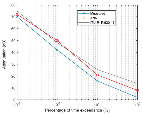 Figure 5. Predicted attenuation at 38 GHz using ANN and ITU-R frequency scaling techniques [36] from 18 GHz (terrestrial link).
 - We applied the proposed ANN model to find frequency-scaled attenuation for slant links (see Figure 6);
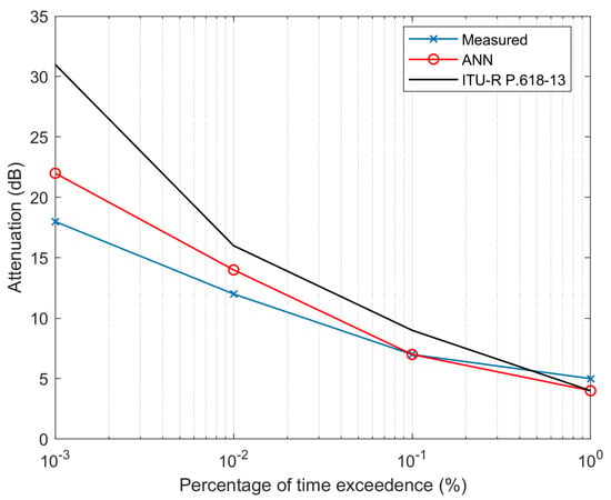 Figure 6. Predicted attenuation at 20 GHz using ANN and ITU-R frequency scaling techniques [37] from 12 GHz (slant link).
 - We applied the proposed ANN model to find the scaled attenuation for terrestrial link polarization scaling (see Figure 7);
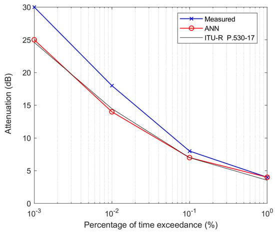 Figure 7. Predicted attenuation at 18 GHz vertical polarization from 18 GHz horizontal polarization using ANN and ITU-R polarization scaling techniques [36] from the measured terrestrial link.
 - We applied the proposed ANN model to find the scaled attenuation for polarization scaling (see Figure 8).
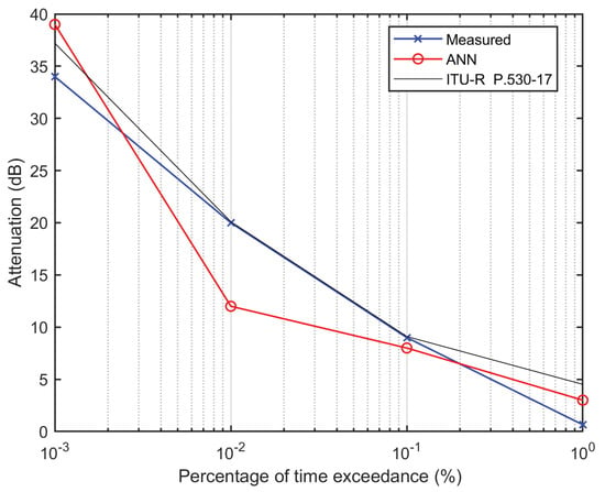 Figure 8. Predicted attenuation at 18 GHz horizontal polarization from 18 GHz vertical polarization using ANN and ITU-R polarization scaling techniques [36] from the measured terrestrial link.
As a result, the rain attenuation CCDF relation between the measured, scaled from the existing model, and the proposed models at different exceedance time percentages are plotted in Figure 5, Figure 6, Figure 7 and Figure 8. Figure 5 and Figure 6 present the frequency scaling for terrestrial and satellite links, respectively. Figure 7 and Figure 8 correspond to polarization scaling. A detailed description of these Figures is provided below:
- Figure 5 shows the measured attenuation versus the time exceedance percentage of the experimental terrestrial link using frequency scaling. Here, the measured attenuation means the attenuation obtained from the recorded RSL for the 38 GHz radio link. The red line marked by the small circle represents the predicted attenuation generated through the ANN network taking attenuation at 18 GHz as input and attenuation at 38 GHz as a target. In the same figure, the black line represents the attenuation obtained by scaling from 18 GHz to 38 GHz using the existing ITU-R P.530-17 formula. As shown in the figure, the overall attenuation predicted by the ANN model is well-matched to the measurement compared to the value predicted by the ITU-R P.530-17 scaled formula.
- Figure 6 shows the frequency scaling plot from 12 GHz to 20 GHz frequency for satellite links, and the description of this figure is almost the same as that in Figure 5, except for the slant link case application. The figure shows that the predicted attenuation through the ANN is closer to the measured result compared to the ITU-R scaled attenuation. Overall, the ANN model also showed good performance in predicting the attenuation of the slant link.
- Figure 7 depicts the performance of polarization scaling of rain attenuation comparison among measured, scaled through the ANN model, and scaled using the ITU-R model [36] at 18 GHz over the terrestrial link. The scaling was undertaken from the 18 GHz horizontal to the 18 GHz vertical polarization. Here, the ITU-R-generated attenuation was less compared to the measured attenuation. Considering the four points, at two points the proposed ANN model showed better performance than the ITU-R model, while for one point ANN and ITU-R are the same, and for one point, ANN did not show better performance than the ITU-R model. Therefore, the overall performance is satisfactory compared to the ITU-R P.530-17 scaled model.
- Figure 8 shows the reverse prediction technique compared to Figure 7, where the predicted attenuation is plotted for an 18 GHz horizontal link from the 18 GHz vertically polarized measured rain attenuation datasets. Here, the performance of the proposed ANN model is not satisfactory. On the other hand, the ITU-R model comparatively shows better prediction capability as the predicted attenuation matches the measured attenuation for most of the rain attenuation time exceedance.
6. Conclusions
The scaling of rain attenuation parameters with frequency and polarization is discussed in this study. In the literature review section, we compared the error performance (in Table 1 and Table 2) of the ITU-R model (P.530-17, P.618-13) with measured (collected) data. The results showed that ITU-R prediction models do not perform well for both terrestrial and slant paths considering rainfall rate-based attenuation in South Korea. The proposed artificial neural network-based predicted results showed satisfactory performance for frequency scaling concerning terrestrial and slant links. The predicated attenuation results from horizontal to vertical polarization are also satisfactory. However, the performance of horizontal attenuation results from vertical polarization does not outperform the ITU-R model. Thus, in summary, the proposed ANN-based model showed satisfactory performance for frequency scaling and predicting attenuation for vertical polarization scaling from horizontal polarization. It is expected that in wireless networks using 5G and beyond, substantial millimeter-wave links may be deployed where the operating frequency is within the frequency bands that are vulnerable to rain attenuation. In such a situation, the concept of frequency and horizontal to vertical scaling techniques can help quickly estimate rain attenuation. The paper outlines the basic steps to deploy an artificial intelligence platform to develop rain attenuation scaling prediction models, for both terrestrial and slant links. More data from diverse regions are necessary in order to provide efficient scaling models.
Author Contributions
M.A.S. anticipated, reviewed the related literature, evaluated, and outlined the rain fade models for earth-space links. D.-Y.C. played a significant role in coordinating research. M.A.S. conscripted the paper and subsequently modified and justified it by D.-Y.C. F.D.D. polishing and organizing the manuscript. All authors have read and agreed to the published version of the manuscript.
Funding
This study was supported by research fund from Chosun University, 2021.
Data Availability Statement
It could be provided upon request from the reader on the approval from National Radio Research Agency (RRA).
Acknowledgments
The writers would like to thank the editor and anonymous reviewers for their useful comments for improving the quality of this paper.
Conflicts of Interest
The authors declare no conflict of interest.
References
- Samad, M.A.; Diba, F.D.; Choi, D.Y. A Survey of Rain Attenuation Prediction Models for Terrestrial Links—Current Research Challenges and State-of-the-Art. Sensors 2021, 21, 1207. [Google Scholar] [CrossRef] [PubMed]
- Diba, F.D.; Afullo, T.J.; Alonge, A.A. Rainfall Rate and Attenuation Performance Analysis at Microwave and Millimeter Bands for the Design of Terrestrial Line-of-Sight Radio Links in Ethiopia. SAIEE Afr. Res. J. 2016, 107, 177–186. [Google Scholar] [CrossRef]
- Samad, M.A.; Diba, F.D.; Choi, D.Y. A Survey of Rain Fade Models for Earth–Space Telecommunication Links—Taxonomy, Methods, and Comparative Study. Remote Sens. 2021, 13, 1965. [Google Scholar] [CrossRef]
- Arapoglou, P.D.M.; Panagopoulos, A.D.; Cottis, P.G. An Analytical Prediction Model of Time Diversity Performance for Earth-Space Fade Mitigation. Int. J. Antennas Propag. 2008, 2008, 1–5. [Google Scholar] [CrossRef]
- Abdulrahman, A.Y.; Bin Abd Rahman, T.; Rahim, S.K.B.A.; Islam, M.R.U. A New Rain Attenuation Conversion Technique for Tropical Regions. Prog. Electromagn. Res. B 2010, 26, 53–67. [Google Scholar] [CrossRef][Green Version]
- Laster, J.D.; Stutzman, W.L. Frequency scaling of rain attenuation for satellite communication links. IEEE Trans. Antennas Propag. 1995, 43, 1207–1216. [Google Scholar] [CrossRef]
- Tomaz, L.M.; Capsoni, C.; Luini, L. Scaling Rain Attenuation as a Function of the Link Elevation. In Proceedings of the 2018 2nd URSI Atlantic Radio Science Meeting (AT-RASC), Gran Canaria, Spain, 28 May–1 June 2018; IEEE: Piscataway, NJ, USA, 2018. [Google Scholar] [CrossRef]
- Zemba, M.; Nessel, J.; Houts, J.; Luini, L.; Riva, C. Statistical analysis of instantaneous frequency scaling factor as derived from optical disdrometer measurements at K/Q bands. In Proceedings of the 2016 10th European Conference on Antennas and Propagation (EuCAP), Davos, Switzerland, 10–15 April 2016; IEEE: Piscataway, NJ, USA, 2016. [Google Scholar] [CrossRef]
- Cuervo, F.; Plimon, K.; Schonhuber, M.; Martellucci, A.; Castro, J.R. Alphasat Aldo Paraboni propagation experiment in Graz—Frequency scaling analysis. In Proceedings of the 2016 10th European Conference on Antennas and Propagation (EuCAP), Davos, Switzerland, 10–15 April 2016; IEEE: Piscataway, NJ, USA, 2016. [Google Scholar] [CrossRef]
- Acharya, R. A simple real-time frequency scaling technique for rain attenuation and its performance. Int. J. Satell. Commun. Netw. 2020, 38, 329–340. [Google Scholar] [CrossRef]
- Ulaganathen, K.; Rahman, T.A.; Rahim, S.K.A.; Islam, R.M. Review of Rain Attenuation Studies in Tropical and Equatorial Regions in Malaysia: An Overview. IEEE Antennas Propag. Mag. 2013, 55, 103–113. [Google Scholar] [CrossRef]
- Bertorelli, S.; Paraboni, A. Modelling of short-term frequency scaling for rain attenuation using ITALSAT data. Int. J. Satell. Commun. Netw. 2007, 25, 251–262. [Google Scholar] [CrossRef]
- Dintelmann, F.; Ortgies, G.; Ruecker, F.; Jakoby, R. Results from 12-to 30-GHz German propagation experiments carried out with radiometers and the Olympus satellite. Proc. IEEE 1993, 81, 876–884. [Google Scholar] [CrossRef]
- Karagiannis, G.A.; Panagopoulos, A.D.; Kanellopoulos, J.D. Short-Term Rain Attenuation Frequency Scaling for Satellite Up-Link Power Control Applications. IEEE Trans. Antennas Propag. 2013, 61, 2829–2837. [Google Scholar] [CrossRef]
- Kvicera, V.; Grabner, M.; Fiser, O. Frequency scaling of rain attenuation based on 4-year statistics obtained on two parallel terrestrial paths at 58 GHz and 93 GHz. In Proceedings of the 2012 42nd European Microwave Conference, Amsterdam, The Netherlands, 29 October–1 November 2012; IEEE: Piscataway, NJ, USA, 2012. [Google Scholar] [CrossRef]
- Kheirallah, H.; Olsen, R. Comparison of a one- and a two-frequency technique for frequency scaling of rain attenuation statistics. Electron. Lett. 1982, 18, 51. [Google Scholar] [CrossRef]
- Brisseau, O.; Mallet, C.; Barthes, L.; Marsault, T. Frequency scaling of rain attenuation based on microphysical characteristics for SatCom links. IEEE Proc. Microwaves Antennas Propag. 2006, 153, 523. [Google Scholar] [CrossRef]
- Kvicera, V.; Grabner, M.; Fiser, O. Frequency and polarization scaling of rain attenuation on 58 and 93 GHz terrestrial links. In Proceedings of the 2007 European Microwave Conference, Munich, Germany, 9–12 October 2007; IEEE: Piscataway, NJ, USA, 2007. [Google Scholar] [CrossRef]
- Usha, A.; Karunakar, G. Preliminary analysis of rain attenuation and frequency scaling method for satellite communication. Indian J. Phys. 2020, 95, 1033–1040. [Google Scholar] [CrossRef]
- Luini, L.; Panzeri, A.; Riva, C.G. Enhancement of the Synthetic Storm Technique for the Prediction of Rain Attenuation Time Series at EHF. IEEE Trans. Antennas Propag. 2020, 68, 5592–5601. [Google Scholar] [CrossRef]
- Laster, J.D. Frequency Scaling of Rain Attenuation on Satellite Links in the Ku/Ka-Bands Using OLYMPUS Satellite Data. Ph.D. Thesis, Virginia Tech, Blacksburg, VA, USA, 1993. [Google Scholar]
- Ihara, T.; Furuhama, Y. Frequency scaling of rain attenuation at centimeter and millimeter waves using a path-averaged drop size distribution. Radio Sci. 1981, 16, 1365–1372. [Google Scholar] [CrossRef]
- Islam, M.; Chebil, J.; Tharek, A. Frequency scaling of rain attenuation from 23- to 38-GHz microwave signals measured in Malaysia. In Proceedings of the 1999 Asia Pacific Microwave Conference. APMC’99. Microwaves Enter the 21st Century. Conference Proceedings (Cat. No.99TH8473), Singapore, 30 November–3 December 1999; IEEE: Piscataway, NJ, USA, 1999. [Google Scholar] [CrossRef]
- Diba, F.D.; Samad, M.A.; Ghimire, J.; Choi, D.Y. Wireless Telecommunication Links for Rainfall Monitoring: Deep Learning Approach and Experimental Results. IEEE Access 2021, 9, 66769–66780. [Google Scholar] [CrossRef]
- Mandeep, J.; Hassan, S.; Tanaka, K. Rainfall measurements at Ku-band satellite link in Penang, Malaysia. IET Microwaves Antennas Propag. 2008, 2, 147–151. [Google Scholar] [CrossRef]
- Yussuff, A.I.; Khamis, N.H. Rain Attenuation Modelling and Mitigation in The Tropics: Brief Review. Int. J. Electr. Comput. Eng. IJECE 2012, 2, 748–757. [Google Scholar] [CrossRef]
- Mandeep, J. Analysis of rain attenuation prediction models at Ku-band in Thailand. Adv. Space Res. 2012, 49, 566–571. [Google Scholar] [CrossRef]
- Allnutt, J. Evolutionary architectures for future multimedia services. In Proceedings of the IEE Colloquium: ‘What’s New in Satellite Communications?’, London, UK, 17 April 1996; IET: Stevenage, UK, 1996. [Google Scholar] [CrossRef]
- Shrestha, S.; Choi, D.Y. Characterization of Rain Specific Attenuation and Frequency Scaling Method for Satellite Communication in South Korea. Int. J. Antennas Propag. 2017, 2017, 1–16. [Google Scholar] [CrossRef]
- Theodoridis, S. Machine Learning: A Bayesian and Optimization Perspective; Academic Press: Cambridge, MA, USA, 2015. [Google Scholar]
- Thiennviboon, P.; Wisutimateekorn, S. Rain Attenuation Prediction Modeling for Earth-Space Links using Artificial Neural Networks. In Proceedings of the 2019 16th International Conference on Electrical Engineering/Electronics, Computer, Telecommunications and Information Technology (ECTI-CON), Pattaya, Thailand, 10–13 July 2019; IEEE: Piscataway, NJ, USA, 2019. [Google Scholar] [CrossRef]
- Shayea, I.; Rahman, T.A.; Azmi, M.H.; Islam, M.R. Real Measurement Study for Rain Rate and Rain Attenuation Conducted Over 26 GHz Microwave 5G Link System in Malaysia. IEEE Access 2018, 6, 19044–19064. [Google Scholar] [CrossRef]
- Samad, M.A.; Choi, D.Y. Learning-Assisted Rain Attenuation Prediction Models. Appl. Sci. 2020, 10, 6017. [Google Scholar] [CrossRef]
- Kvicera, V.; Grabner, M.; Fiser, O. Frequency and path length scaling based on long-term statistics of rain attenuation on terrestrial paths at 38 GHz and 58 GHz. In Proceedings of the 2012 6th European Conference on Antennas and Propagation (EUCAP), Prague, Czech Republic, 26–30 March 2012; IEEE: Piscataway, NJ, USA, 2012. [Google Scholar] [CrossRef]
- Chujo, W.; Manabe, T.; Yamamoto, S.i.; Suzuki, K. Dual frequency use technique for 40-GHz satellite communication during rainfall attenuation. In Proceedings of the 2015 International Symposium on Antennas and Propagation (ISAP), Hobart, Australia, 9–12 November 2015; IEEE: Piscataway, NJ, USA, 2015; pp. 1–3. [Google Scholar]
- ITU Radio Propagation Series. ITU-R P.530-17: Propagation Data and Prediction Methods Required for the Design of Terrestrial Line-of-Sight Systems; Report; ITU-R: Geneve, Switzerland, 2017. [Google Scholar]
- ITU-R Recommendations. P.618-13: Propagation Data and Prediction Methods Required for the Design of Earth-Space Telecommunication Systems; Report; ITU-R Recommendations: Geneve, Switzerland, 2017. [Google Scholar]
- Hodge, D. Frequency scaling of rain attenuation. IEEE Trans. Antennas Propag. 1977, 25, 446–447. [Google Scholar] [CrossRef]
- Filho, F.M.; Cole, R.; Sarma, A. Millimetre-wave rain induced attenuation: Theory and experiment. IEEE Proc. H-Microwaves Antennas Propag. 1986, 133, 308. [Google Scholar] [CrossRef]
- Budalal, A.A.H.; Islam, M.R.; Abdullah, K.; Rahman, T.A. Modification of Distance Factor in Rain Attenuation Prediction for Short-Range Millimeter-Wave Links. IEEE Antennas Wirel. Propag. Lett. 2020, 19, 1027–1031. [Google Scholar] [CrossRef]
- Luini, L.; Roveda, G.; Zaffaroni, M.; Costa, M.; Riva, C.G. The Impact of Rain on Short E -Band Radio Links for 5G Mobile Systems: Experimental Results and Prediction Models. IEEE Trans. Antennas Propag. 2020, 68, 3124–3134. [Google Scholar] [CrossRef]
- Kim, J.H.; Jung, M.W.; Yoon, Y.K.; Chong, Y.J. The measurements of rain attenuation for terrestrial link at millimeter wave. In Proceedings of the 2013 International Conference on ICT Convergence (ICTC), Jeju Island, Korea, 14–16 October 2013; IEEE: Piscataway, NJ, USA, 2013; pp. 848–849. [Google Scholar] [CrossRef]
- National Radio Research Agency (RRA). 767, Bitgaram-ro, Najusi, Jeollanam-do 58217, Korea. Available online: http://rra.go.kr/en/index.do (accessed on 19 August 2021).
- Stutzman, W.L.; Pratt, T.; Safaai-Jazi, A.; Remaklus, P.W.; Laster, J.; Nelson, B.; Ajaz, H. Results from the Virginia Tech propagation experiment using the Olympus satellite 12, 20 and 30 GHz beacons. IEEE Trans. Antennas Propag. 1995, 43, 54–62. [Google Scholar] [CrossRef]
- Diba, F.D.; Samad, M.A.; Choi, D.Y. The Effects of Rain on Terrestrial Links at K, Ka and E-Bands in South Korea: Based on Supervised Learning. IEEE Access 2021, 9, 9345–9355. [Google Scholar] [CrossRef]
- Shrestha, S.; Choi, D.Y. Rain Attenuation Study over an 18GHz Terrestrial Microwave Link in South Korea. Int. J. Antennas Propag. 2019, 2019, 1–16. [Google Scholar] [CrossRef]
- Musafer, H.; Abuzneid, A.; Faezipour, M.; Mahmood, A. An Enhanced Design of Sparse Autoencoder for Latent Features Extraction Based on Trigonometric Simplexes for Network Intrusion Detection Systems. Electronics 2020, 9, 259. [Google Scholar] [CrossRef]
- Abhishek, K.; Kumar, A.; Ranjan, R.; Kumar, S. A rainfall prediction model using artificial neural network. In Proceedings of the 2012 IEEE Control and System Graduate Research Colloquium, Shah Alam, Malaysia, 16–17 July 2012; IEEE: Piscataway, NJ, USA, 2012. [Google Scholar] [CrossRef]
Publisher’s Note: MDPI stays neutral with regard to jurisdictional claims in published maps and institutional affiliations. |
© 2021 by the authors. Licensee MDPI, Basel, Switzerland. This article is an open access article distributed under the terms and conditions of the Creative Commons Attribution (CC BY) license (https://creativecommons.org/licenses/by/4.0/).