Abstract
In this work, the authors introduce an entirely solar-powered LoRa-based WSN consisting of several nodes, two stoplights, and four cameras. The system has been used to monitor the semi-rural area of Panni (FG), Puglia, Italy. The WSN has a totally custom implementation in both the node-gateway side and the gateway-user interface side. In particular, the communication framework is entirely IoT-based, featuring both the MQTT protocol, for the direct control of apparatuses from the system user interface, and the more traditional TCP/IP protocol, implemented on NB-IoT. The proposed system is entirely solar-powered and features a 34.68 mWh/day consumption. Around a single communication session, the average power consumption inside the single node amounts to 1.4 mW. This paper gives an overview of the proposed system, with detailed explanations of each part, and measurements retrieved over a wide period to assess the functionality of the system.
1. Introduction
Rockfalls and landslides are hazardous geological events that pose significant threats to infrastructure, transportation networks, and human lives, particularly in mountainous and unstable terrains. Generally, these events are triggered by specific climatic and geological conditions, as well as human activity.
As a matter of fact, the disastrous consequences of a rockfall or landslide clearly demonstrate the need for monitoring systems in this matter. In particular, landslides cause around 4600 deaths yearly, with a frequency reaching 370 events per year [1]; consequently, statistical long-term monitoring, mostly motivated by the climate change scenario of the recent decade, hypothesizes a doubling of landslide occurrences in the next three decades [2]. Similarly, small-volume rockfall events are poorly documented, especially when land movements are not the main cause. In this regard, Coromias et al. analyzed the impact of fatal rockfalls based on non-seismic events in the Spanish nation, concluding that 60% of fatalities, on average, add up to 5 deaths per event [3]. These numbers confirm the need for monitoring networks and systems that prevent rockfall and landslide events. These apparatuses are mainly divided into two categories: mechanical-based systems and electronic-based systems. The first involves all the systems based on the physical containment of rocks and debris, such as rockfall and debris barriers [4,5,6], protection embankments [7,8], or rock drapery systems [9]. The electronic-based solutions consist of networks where the rockfall hazard is communicated to the user before it has occurrence, in some cases by using open spatial data infrastructures, as achieved by Fernandez et al. [10,11]. These systems were firstly based on wired standards [12]; then, multiple technologies were exploited for their implementation, such as terrestrial laser scanning (TLS) [13], infrared thermography (IRT) [14], optical very-high-resolution (VHR) data combined with analytical models [15], synthetic aperture radar (SAR) [16], or even the aid of external resources, such as satellites, through the global positioning system (GPS) [17] or unmanned aerial vehicles (UAV) [18]. Most recently, solutions based on optical fibers (OF) [19] and laser scanning [20] have been used to monitor and prevent land movements.
While these solutions allow the implementation of systems based on known protocols and standards, hence, with high reliability, and high specialization for the capture of specific aspects of the site under analysis, they frequently lack flexibility, total customizability and, especially in some cases, e.g., TLS, OF or UAVs, affordability in both costs and implementation; for this reason, along with real-time and continuous monitoring, wireless sensor networks (WSNs) have been used, even since before the first of the highly specialized solution reported above, as an alternative solution for rockfall and landslide monitoring. In particular, among the first documented WSNs in the literature, 2-axis strain gauges are used to assess the terrain status, in other words, the landslide risk [21]. This method was then developed by using different and more developed sensors, e.g., tilt sensors and micro electro-mechanical systems (MEMS) sensors, even providing a mix of them [22]. Energy efficiency in WSN is a critical aspect as it affects its autonomy. In particular, energy efficiency can be achieved both through hardware, by equipping renewable energy recharge mechanisms [23], and through software, by designing energy-efficient communication protocols [24]. In these terms, Giorgetti et al. implemented an energy-efficient protocol based on fault recovery, featuring event-driven functionalities.
Over the years, WSNs were developed by changing the standards according to the IoT-available protocols at the time, e.g., ZigBee [25,26]. More recently, the long-range (LoRa) technology [27] has become a notorious standard used in both industry and long-range wireless applications due to its communication technique, guaranteeing suitability for low-power applications, and the high communication distances that can be reached with it. Its use as an implementation standard for WSNs in rockfall monitoring has increased in recent years [28,29,30,31]. In particular, among the first studies about the LoRa feasibility in this context, Romdhane et al. propose the monitoring of an uninhabited hillside using the received signal strength indicator (RSSI) related to each node [28].
Furthermore, the feasibility of LoRa for rockfall and landslide monitoring was studied by the authors in past works, where several WSN installations were implemented through an established, standardized approach and documented through a custom user interface based on the NodeRed platform [32]. In this approach, the WSN relies on several general-purpose nodes equipped with commercial sensors and a LoRa antenna to communicate with a central gateway, acting as a protocol shifter. This configuration implements a star topology, characterized by ease of integration and management of nodes. Additionally, one of the targets of these systems is energy independence; hence, each part of them is equipped with a solar panel, enabling the system to provide for its power supply through solar energy in standard conditions.
The first implementation was located on the island of Pantelleria, Italy: the LoRaWAN protocol in the Media Access Control (MAC) layer was used in a zone under high risk of rockfall from a landslide [33]. This work saw the installation of inclinometers in the area of interest to monitor the inclination of several strategic points.
WSN with multiple types of sensors was achieved in [34]. Water level, humidity, and specific pole-shaped terrain inclination sensors were integrated into each WSN node, equipped with built-in inclinometers. Additionally, due to the vast area covered by this implementation, a custom low-level protocol that uses LoRa as a communication infrastructure, named LoRa peer-to-peer (LoRa P2P), was used for the first time. Specifically, all the nodes sent data from sensors, using LoRa P2P, to a signal repeater, employed to refresh and forward the signal towards the gateway, installed in a position covered by Long-Term Evolution (LTE). Furthermore, this system took into account the meteorological situation of the site through the use of a LoRa station working with LoRaWAN.
In this work, the authors introduce a novel WSN detection system for the management and containment of rockfalls in the locality of Panni, Puglia, Italy. The system comprises a multi-sensing structure, where inclination, environmental data, such as temperature and humidity, and visual data are extracted from the installation site. A stoplight is used to manage traffic in the area in case of a rockfall hazard. The primary aim of this work is to design a hybrid communication framework that ensures real-time wireless monitoring in hazardous mountainous zones with limited IoT coverage. In particular, LoRa technology is combined with Narrow Band IoT (NB-IoT) to maximize system reliability. In particular, this application employs both a custom LoRa-based protocol and a bidirectional double-approach communication framework between the system and the internet, hosting a custom user interface that operates with IoT protocols.
This paper is structured as follows: Section 2 describes the system, deepening its structure based on the communication languages used, the custom protocol, and how data is managed to implement the dual-approached bidirectional communication; Section 3 describes and depicts the structure of the single system parts, with an overview of their procedural operating principle; Section 4 shows on-field measurements, node-related measurements, and the proposed user interface; finally, Section 5, concludes this work.
2. System Overview
In this structure, the communication framework adopted in the presented system is described on multiple levels, in accordance with the reference communication standard.
2.1. High-Level Overview of the System
The front-end of the system is composed of inclinometric nodes, cameras, and a traffic light, which communicate bidirectionally with a LoRa-NB-IoT gateway. Each component of the system front-end communicates with a different protocol; in particular, the sensing nodes use low-level LoRa technology, while the traffic light and the camera use the higher-level IP protocol. Inclinometric nodes detect the hill inclination at several critical points. The cameras serve a visual purpose for the system, as they send images at regular intervals, and the traffic lights exert control on the road in the hazardous area. Data from the front end is sent to the LoRa-NB-IoT gateway and shifted from a low-level, specific protocol to higher-level ad hoc protocols for internet communication. Consequently, data is sent to a proprietary web server, where the decoding and forwarding to a human-friendly user interface is performed. The user interface is interactive. The described structure is reported below in Figure 1.
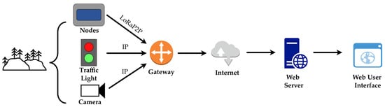
Figure 1.
Graphical high-level representation of the LoRa communication framework.
This high-level structure is based not only on general WSN structures, but it also ensures good modularity in the communication framework, as it is possible to easily find its source by scanning each single stage in case of any issues.
2.2. LoRa-P2P Protocol
As mentioned above, the subject area is monitored through inclinometer-based nodes, traffic lights, and video cameras. These nodes, installed in crucial locations, along with the other on-field components, send data by using the LoRa peer-to-peer (LoRa-P2P) protocol. Packets from this protocol have a custom format.
As shown in Figure 2, each node is identified on the packet by an 8-bit field; hence, this WSN is designed to contain up to 256 nodes. Since data has both an integer and a decimal part, the payload field of the custom LoRa-P2P packet has a 16-bit size and contains the node data converted to hexadecimal format to represent it with sufficient precision. Finally, the packet is counter-verified using the Cyclic Redundancy Check (CRC). Its content is based on the “x8 + x2 + x + 1” polynomial, with a size of 8 bits to ensure sufficient data integrity, since the system needs a significant number of nodes.
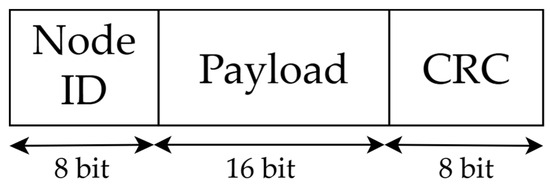
Figure 2.
LoRa-P2P protocol packet content.
2.3. Working Principle from the LoRa-NB-IoT Gateway to the User Interface
As mentioned above, the system features a custom architecture regarding the interfacing between system objects. In particular, as depicted in Figure 3, the LoRa-NB-IoT gateway data can be classified into two types, which differentiate into two different paths: data from nodes, and data from traffic lights and video cameras.
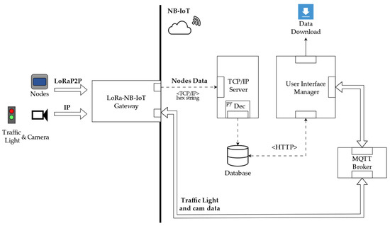
Figure 3.
Graphical representation of the above LoRa communication infrastructure.
In the former case, data from nodes involves acceleration, temperature, and humidity. Coherently with the LoRa-P2P packet, these data are encoded in a hexadecimal string and sent to a TCP/IP server through the corresponding communication protocol. Subsequently, the server decodes data through a Python 3.13 code block and sends it to a database using the HTTP protocol. As a result, the User Interface Manager (UIM) can access both current and past data from the database. Additionally, the UIM enables the local downloading of data on the device used; data can be downloaded in specific formats, such as csv, txt, pdf.
In the latter case, data from both traffic lights and video cameras is managed through higher-level protocols. In particular, both traffic light and camera nodes are equipped with an internal SIM and rely on the IP protocol, allowing them to access the network layer independently. As a matter of fact, the LoRa-NB-IoT gateway forwards the received IP packets to an MQTT broker, with bidirectional communication. The bidirectionality of communication with the UIM was implemented for test-related reasons. In this way, the user can directly control the status of the traffic lights from the UIM.
As a consequence, this structure enables both bidirectionality and protocol heterogeneity. These factors give both robustness to the system and flexibility, since they make it prone to eventual expansions and updates due to the use of IoT standards like MQTT.
3. Hardware Structure
In this section, particular attention is given to the hardware components used in each on-field-mounted system part.
3.1. Nodes Architecture
Nodes are the operative part of the system, as they retrieve inclinometric data from specific points on the installation site and send it to the local LoRa-NB-IoT gateway, which forwards packets to the internet. For this reason, nodes have an internal architecture based on both renewability and centralized control. As depicted in Figure 4, each node mounts an 80 × 45 mm solar panel on top of its package. The solar panel has a nominal voltage of 5 V, 90 mA as nominal current, hence, a 450 mW nominal power, and it is connected to an internal power path that charges a 2000 mAh Li-Po battery. The battery itself can reach up to 3.7 V, so its energy capacity is 7400 mWh. Additionally, by considering the solar panel voltage, the system reaches 74% recharging efficiency. The Li-Po battery is charged through the Texas Instruments BQ21040 battery charger (Dallas, TX, USA) and provides a 3.3 V constant voltage using the RP104 voltage regulator, from the Nisshinbo Micro Devices, Tokyo, Japan. This structure enables the system to operate entirely on renewable solar energy, reaching several weeks of power independence due to the low-power architectural and functional choices. In fact, by considering 2.3 h per day of Peak Sun Hours (PSH) in the installation location, and in the winter period [35], the daily collected energy equates to 765.9 mWh per day, as defined by Equation (1).
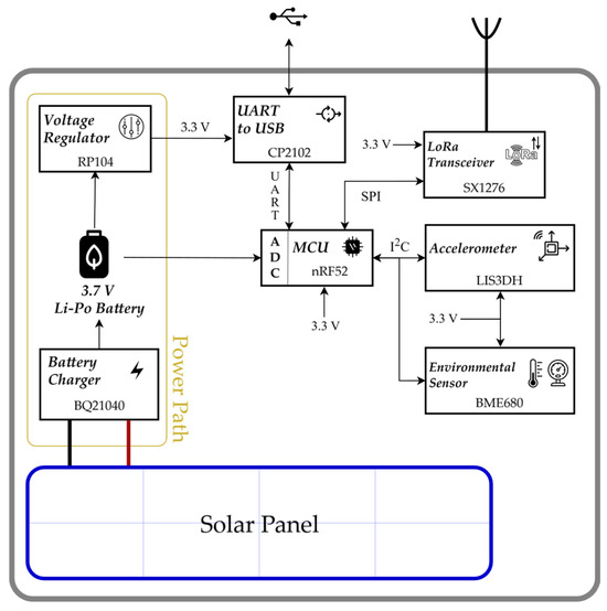
Figure 4.
Internal architecture of a single node.
The voltage from the Li-Po battery is read through an Analog-to-Digital Converter (ADC) by the Microcontroller Unit (MCU): the Nordic nRF52 (Trondheim, Norway) offers an ultra-low-power ARM Cortex-M4, a high-precision ADC, several robust timers, and a versatile SPI/UART interface to ensure efficient sensor acquisition and reliable control for the LoRa module. This choice enables a long-life, battery-powered architecture for rockfall-monitoring nodes with minimal maintenance.
As mentioned above, for optimal peripheral management, the architecture of the single node is centralized with respect to the MCU, since it oversees and controls both the node interfacing and its measurement operability. Among the interfacing blocks, the MCU controls universal serial bus (USB) interfacing through the Silicon Labs CP2102 driver (Austin, TX, USA) and LoRa communication through the Semtech SX1276 LoRa transceiver (Camarillo, CA, USA), properly connected to a LoRa antenna. The SX1276 enables reliable, low-power rockfall-monitoring communications over irregular areas, particularly due to its support for LoRa modulation with superior link budget, low receive current, and robust interference immunity. It also offers better sensitivity and coverage than many alternatives. Regarding nodal measurements, the MCU employs the I2C protocol to manage both the internal STMicroelectronics LIS3DH accelerometer (Plan-les-Ouates, Geneva, Switzerland) and the Bosch BME680 environmental sensor (Gerlingen, Baden-Württemberg, Germany). The former tracks node inclination, while the latter gathers temperature, humidity, and pressure information. In particular, the LIS3DH accelerometer detects the acceleration experienced by the node and converts it to an inclination accordingly with Equation (2).
The low power consumption, which is the primary aim of this work, justifies the choice of these components. In particular, Table 1 provides the current consumption of each node component according to its datasheet.

Table 1.
Summary of each node component with related current consumption.
As a result, the theoretical sleep-mode current consumption equates to around 130 μA.
The reported hardware is coordinated through a specific firmware structure reported in Figure 5. In particular, when the node is powered on, the internal sensors are initialized, and then the low-power sleep mode is reached. If an inclination event happens, which is the sudden variation of 3° on the node inclination, then the node wakes up. When the node awakens, sensors are read, and inclination is calculated through (2); then, the MCU reads the battery level through the internal ADC. After the reading stage, data is arranged into a LoRaP2P packet to be sent to the gateway. In particular, communication is attempted three times. In both cases of success or transmission attempts exceeding limits, the node returns to sleep mode. The number of attempts has been chosen to minimize the rate of lost messages during communication.
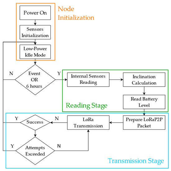
Figure 5.
Firmware-related sequence diagram for each node.
This WSN architecture was largely used in previous implementations and proved sufficient reliability due to its modularity, power independence, and multi-purpose working principle.
3.2. LoRa-NB-IoT Gateway Architecture
The LoRa-NB-IoT gateway is one of the most important elements in the system, as it gathers data from all the nodes using the LoRaP2P protocol and executes a data-level shift to send it to the internet, using the Narrow Band IoT (NB-IoT), to enable its readability on the user interface. The NB-IoT technology was chosen as it allows higher distances to be reached in critical situations, such as dense foliage.
As shown in Figure 6, the LoRa-NB-IoT gateway node is powered by a solar panel mounted on the same support pole. The current from the solar panel is managed by a BQ21040 battery charger to charge a Lithium Polymer Battery, whose charge level is read by the central MCU. Additionally, the voltage provided by the battery is regulated to 3.3 V through the RP104 voltage regulator, delivering a constant voltage supply for the other circuit components.
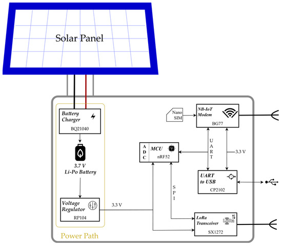
Figure 6.
Internal architecture of a single LoRa-NB-IoT gateway node.
Equally to the single nodes, the central MCU is a Nordic nRF52, chosen for the same performance reasons. The MCU is interfaced with the Semtech SX1272 LoRa transceiver for receiving data from nodes, a CP2102 UART-to-USB driver to enable LoRa-NB-IoT gateway re-programming, and a Quectel BG77 NB-IoT modem (Minhang District, Shanghai, China) equipped with a nanoSIM.
4. Measurements
This section presents the system user interface and reports measurements performed with this framework. In particular, this section introduces the application context, reports the current consumption measured on the single node and on-site inclination data retrieved from different nodes, and showcases the custom user interface.
4.1. Node Current Consumption
Since the system is classified as autonomous, with supply independence being one of its key features, this section reports the measurement of its power consumption during transmission and in idle mode. Specifically, measurements are executed using a Texas Instruments INA229 current monitor circuit. As per the datasheet [36], a 40 mΩ shunt resistor has been chosen for the measurement. As a result, Figure 7 reports the power consumption during a packet transmission procedure.
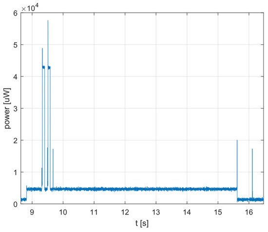
Figure 7.
Power consumption of a single node during packet sending.
As a result, in resting conditions, the power consumption amounts to 1.4 mW during the packet sending procedure, which lasts approximately 8 s; its average is 4.5 mW, while the peaks show around 43 mW of power. According to the node working routine, packets are sent either every 6 h or when a sudden variation in acceleration occurs. Hence, in the absence of any sudden variations and by calculating the average power over one day, the node has a power consumption of 34.68 mWh. From this result, the system harvests around 22 times the energy required for its activity. Additionally, the time needed to recover energy from one day of working is around 6 min and 15 s of peak sun.
According to the measurements aforementioned, the duty cycle in six hours is defined and calculated in (3).
In fact, the node spends 99.96% of its working time in sleep mode; hence, the energy required for transmission is negligible. Therefore, a variation in the communication period, e.g., doubling it to 12 h, would have a minimal impact on total daily consumption. This factor confirms the stability of the energetic design. Furthermore, the energy consumed for one attempt is approximately 0.01 mWh. Hence, even in the worst-case scenario where three attempts are required, the energy cost per session rises to 0.03 mWh. As a result, the impact of retransmissions is less than 0.11%. This channel occupancy drastically reduces the probability of packet collisions among the 40 nodes.
In terms of current, the average consumption in resting conditions is 424 μA, while the average node current during the packet-sending procedure is around 1.36 mA. The discrepancy between this measurement and the theoretical sleep-mode current consumption of around 130 μA is related to the presence of energy management and monitoring components. Among these, the contribution of the BQ21040 circuit is important, as well as the effect of quiescent and leakage currents. As a matter of fact, by considering the battery capacity Battcap and the daily power consumption dcons of the system, (4) explicates the theoretical autonomy, AutTh, of the system.
Consequently, the system is purposely oversized to maintain service during extended periods with low sunlight exposure.
4.2. Application Context
The rockfall containment system documented in this work was installed in the locality of Panni, Italy. Panni is a town situated in the Daunia mountain chain, which, according to the Italian national criteria for seismic classification, is classified as seismic zone “1” due to the high value of the registered horizontal acceleration, exceeding 0.25 g [37]. Specifically, this mountain zone lies in a tectonically active zone of the Italian southern Apennines, housing rocks containing soft clay, sandstones, or conglomerates [38]. In this sense, the presence of clay and sedimentary rocks creates weak slopes that are particularly sensitive to earthquake shaking, thus explaining the high level of risk in this zone.
Due to the high risk in the zone, the rockfall containment system introduced in this work is employed; both the location and its installation are reported in Figure 8.
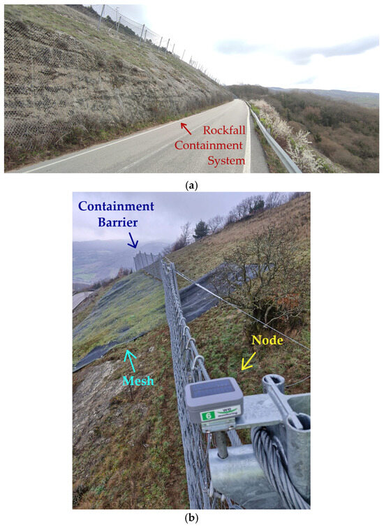
Figure 8.
Area under measurement (a) with rockfall containment equipment (b).
In particular, as shown in Figure 8a, the proposed rockfall containment system is installed on a rural slope above the road, facing a valley, while, as indicated by Figure 8b, the proposed system is composed of a containment mesh, whose anchor points host several inclination nodes to monitor the slope changes of the area in a grid-alike configuration; the entire system is delimited by a rockfall containment barrier, whose pillars host several nodes, in case of solid rocks incoming from the above area.
Additionally, due to the absence of physical obstacles and to the short–medium distance range between nodes and the LoRa-NB-IoT gateway, the spreading factor parameter for the node is set at SF9.
4.3. Node Measurements and Discussion
As mentioned above, the autonomous rockfall containment system relies on the use of 40 nodes to assess the implementation status at different points. As described in Section 3.1, each node has an internal multi-sensory system that enables the measurement of environmental parameters, such as the temperature, functional parameters, such as the battery charge, and technical parameters, such as the node inclination. This section reports measurements extracted from three critical nodes in the system: nodes 30, 33, and 35. Measurements are taken in a six-month time window.
The temperature, reported in Figure 9a–c, clearly shows the drift from winter to summertime, with several maximum and minimum points resulting from brief rainfall periods registered within the time window of interest. In particular, a minimum of around 0 °C is reached in the February period, while a maximum of 35 °C is reached in the August period.
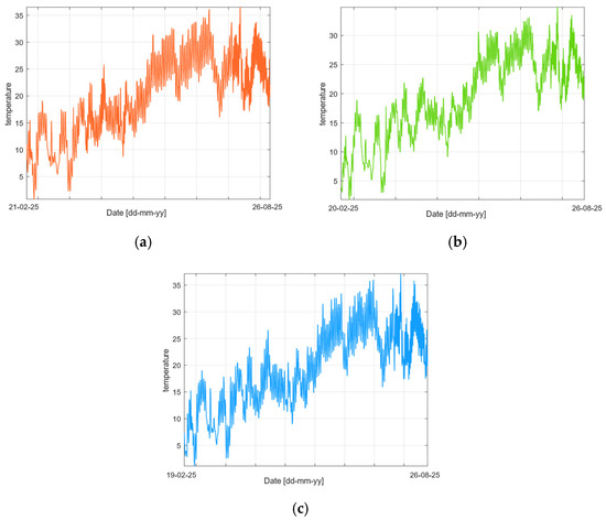
Figure 9.
Temperature measurements for nodes 30 (a), 33 (b), 35 (c).
Secondly, battery charge is taken into account to monitor the proper operation. In light of the current consumption measured and analyzed in Section 4.1, Figure 10 reports the battery charge of nodes 30 (Figure 10a), 33 (Figure 10b), and 35 (Figure 10c), in the considered six-month arc.
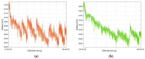
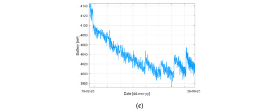
Figure 10.
Battery charge measurements for nodes 30 (a), 33 (b), 35 (c).
According to Section 3.1, the maximum battery charge amounts to 4140 mV. During the winter–spring period, the battery charge experiences a roughly linear decrease until it reaches 4000 mV. This value triggers the fine recharge mechanism, which brings the charge to approximately 4040 mV.
Among the three nodes, node 30 (Figure 10a) shows the highest number of recharge cycles. This characteristic is due to the node installation position; in fact, the node is installed on one of the rock mesh pillars. In the remaining cases, nodes 33 (Figure 10b) and 35 (Figure 10c) are installed on the mesh grid; hence, they are less exposed to sunlight, which explains their lower charge and lower recharge frequency.
To ease the hazard assessment, inclination data is represented as a variation from the initial value, stored when the nodes were mounted. In this regard, Figure 11a–c reports three critical nodes in the system, whose inclination differences were recorded in a six-month time window.
Figure 11.
X-axis inclination measurements for nodes 30 (a), 33 (b), 35 (c).
As a result, recorded inclinations are constant in almost all nodes, similar to the trend of node 35 (Figure 11c), where the inclination variation oscillates between −0.27° and −0.29°; nevertheless, some nodes experience a mild decreasing trend, linked to the morphology of the territory, as mentioned in the previous section. In fact, node 30 (Figure 11a) undergoes a decreasing inclination variation from −0.17° to −0.24°, while node 33 (Figure 11b) experiences a drift in the same value, from −0.3° to −0.35°.
An alarm is triggered when this difference value reaches 45°.
4.4. User Interface
The user interface was designed to ensure the maximum accessibility possible to the implementation data. As a matter of fact, Figure 12 reports the homepage of the user interface, which features the location of every active node in the area and shows the possibility of selecting a node to see its data.
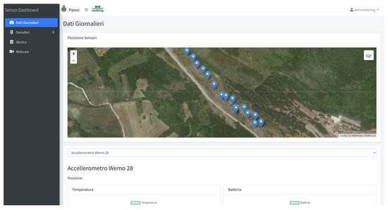
Figure 12.
Web user interface.
From the page, it is possible to access the historical data of nodes and export files in table or csv format to reconstruct the past trends. Additionally, it is possible to
- -
- Assess the status of traffic lights and manage them manually;
- -
- Assess the status of webcams and see their output.
In particular, for safety purposes, four 360-degree cameras are used; Figure 13 reports the location and output of one webcam, installed in the middle of the mesh grid.
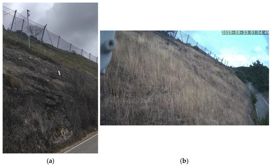
Figure 13.
Webcam location (a) and output (b).
The proposed user interface aims to maximize accessibility to system data and allows smooth status checking.
5. Discussion
The architecture proposed in this work has been designed to balance operational robustness and energetic sustainability in a critical mountainous environment. This section discusses the main criteria behind the primary choices for the presented system. In this regard, Table 2 reports a comparison between this work and the cited literature.
Table 2.
Comparison table.
Firstly, the choice of LoRa technology over other protocols, such as ZigBee or Bluetooth, was made due to the presence of non-licensed frequency bands, long-range, and low-power operation. While LoRa modulation is also employed in other frequency bands, such as the 915 MHz band [29], or 433/470 MHz [30], the selection of the 868 MHz band aligns with European LoRa implementations and is also the frequency utilized by legacy WSN systems like SLEWS [10,22]. In this work, the extended range was partially exploited since nodes are installed relatively close to the LoRa-NB-IoT gateway. Nevertheless, the choice of LoRa easily enables further system integrations, such as adding nodes in the valley nearby, without the need for repeaters. Furthermore, the adoption of star topology is a defining characteristic of LoRa and LoRaWAN networks. Star topology highly contrasts with other configurations, such as multi-hop architectures [10] or tree topologies [24]. The primary reason for this distinction lies in power consumption. In the chosen topology, nodes act as peers towards a common gateway, while in the other infrastructures, nodes act as both peers and packet routers. In this regard, minimizing the structural system complexity was the main criterion behind the choice of LoRa and star topology.
Secondly, the choice of LoRaP2P over LoRaWAN is motivated by the need to simplify the framework and minimize power consumption. As a matter of fact, LoRaWAN encompasses a comprehensive but more complex protocol stack [29], since it operates in the MAC layer. Hence, the use of LoRaWAN results in higher delays, higher costs, and lower customizability. On the other hand, LoRaP2P enables full customization of transmitted packets, allowing complete payload management directly on the physical layer. Yet, since LoRaP2P does not rely on a fixed framework, the proposed system, as-is, may lack security, whose role has become increasingly important nowadays. However, operating in the physical layer allows the integration of several high-layer standards independently from the lower-layer protocols, such as Sensor Observation Service (SOS) and XMPP/Jabber [10], or hybrid MAC/Network schemes, such as the CSMA/CA and TDMA combination. These standards, if integrated with the presented system, would improve energy efficiency and enable robust fault recovery capabilities [24]. As a matter of fact, LoRaP2P was chosen for its customizability and simple framework.
Lastly, the paradigms of renewability and wireless sensor networks led to the choice of solar panels and mobile connectivity. In fact, using solar energy as a supply is a robust and widely accepted strategy to ensure long-term autonomy in remote and hostile outdoor environments. The choice of node components was aimed at minimizing their power consumption in sleep mode, with reference to the low quiescent currents reported by Arnhardt et al. [22], Giorgetti et al. [24], and Romdhane et al. [28]. Nonetheless, the authors believe that implementing a deep-sleep routine for the nodes in the discussed system may maximize efficiency. Mobile connectivity was chosen over Ethernet to avoid wiring within the system. On the one hand, wiring was virtually possible, as the closest metropolitan area is approximately 10 km from the installed system; on the other hand, with this solution, more than one LoRaP2P signal repeater would have been necessary, as a hill obstructs communication between the system and the urban zone. Consequently, the use of repeaters not only increases system complexity but also increases power consumption and the risk of message loss. For this reason, since the installation area has NB-IoT coverage, the entirely wireless solution using mobile connectivity was chosen, at a slightly higher cost.
6. Conclusions
In this work, a rockfall monitoring system with a specific internal structure was presented. The system consists of a wireless sensor network specifically designed for the use of LoRa technology. In particular, a custom LoRa protocol is used on the front side of the system; its communication with the internet is managed through server–database communication, accessed from the custom user interface. As a result, the achieved power consumption in sleep mode is competitive with similar systems in the literature, while providing a reliable, user-friendly way to monitor an area with high rockfall risk at the lowest expenses due to the use of a WSN. The main system novelty lies in its custom and entirely wireless nature. In particular, the combined use of LoRa and NB-IoT, with specific energy-oriented design considerations, provides reliability and novelty to the system.
In future implementations, the authors aim to make structural updates to this system, such as a structure based on peer-to-peer or asynchronous token-based communication, rather than the usual star topology structure, as well as the integration of novel sensors and artificial intelligence for hazard modeling.
Author Contributions
Conceptualization, P.E.; methodology, V.S.; software, P.E.; validation, G.F., V.S. and P.E.; formal analysis, G.F.; investigation, P.E.; resources, V.S.; data curation, P.E.; writing—original draft preparation, P.E. and V.S.; writing—review and editing, G.F. and V.S.; visualization, G.F. and V.S.; supervision, G.F. and V.S.; project administration, V.S.; funding acquisition, V.S. All authors have read and agreed to the published version of the manuscript.
Funding
This research received no external funding.
Data Availability Statement
The original contributions presented in this study are included in the article. Further inquiries can be directed to the corresponding authors.
Acknowledgments
The authors acknowledge WeMonitoring srl, Daniele Rossi, and Gheller SpA for the implementation and mounting of the system.
Conflicts of Interest
The authors declare no conflicts of interest.
References
- Farvacque, M.; Corona, C.; Lopez-Saez, J.; Mainieri, R.; Stoffel, M.; Bourrier, F.; Eckert, N.; Toe, D. Estimating Rockfall Release Frequency from Blocks Deposited in Protection Barriers, Growth Disturbances in Trees, and Trajectory Simulations. Landslides 2022, 19, 7–18. [Google Scholar] [CrossRef]
- Wang, X.; Wang, Y.; Lin, Q.; Yang, X. Assessing Global Landslide Casualty Risk Under Moderate Climate Change Based on Multiple GCM Projections. Int. J. Disaster Risk Sci. 2023, 14, 751–767. [Google Scholar] [CrossRef]
- Corominas, J.; Lantada, N.; Núñez-Andrés, M.A.; Mavrouli, O.C. Fatal Non-Seismic Rockfalls in Spain. Geoenviron. Disasters 2025, 12, 17. [Google Scholar] [CrossRef]
- Peila, D.; Pelizza, S.; Sassudelli, F. Evaluation of Behaviour of Rockfall Restraining Nets by Full Scale Tests. Rock Mech. Rock Eng. 1998, 31, 1–24. [Google Scholar] [CrossRef]
- Vagnon, F.; Segalini, A.; Ferrero, A.M. Studies of Flexible Barriers Under Debris Flow Impact: An Application to an Alpine Basin. Procedia Earth Planet. Sci. 2015, 15, 165–172. [Google Scholar] [CrossRef]
- Volkwein, A.; Gerber, W.; Klette, J.; Spescha, G. Review of Approval of Flexible Rockfall Protection Systems According to ETAG 027. Geosciences 2019, 9, 49. [Google Scholar] [CrossRef]
- Volkwein, A.; Schellenberg, K.; Labiouse, V.; Agliardi, F.; Berger, F.; Bourrier, F.; Dorren, L.K.A.; Gerber, W.; Jaboyedoff, M. Rockfall Characterisation and Structural Protection—A Review. Nat. Hazards Earth Syst. Sci. 2011, 11, 2617–2651. [Google Scholar] [CrossRef]
- Lambert, S.; Bourrier, F. Design of Rockfall Protection Embankments: A Review. Eng. Geol. 2013, 154, 77–88. [Google Scholar] [CrossRef]
- Bertolo, P.; Oggeri, C.; Peila, D. Full-Scale Testing of Draped Nets for Rock Fall Protection. Can. Geotech. J. 2009, 46, 306–317. [Google Scholar] [CrossRef]
- Fernandez-Steeger, T.; Arnhardt, C.; Walter, K.; Haß, S.; Niemeyer, F.; Nakaten, B.; Homfeld, S.; Asch, K.; Azzam, R.; Bill, R.; et al. SLEWS—A Prototype System for Flexible Real Time Monitoring of Landslides Using an Open Spatial Data Infrastructure and Wireless Sensor Networks. Geotechnol. Sci. Rep. 2009, 13, 3–15. [Google Scholar]
- Thakur, M.; Dhiman, R.K.; Singh, S.; Aggarwal, N.; Bourrier, F. Development of Rockfall Early Warning System (REWS) for Prediction of Rockfall Hazard in Manikaran, NW Himalaya, India. J. Geol. Soc. India 2025, 101, 437–445. [Google Scholar] [CrossRef]
- Ghazanfari, E.; Yoon, S.-U.; Dong, Y.; Li, X.; Medina, C.I.; Seserko, D.; Cheng, L.; Yun, T.S.; Pamukcu, S. Subsurface Geo-Event Monitoring Using Wireless Sensor Networks. In Geo-Frontiers 2011: Advances in Geotechnical Engineering; American Society of Civil Engineers (ASCE): Reston, VA, USA, 2011; pp. 1732–1742. [Google Scholar]
- Ardizzone, F.; Basile, G.; Cardinali, M.; Casagli, N.; Del Conte, S.; Del Ventisette, C.; Fiorucci, F.; Garfagnoli, F.; Gigli, G.; Guzzetti, F.; et al. Landslide Inventory Map for the Briga and the Giampilieri Catchments, NE Sicily, Italy. J. Maps 2012, 8, 176–180. [Google Scholar] [CrossRef]
- Spampinato, L.; Calvari, S.; Oppenheimer, C.; Boschi, E. Volcano Surveillance Using Infrared Cameras. Earth. Sci. Rev. 2011, 106, 63–91. [Google Scholar] [CrossRef]
- James, M.R.; Robson, S. Straightforward Reconstruction of 3D Surfaces and Topography with a Camera: Accuracy and Geoscience Application. J. Geophys. Res. Earth Surf. 2012, 117. [Google Scholar] [CrossRef]
- Barla, M.; Antolini, F. An Integrated Methodology for Landslides’ Early Warning Systems. Landslides 2016, 13, 215–228. [Google Scholar] [CrossRef]
- Fanos, A.M.; Pradhan, B.; Mansor, S.; Yusoff, Z.M.; Abdullah, A.F.B. A Hybrid Model Using Machine Learning Methods and GIS for Potential Rockfall Source Identification from Airborne Laser Scanning Data. Landslides 2018, 15, 1833–1850. [Google Scholar] [CrossRef]
- Erdelj, M.; Król, M.; Natalizio, E. Wireless Sensor Networks and Multi-UAV Systems for Natural Disaster Management. Comput. Netw. 2017, 124, 72–86. [Google Scholar] [CrossRef]
- Ravet, F.; Briffod, F.; Goy, A.; Rochat, E. Mitigation of Geohazard Risk along Transportation Infrastructures with Optical Fiber Distributed Sensing. J. Civ. Struct. Health Monit. 2021, 11, 967–988. [Google Scholar] [CrossRef]
- Weidner, L.; Walton, G. Monitoring the Effects of Slope Hazard Mitigation and Weather on Rockfall along a Colorado Highway Using Terrestrial Laser Scanning. Remote Sens. 2021, 13, 4584. [Google Scholar] [CrossRef]
- Sheth, A.; Tejaswi, K.; Mehta, P.; Parekh, C.; Bansal, R.; Merchant, S.; Singh, T.; Desai, U.B.; Thekkath, C.A.; Toyama, K. SenSlide: A Sensor Network Based Landslide Prediction System. In Proceedings of the 3rd International Conference on Embedded Networked Sensor Systems; Association for Computing Machinery: New York, NY, USA, 2005; pp. 280–281. [Google Scholar]
- Arnhardt, C.; Fernandez-Steeger, T.M.; Azzam, R. Sensor Fusion in an Ad Hoc Multi-Hop Sensor Network for Real-Time Monitoring of Landslides Endangering Human Infrastructures. Geotechnol. Sci. Rep. 2009, 15, 38–49. [Google Scholar]
- Singh, J.; Kaur, R.; Singh, D. Energy Harvesting in Wireless Sensor Networks: A Taxonomic Survey. Int. J. Energy Res. 2021, 45, 118–140. [Google Scholar] [CrossRef]
- Giorgetti, A.; Lucchi, M.; Tavelli, E.; Barla, M.; Gigli, G.; Casagli, N.; Chiani, M.; Dardari, D. A Robust Wireless Sensor Network for Landslide Risk Analysis: System Design, Deployment, and Field Testing. IEEE Sens. J. 2016, 16, 6374–6386. [Google Scholar] [CrossRef]
- Wang, H.; Tuo, X.; Xi, D.; Fan, L.; Zhang, Z.; Zhang, G.; Hao, S. Research on One ZICM2410-Based Wireless Sensor Network for Landslide Monitoring. In Proceedings of the 2011 7th International Conference on Wireless Communications, Networking and Mobile Computing, Wuhan, China, 10–12 October 2011; pp. 1–4. [Google Scholar]
- Janeras, M.; Jara, J.-A.; Royán, M.J.; Vilaplana, J.-M.; Aguasca, A.; Fàbregas, X.; Gili, J.A.; Buxó, P. Multi-Technique Approach to Rockfall Monitoring in the Montserrat Massif (Catalonia, NE Spain). Eng. Geol. 2017, 219, 4–20. [Google Scholar] [CrossRef]
- Semtech Corp. LoRa and LoRaWAN. Available online: https://www.semtech.com/uploads/technology/LoRa/lora-and-lorawan.pdf (accessed on 25 January 2026).
- Fekih Romdhane, R.; Lami, Y.; Genon-Catalot, D.; Fourty, N.; Lagrèze, A.; Jongmans, D.; Baillet, L. Wireless Sensors Network for Landslides Prevention. In Proceedings of the 2017 IEEE International Conference on Computational Intelligence and Virtual Environments for Measurement Systems and Applications (CIVEMSA), Annecy, France, 26–28 June 2017; pp. 222–227. [Google Scholar]
- Muladi, M.; Wirawan, I.M.; Lestari, D.; Choirul, S.; Raka, E.; Leksono, A.; Qodri, F.; Prasetyo, S. Chirpstack-Based LoRAWAN Platform for Land-Sliding Monitoring System. Instrum. Mes. Métrologie 2025, 24, 73–79. [Google Scholar] [CrossRef]
- Tseng, K.-H.; Chung, M.-Y.; Chen, L.-H.; Huang, Y.-W. Implementation of Composite LPWAN on the Slope Disaster Prevention Monitoring System. IEEE Sens. J. 2022, 22, 2658–2671. [Google Scholar] [CrossRef]
- Wang, C.; Guo, W.; Yang, K.; Wang, X.; Meng, Q. Real-Time Monitoring System of Landslide Based on LoRa Architecture. Front. Earth Sci. 2022, 10, 899509. [Google Scholar] [CrossRef]
- Node-RED, v4.1.5; OpenJS Foundation: San Francisco, CA, USA, 2025. Available online: https://nodered.org/ (accessed on 1 February 2026).
- Ragnoli, M.; Leoni, A.; Barile, G.; Ferri, G.; Stornelli, V. LoRa-Based Wireless Sensors Network for Rockfall and Landslide Monitoring: A Case Study in Pantelleria Island with Portable LoRaWAN Access. J. Low Power Electron. Appl. 2022, 12, 47. [Google Scholar] [CrossRef]
- Esposito, P.; Ragnoli, M.; Barile, G.; Leoni, A.; Ferri, G.; Stornelli, V. A Multi-Level LoRa Application for Underwood Monitoring. In Proceedings of the 2023 16th International Conference on Advanced Technologies, Systems and Services in Telecommunications (TELSIKS), Nis, Serbia, 25–27 October 2023; pp. 251–254. [Google Scholar]
- Beale, A. Peak Sun Hours Calculator. Available online: https://footprinthero.com/peak-sun-hours-calculator (accessed on 29 January 2026).
- Texas Instruments Inc. INA229 85-V, 20-Bit, Ultra-Precise Power/Energy/Charge Monitor with SPI Interface; Texas Instruments Inc.: Dallas, TX, USA, 2022. [Google Scholar]
- Governo Italiano—Dipartimento della Protezione Civile. O.P.C.M. 3274 del 20 Marzo 2003 Primi Elementi in Materia di Criteri Generali per la Classificazione Sismica del Territorio Nazionale e di Normative Tecniche per le Costruzioni in Zona Sismica; Dipartimento della Protezione Civile: Rome, Italy, 2003.
- Pisano, L.; Ardizzone, F.; Bucci, F.; Cardinali, M.; Fiorucci, F.; Santangelo, M.; Zumpano, V. Lithological and Morpho-Structural Control on Landslide Distribution in the Daunia Apennines, Southern Italy. In Proceedings of the EGU General Assembly Conference, Vienna, Austria, 23–28 April 2023; p. EGU-2076. [Google Scholar]


Disclaimer/Publisher’s Note: The statements, opinions and data contained in all publications are solely those of the individual author(s) and contributor(s) and not of MDPI and/or the editor(s). MDPI and/or the editor(s) disclaim responsibility for any injury to people or property resulting from any ideas, methods, instructions or products referred to in the content. |
© 2026 by the authors. Licensee MDPI, Basel, Switzerland. This article is an open access article distributed under the terms and conditions of the Creative Commons Attribution (CC BY) license.