Article

Fabrication of Ultra-High-Performance PVDF-HFP Air Filters by Electrospinning

1
Department of Mechanical, Automotive, and Materials Engineering, University of Windsor, Windsor, ON N9B 3P4, Canada
2
River Drive Manufacturing, Oakville, ON L6M 2Y1, Canada
3
NanoPhyll Inc., Montreal, QC H4S 2A4, Canada
*
Author to whom correspondence should be addressed.
Fibers 2023, 11(8), 71; https://doi.org/10.3390/fib11080071
Submission received: 5 July 2023 / Revised: 13 August 2023 / Accepted: 16 August 2023 / Published: 21 August 2023

Abstract

:
This research aims to fabricate hydrophobic electrospun air filters with ultra-high performance against virions. In order to achieve this goal, constant basis weight electrospun poly(vinylidene fluoride-co-hexafluoropropylene) (PVDF-HFP) with low-bead, high-bead, and ultra-high-bead fibre structures were used to fabricate single and multilayer filters by controlling the Dimethylformamide (DMF)-to-acetone ratio of the solvent. The water contact angle of the fabricated layers ranged from 131° for low-bead structures to 135° for ultra-high-bead structures, indicating their overall high hydrophobicity. The size-resolved filtering efficiency and pressure drop tests on the fabricated filters showed that low-bead structure for both single and multilayer filters and high-bead structure for single-layer filters enhance the quality factor remarkably. The results showed that the single-layer ultra-high-bead structure air filters had a filtering efficiency of 99.33%, superior to N95 air filters (96.54%) and comparable to double N95 filters (99.86%). However, the electrospun air filter showed a pressure drop of 169.3 Pa and a quality factor of 27.6 × 10 3   P a 1 compared to a pressure drop of 388 Pa and quality factor of 16.9 × 10 3   P a 1 for double N95 air filters. Therefore, it has a high potential to be used as the filtration media in hospitals, long-term care centers, and masks to provide superior protection against virions for healthcare providers and patients.

1. Introduction

The COVID-19 pandemic revealed the weakness of protective equipment against airborne viral infections [1]. The size of airborne viruses can be as small as 50–200 nm [2], making them a challenge to block entirely with conventional face masks on the market. The infectious dose for virions is estimated to be around several hundred particles [3]. Because of the estimated low infectious dose, the efficiency of the face mask should be as high as possible to protect users, especially healthcare workers, who may be exposed to the virus for an extended period of time [4,5].
The melt-blown technique is usually used to make the mask air filters with fibre diameters of 1–5 µm. The high production rate and ability to process most of the polymers are the main advantages of this method [6]. However, this technique cannot produce ultrafine (submicron and nano) fibres [7], and the fibres have almost a neutral charge. Therefore, post-processes such as corona discharge, triboelectrification, or liquid contact are required to charge the filters [8] to improve the filtering efficiency for the ultrafine particles (<0.3 μm) [9].
Electrospinning is a promising method to fabricate high-efficiency air filters. In the solution-based electrospinning method, a polymer solution is pumped through a spinneret connected to a high-voltage power supply to charge the polymer solution at the spinneret. When the accumulated charge of the formed droplet at the spinneret tip passes a critical value, the surface charge overcomes the droplet’s surface tension, leading to the ejection of a solution jet [10]. The jet whips very rapidly and reduces the fibre diameter to submicron size before deposition on the collector [11]. With this technique, highly porous nonwoven charged filters can be produced from fibres from a few nm to 2 µm diameter [12,13]. Providing a large surface area-to-volume ratio can improve the filtering efficiency significantly [14]. The fibres are highly charged during the production process, and the residual charge can remain on the surface of the fibres for a long time, which can boost the airborne particulate capturing efficiency considerably [15].
Polymer fibres such as polyacrylonitrile (PAN) [16,17,18] and polyvinylidene fluoride (PVDF) [19,20,21,22] have been electrospun as nonwoven air filters with excellent results. Among the electrospun polymers for air filter applications, hydrophobic polymers are preferred due to a reduced risk of water condensation and blocking of the filter pores. Notably, the presence of water on the air filter surface can increase the discharging chance of the accumulated surface charge, negatively impacting the air filter’s capturing efficiency dramatically [8]. Therefore, air filters with higher hydrophobicity can preserve their performance at higher humidity conditions for longer.
One of the most hydrophobic polymers is polyvinylidene fluoride (PVDF). The presence of fluorine atoms in the structure makes it more hydrophobic than most commercial polymers. It also has exceptional properties such as high mechanical strength, good thermal properties, and extraordinary chemical resistance, making it an excellent choice for membrane application [23,24]. Thus, there have been successful reports on electrospun PVDF for use as air filters [25,26].
One of the special features of PVDF is poly(vinylidene fluoride)-co-hexafluoropropylene (PVDF-HFP), which is very attractive for filtering applications. Containing amorphous hexafluoropropylene (HFP) blocks, which provide high fluorine content, it enhances the hydrophobicity of the polymer [23,27], is a nontoxic polymer that is safe for humans in general circumstances, and has mechanical durability [28]. Therefore, it is suitable for air filter applications.
There are several published reports on evaluating electrospun PVDF-HFP and its composites with Ag and SiO2 for filtration applications. However, most of them are for applications in water treatment [29,30,31], and some have modified PVDF-HFP by applying post-treatment processes [32,33,34,35]. The filtration efficiencies of those electrospun PVDF-HFP studies that are focused on air filtration are evaluated for the average particle sizes close to 300 nm and above, and the effect of bead intensity and the filtering layers on their performance is not evaluated. Chen et al. electrospun fluorinated poly(vinylidene fluoride-co-hexafluoropropylene) (F-PVDF-HFP)/SiO2 nanofibrous fibres to fabricate highly hydrophobic transparent window screen air filters with 99.59% efficiency [32]. Cui et al. used a polyacrylonitrile (PAN)@TiO2/poly(vinylidene fluoride-co-hexafluoropropylene) (PVDF-HFP)@SiO2 nanofibrous (PTPSNF) and fabricated Janus multilayer membrane for harsh environmental air filtration and oil/water separation with a filtration efficiency of 99.7% PM0.3 removal [33]. Lee et al. co-deposited Poly vinylidene fluoride-hexafluoropropylene (PVDF-HFP) and Polylactic acid (PLA) fibres using electrospinning and produced air filters with 87% filtration efficiency [34]. K. S. Han et al. [35] used PVDF-TrFE and fabricated highly efficient PM1.0 filtration. Without any post-treatment, the filter had an efficiency of 99% for PM2.5 and around 84% for PM1.0. After polarization and triboelectrification post-treatment, the filtering efficiency increased to 94.3% for PM1.0 at a high-quality factor of 0.042 Pa−1.
The present study uses electrospinning to fabricate nonwoven PVDF-HFP layers for ultra-high-efficiency air filter applications. This work is new since it investigates the effect of the layered structure and the bead intensity in the PVDF-HFP filter layers (without post-treatment processes) on their performance and analyzes the performance of the fabricated filters for a wide range of 20 nm to 445 nm particle sizes. Using the wide range of particle sizes showed high efficiency of the fabricated filters for the filtration of virions with particle sizes less than 100 nm, suitable for face masks and filtration of hospitals, long-term care centers, and clean rooms.

2. Materials and Methods

2.1. Materials

Poly(vinylidene fluoride)-co-hexafluoropropylene (PVDF-HFP) with an average molecular weight of 455,000 g/mol and N,N-Dimethylformamide (DMF, anhydrous, 99.8%), were purchased from Sigma-Aldrich. Spunbond polypropylene (PP) with a base weight of 20 g/m2 was purchased from SharperTek.

2.2. Solution Preparation

Solvents with different volume percentages of acetone in DMF (0% to 100%) were prepared for the solution preparation. Then, 20 wt% PVDF-HFP was added to the solvents. The mixtures were stirred via a magnet stirrer for 24 h to generate a homogeneous solution at room temperature. In cases where the polymer could not dissolve in the solvent, or the viscosity of the solution was too high, they were not used for electrospinning.

2.3. Electrospinning

For electrospinning, a 20 mL plastic syringe was filled with the prepared polymer solution and connected to a 21-gauge stainless steel blunt needle via a Teflon tube. The syringe was mounted on a syringe pump (NE-1002X) during the electrospinning process to adjust the flow rate to 6 μL/min. The needle was passed through a fixture to connect to a power supply (Gamma High Voltage Research, ES50P) to charge the polymer solution by applying a 15 kV voltage during electrospinning. An aluminum rotating drum (D = 100 mm) covered by aluminum foil was used as the current collector. The working distance was 200 mm, and the drum rotated at 100 rpm during electrospinning. The electrospinning was performed in a closed chamber to control the humidity (RH = 35 ± 2%).
Three grades of the electrospun structure were prepared using solvents made of 60% DMF-40% acetone for low-bead structure (PLB), 80% DMF-20% acetone for high-bead structure (PHB), and 100% DMF solvents for ultra-high-bead structure (PUB).
A contact angle goniometer was used to determine the water contact angle on the surface of the electrospun layers.

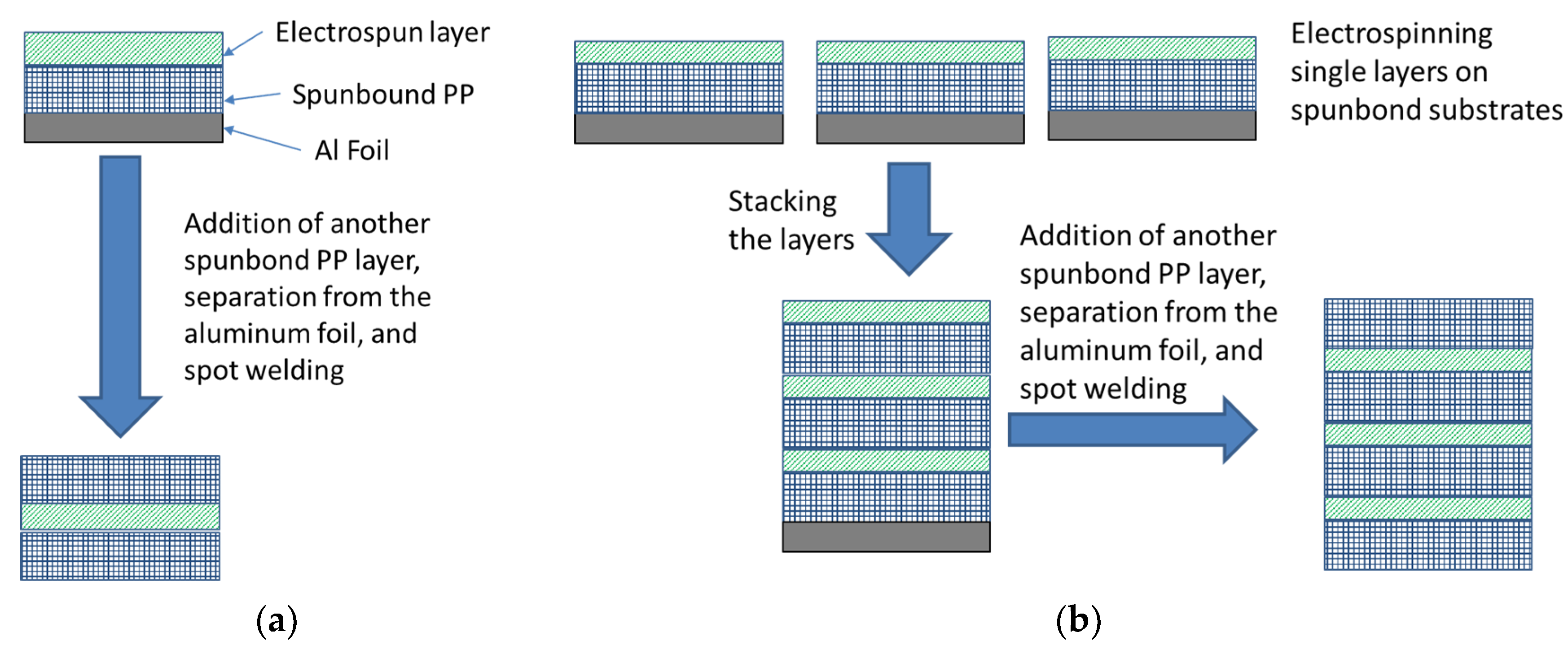
2.4. Filter Preparation

The single electrospun layer filters were fabricated by electrospinning aPVDF-HFP layer on a layer of spun-bond PP substrate (melting point 160 °C), which was placed on top of an aluminum foil on the collecting drum. Then, another spun-bond PP layer was added on top of the electrospun PVDF-HFP layer (melting point 140 °C), and all three layers were bonded using the hot spot welding process (Figure 1a). For the multi-layered structures, three electrospun layers were deposited on a spun-bond polypropylene and sandwiched with an additional spun-bond layer, as shown in Figure 1b.
Single and multilayer electrospun filters were fabricated to evaluate the effect of the layers’ arrangement and fibre structure on the air filter performance. Therefore, two single-layer filters with PLB and PHB structures were fabricated. One of the single layers was fabricated using 60% DMF-40% acetone solvent and deposited on a PP spunbond layer for 39 min and labelled PLB-39, as shown in Figure 1a. For the second single layer, 80% DMF-20% acetone solvent was used and deposited on a PP spunbond layer for 39 min and labelled PHB-39. Both of the single-layer depositions had basis weight of 0.913 ± 0.055 g/m2. The multilayer PVDF-HFP electrospun filters were deposited on three separate spunbond PP layers for 13 min using 60% DMF-40% acetone solvent. Then, the three layers were assembled as shown in Figure 1b and labelled as PLB-13-3L with a total electrospun basis weight of 1.032 ± 0.090 g/m2. Therefore, the single and multilayer air filters have almost the same basis weight. The filtering test results were compared with a commercial N95 air filter, a double layer, and a PP spunbond substrate (P0).

2.5. Characterization of Fabricated Electrospun Mats

The filtering efficiency and pressure drop of the fabricated air filters were conducted at the Department of Physics and Atmospheric Science at Dalhousie University. The details of the setup are published in [36]. The filter was held by a stainless steel assembly (Pall 1209) to expose a circular section of 25 mm diameter to the NaCl aerosol. A flow of NaCl aerosol was generated, neutralized, and passed the filter sample with a flow rate of 2.2 L/min. The filtering efficiency was measured through sampling from the upstream and downstream flows. The samples were evaluated by a Scanning Mobility Particle Size (SMPS) Spectrometer consisting of a Condensation Particle Counter (TSI-3772) and an Electrostatic Classifier (TSI-3082), which measured the particle size distribution of NaCl aerosols. The particle size range of 20–450 nm was measured to analyze the fabricated samples’ filtering performance. The following equation was used to calculate the filtering efficiency for a specific particle size (ηs):
η s = c u c d c u × 100 %
where cu and cd are the concentration of specific sizes of NaCl particles in upstream and downstream flows, respectively.
For calculation of the overall efficiency, all the size-resolved particle concentration measurements were integrated to obtain the total particle concentration in the size range of 20–450 nm for both upstream and downstream flows. Then, the overall efficiency η was calculated from the following relation:
η = N u N d N u × 100 %
where Nu and Nd are the total particle concentration in the range of 20–450 nm in upstream and downstream flows, respectively.
The pressure drop (∆P) between the upstream and downstream flows was measured by a differential manometer (Model 223BD-AAU;MKS). The formula used to calculate the quality factor (QF) is as follows:
Q F = l n ( 1 η ) Δ P
All SEM samples were prepared from the center of the fabricated mats. The samples were gold-coated before SEM examination.
ImageJ software (1.8.0) was used to measure fibre size, bead size, and bead density.

3. Results and Discussion

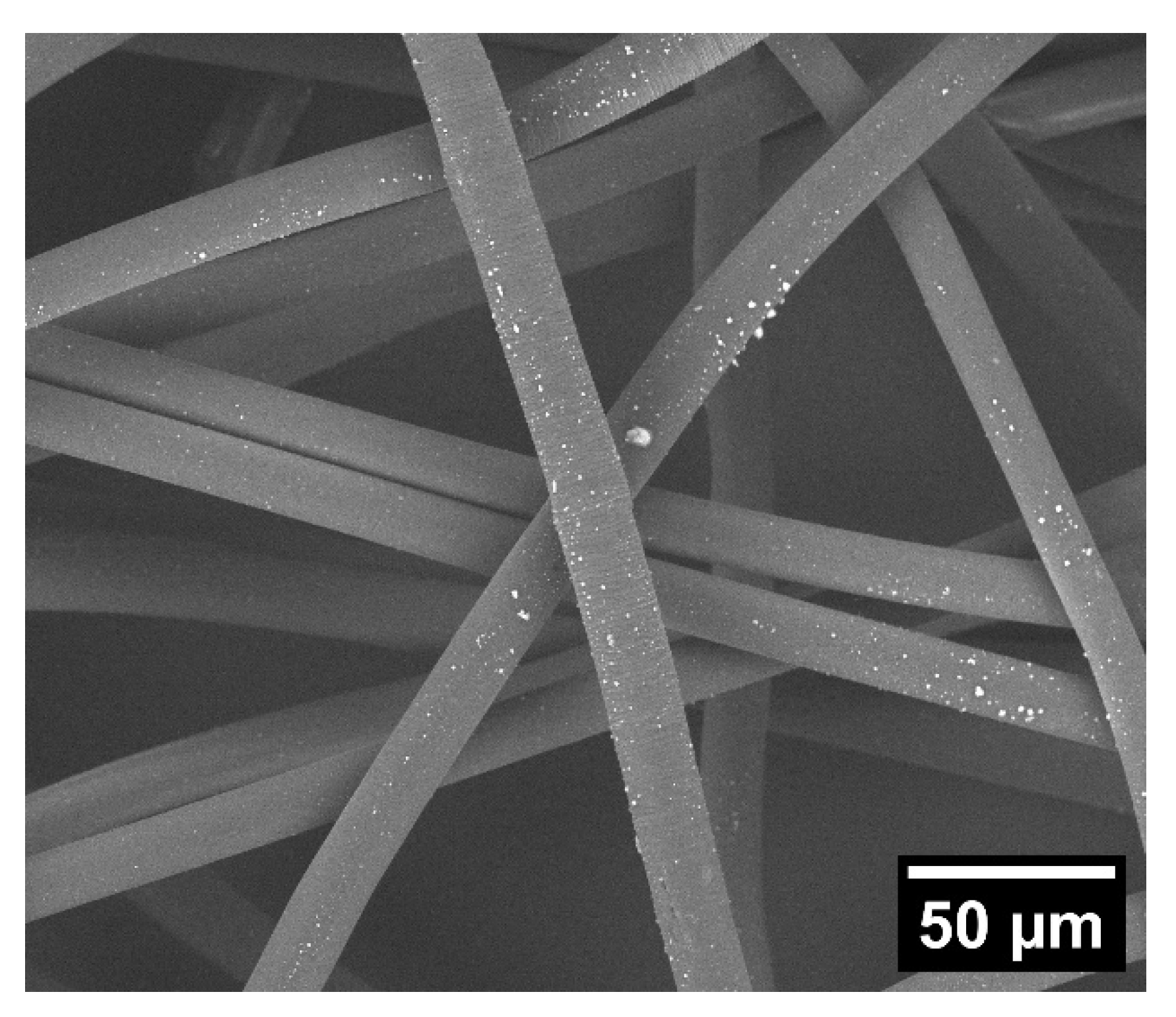
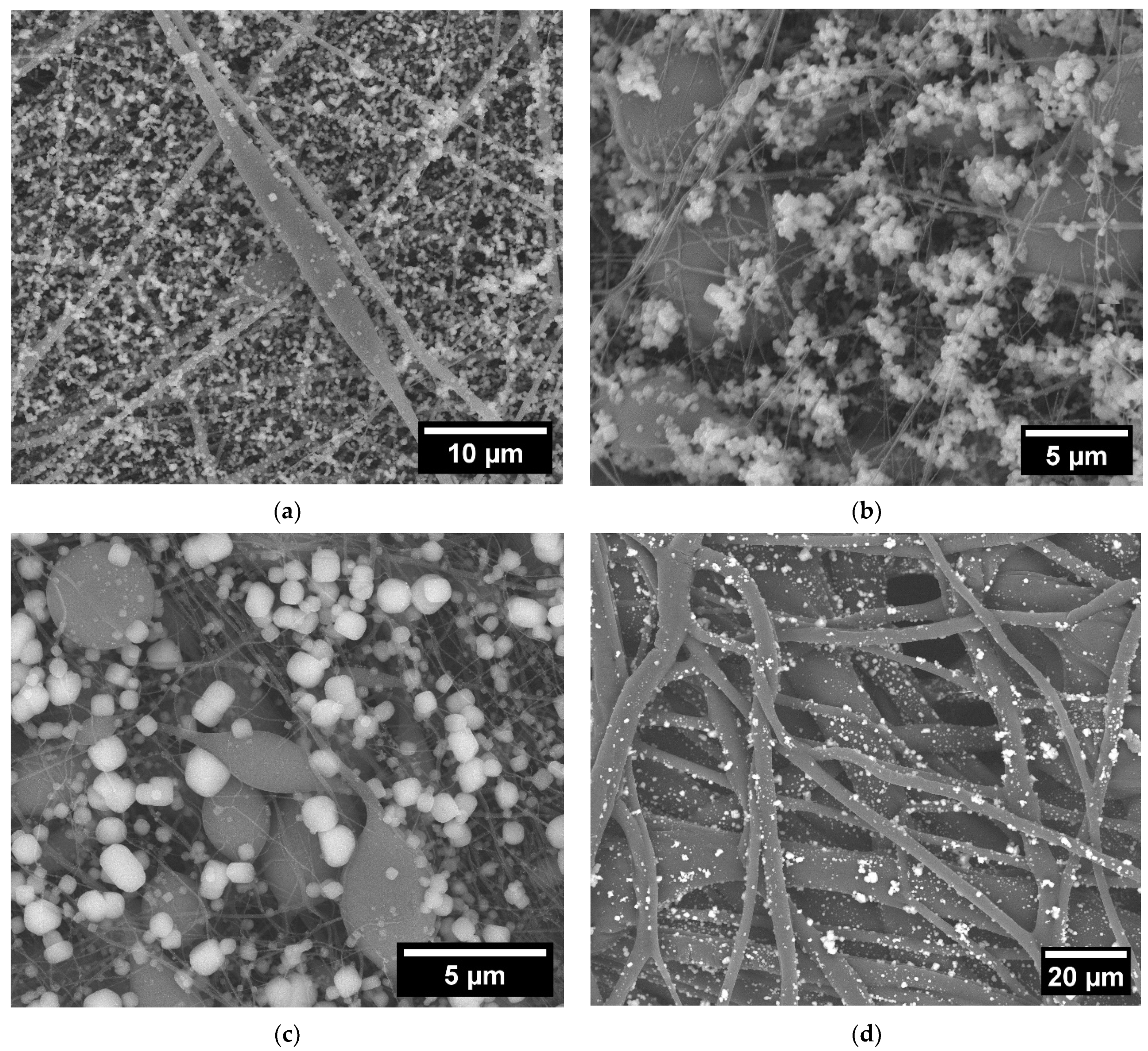
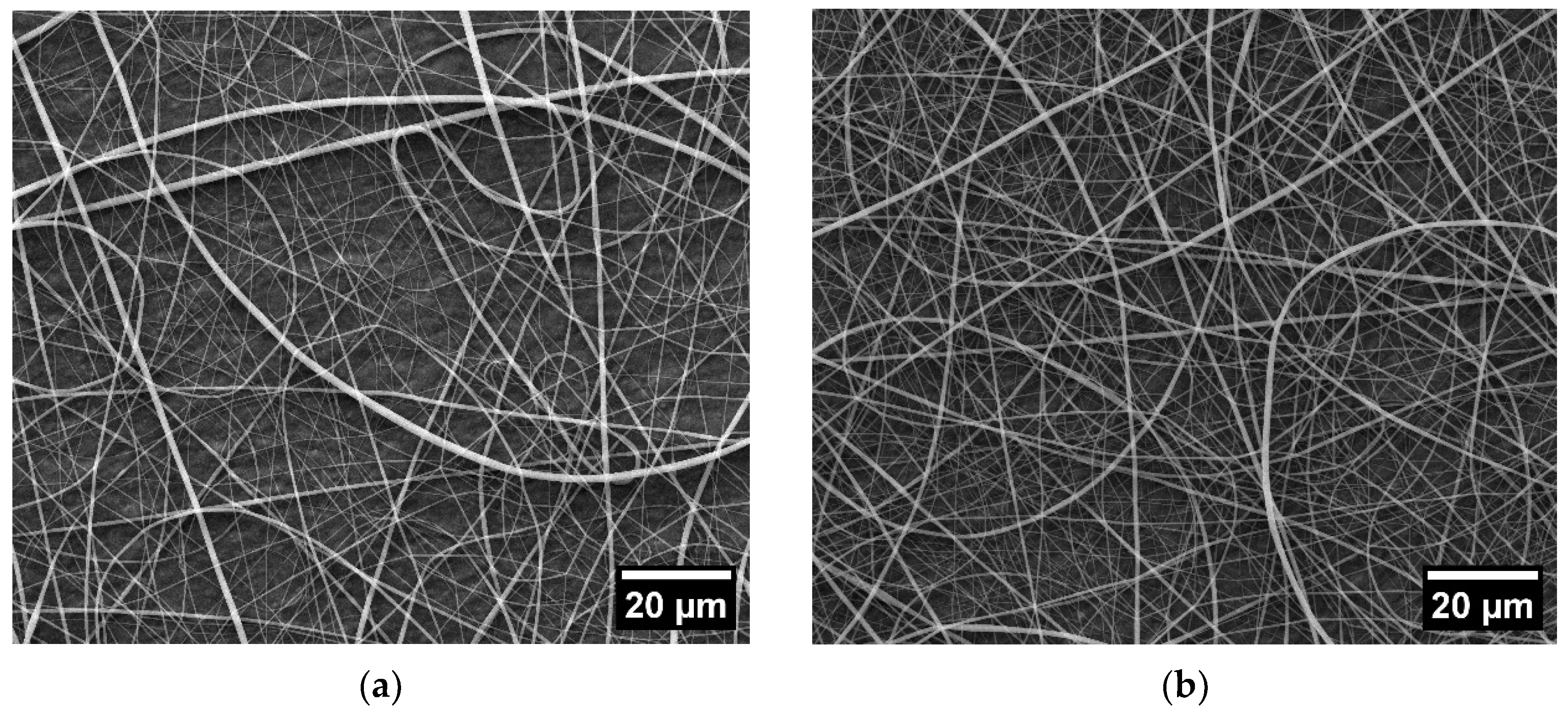
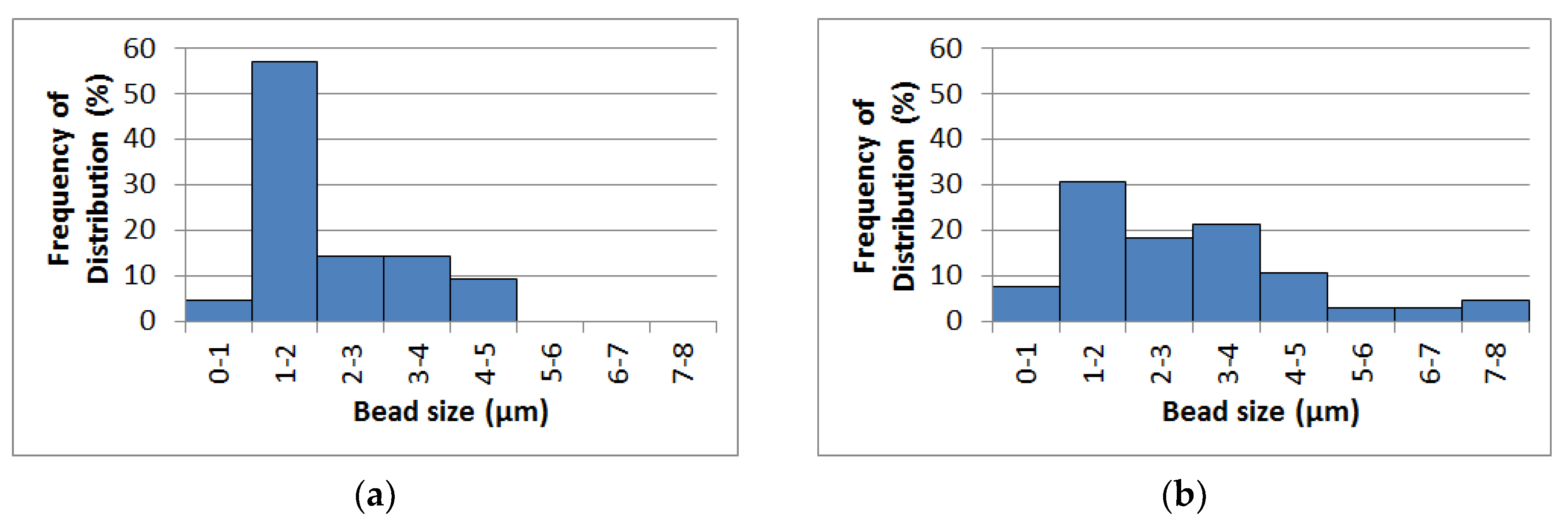
3.1. Characterization of Electrospun Fibres

For the electrospinning of PVDF-HFP, the recommended mixture of DMF–acetone was used [37,38,39,40,41,42,43,44].
Figure 2 shows the SEM images of electrospun PVDF-HFP fibres at 40% to 100% DMF concentrations. Figure 3 shows the fibre size distribution of the corresponding microstructures. As can be seen in Figure 2a,b, when 40% DMF-60% acetone and 50% DMF-50% acetone were applied as the solvent, smooth bead-free fibres were obtained with a wide range of size distribution (Figure 3a,b). However, under these conditions, the electrospinning process was not stable and frequent clogging occurred. Therefore, bead-free structures were not included in the filtration studies. By applying DMF concentrations of 60% or more, beads appeared in the morphology of the nanofibres due to the increase in solution viscosity (Figure 2c–e). The beads’ morphology changed from spindle-like at a concentration of 60% DMF to a spherical and spindle-like combination at DMF concentrations higher than 80% and 100%.
The presence of the beads usually influences the average fibre size [45,46]. Fibre diameters containing beads were reported to be smaller than bead-free fibres because of the capillary breakup [47]. As shown in Figure 2f, the average fibre size is not changed significantly at DMF concentrations between 40% and 50%. However, when beads emerged in the microstructure, the average size of the fibres was reduced. By increasing the DMF concentration in the solvent, a narrower range of fibre size distribution was formed (Figure 3). For example, the fibre diameter for 40% DMF solvent was between 150 and 1400 nm (Figure 3a). At higher DMF concentrations, the range of fibre diameter was reduced (Figure 3b,e), and at 100% DMF solvent, the fibres’ diameters were between 20 and 175 nm.
Figure 4 shows the bead size distributions and bead density for the electrospun microstructures, which were produced from solutions containing 60% or more DMF in their solvent. As seen in Figure 4d, the number of beads in the microstructures increased by increasing the concentration of DMF. However, the size and size range of the beads increased by increasing the DMF concentration from 60% to 80%, and then these two parameters were decreased with a further increase of DMF to 100% (Figure 4a–c).
The introduction of acetone to the solvent reduced the surface tension and the boiling temperature of the solution at the same time [47]. While the former reduced the tendency for bead formation, the latter increased the drying rate of the flying fibres. Therefore, large beads had less chance to divide into smaller beads on a new string called secondary beads, as shown in Figure 5 [48]. On the other hand, in the 100% DMF solution, the beads had enough time to divide and form smaller beads on the string. Therefore, the number of beads was increased, and the size of the beads and the fibre diameter were decreased. It is noteworthy that beads in nanofibres have been considered defects for many applications. However, in the case of air filter applications, they can be beneficial because they prevent the high packing density of the nonwoven layers and reduce the pressure drop of the air filters [49].
Figure 6 shows the water contact angle on the electrospun PVDF-HFP layers to evaluate their hydrophobicity. Figure 6a shows the effect of electrospinning time on the water contact angle for electrospun PLB fibres. At zero time, the contact angle of 107° is measured on the substrate PP layer. It shows that by applying PLB electrospun fibres for 13 min, the contact angle increases to 129° and reaches 131° after 90 min of electrospinning. Figure 6b shows the effect of bead content of the electrospun microstructure (PLB, PHB, and PUB) on the water contact angle after 90 min of electrospinning. By increasing the bead content of the electrospun layers, the water contact angle increases to a maximum of 135° for the PUB structure. Then, the examined bead structures show a water contact angle between 131° and 135°, which provides high hydrophobicity for the fabricated filters. Therefore, when the contact angle was measured on the surface of the electrospun layer, the number of fibres or time taken to produce the filter layer showed a small influence on the resultant contact angle measured.

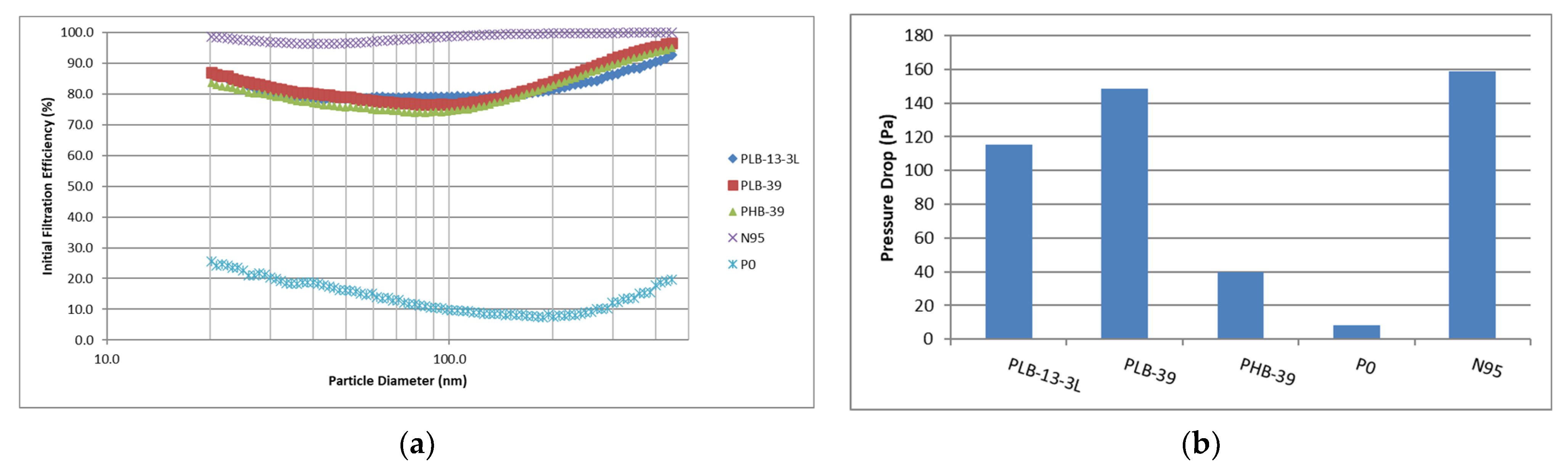
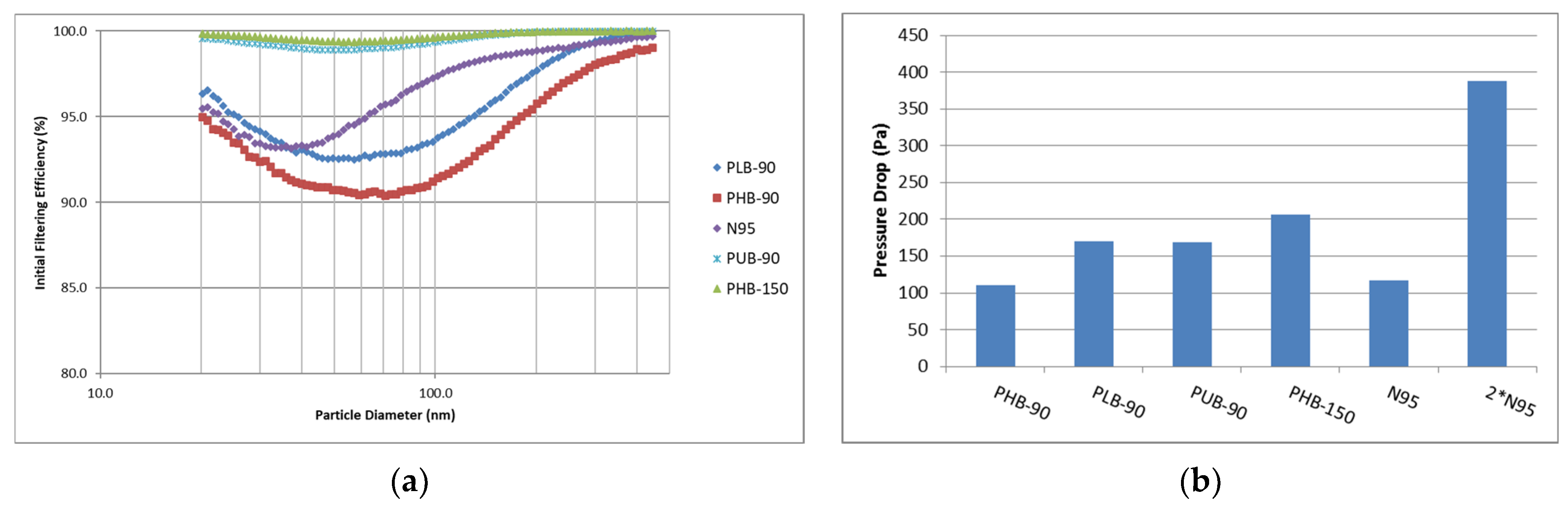
3.2. Filtering Tests

Several techniques have been proposed to reduce air filter pressure drops and enhance the quality factor. One of them is providing a multi-layered structure. It is reported that applying a multi-layered structure reduced the pressure drop effectively, and the quality factor of the air filter was improved remarkably [1,50]. Promoting the formation of beads is another method to reduce pressure drop, which researchers have used widely [49,51,52]. These two strategies can modify the air filters’ packing density, enhancing their breathability. However, it has not been reported which strategy can be more effective.
The filtering performance is shown in Table 1 and Figure 7. Table 1 shows that the efficiencies of PLB-13-3L and PLB-39 are almost the same (79.63 and 79.55%, respectively), while PHB-39 has a slightly lower efficiency of 77.38%, and the P0 sample, which contained no electrospun layers, has the efficiency of 12.97%. All three samples show similar size-resolved filtering efficiency, as shown in Figure 7a. The SEM micrograph of P0 (the spunbond layer), shown in Figure 8, also reveals that the fibres captured very few NaCl particles. Large-size neutral fibres ( 16.68 ± 1.69   μ m ) caused a low filtering performance (Figure 7a and Figure 8). Therefore, the spunbond PP layer has a negligible influence on the efficiency of the prepared samples.
On the other hand, the difference in the pressure drop between the PLB-39, PLB-13-3L, and PHB-39 samples is considerable (Figure 7b and Table 1). The PLB-39 sample shows a high-pressure drop of 148.6 Pa and a quality factor of 10.6 × 10 3   P a 1 . Applying the layered structure reduced the pressure drop, which increased the quality factor to 13.8 × 10 3   P a 1 . However, changing the microstructure of the electrospun fibres by forming the beads (PHB-39) reduced the pressure drop to less than one-third of the PLB-39 sample (40 Pa). Although such morphology shifting decreased the filtering efficiency slightly, the quality factor increased to 37.1 × 10 3   P a 1 due to the reduction in pressure drop. The large beads in PHB-39 fibres modified the packing density of the deposited electrospun layer, while inserting PP spunbond layers between the electrospun layers could modify the stacking density only between the spunbond–electrospun interfaces. Therefore, a highly beaded structure improves the air filter’s performance more effectively than applying a layered structure.
Figure 9 shows the filtering efficiency of PLB, PHB, and PUB filters. The PHB-150 was electrospun for 150 min (basis weight of 4.326 ± 0.183   g / m 2 ) and each of the other samples was electrospun for 90 min (with the electrospun basis weight of 2.40   ±   0.246   g / m 2 ). Figure 9a shows that both PHB-90 and PLB-90 have lower filtering efficiency than N95, and PHB-90 shows slightly lower filtering efficiency than PLB-90. However, Figure 9b shows that the pressure drop of PLB-90 is higher than PHB-90, which caused the quality factor of PHB-90 to be considerably higher than PLB-90 (Table 2). For PUB-90, the filtering efficiency increased to 99.32%, higher than PHB-90 (92.26%) and PLB-90 (94.2%). The pressure drop of PUB-90 was closer to PLB-90, which was far higher than PHB-90 (Figure 9b).
The efficiency reduction of PHB-90 compared with PUB-90 and PLB-90 is due to the bead structure of the samples. Figure 10 shows the absorption of NaCl particles with the surface of the electrospun fibres after the filtering test and indicates that the beads captured very few salt particles. Therefore, the beads’ presence could modify the filters’ packing density and reduce the air pressure drop, but they did not contribute to capturing the particles. Large spherical beads were developed in PHB samples, which simultaneously reduced the packing density and fibre size. Since large beads consumed much material without significantly contributing to particle absorption, they negatively impacted the efficiency of the air filter.
On the other hand, beads significantly reduced the average fibre size, increasing the available surface and enhancing Van der Waals’s force simultaneously. As a result, the formed fibres could be more effective at the absorption of small particles [52]. It seemed for PHB samples. The former effect overcame the latter in comparison with PLB and PUB samples.
For PLB samples, both sizes of beads and their numbers were relatively small (Figure 2a and Figure 4a,d). Although the average fibre size of PLB is larger than PHB (Figure 2f), most of the polymer is available in fibre, which can absorb NaCl particles effectively but offers lower breathability (high-pressure drop).
In PUB samples, large beads were divided into smaller secondary beads based on the schematic in Figure 5, and each division formed a small string. As a result, some parts of the large beads were consumed to form new fibres. Additionally, the average fibre size was reduced significantly (Figure 2f). Therefore, the filtering efficiency of PUB is enhanced. The presence of numerous small beads in the PUB structure also reduced the pressure drop of the air filters. As a result, the quality factor of the air filter improved significantly.
Increasing the electrospinning time from 90 min to 150 min could improve the filtering efficiency of the PHB filter to 99.61%, which was slightly higher than PUB-90 (99.32%). However, the pressure drop of PHB-150 (206 Pa) was higher than PUB-90 (169 Pa), leading to a slightly lower quality factor ( 26.9 × 10 3   P a 1 ) for PHB-150 compared with 28.7 × 10 3   P a 1 for PUB-90. Since PUB-90 requires less electrospinning time (higher production rate) and offers a better quality factor, it will be more appropriate for large-scale production.
Standard N95 air filters were also tested as the reference in this study. In all cases, their MPPS was 30–40 nm, less than the reported size for SARS-CoV-2 virions (60–150 nm) [53]. It is noteworthy that the size of bioaerosols is almost always larger than the virions [1]. Also, the overall efficiencies of tested N95 air filters were more than 95%, and in most cases, their MPPS was 95.5%. However, the MPPS for PUB-90 and PHB-150 (electrospun samples) were slightly higher (50–60 nm), and their filtering efficiencies at their MPPS were 98.91% and 99.36%, respectively, as shown in Figure 11 and Table 2. Therefore, PUB-90 and PHB-150 could provide superior filtering efficiency compared to N95 air filters.
Comparison between the interaction of NaCl particles with the N95 sample and both electrospun filters (PUB-90 and PHB-150) reveals that most of the NaCl particles were absorbed on the surface of the electrospun filters. However, a small fraction of them was absorbed on the surface of the N95 masks (Figure 10). Therefore, the electrospun samples show surface filtration, which is typical for nanofibres, whereas the N95 filter shows in-depth filtration. As a result, the electrospun samples can continue to remove the particles effectively for a longer time [54].

4. Conclusions

Electrospun PVDF-HFP was used to fabricate air filters and investigate the effect of fibre bead content and layered structure on the filtering performance. The main conclusions are summarized as follows:
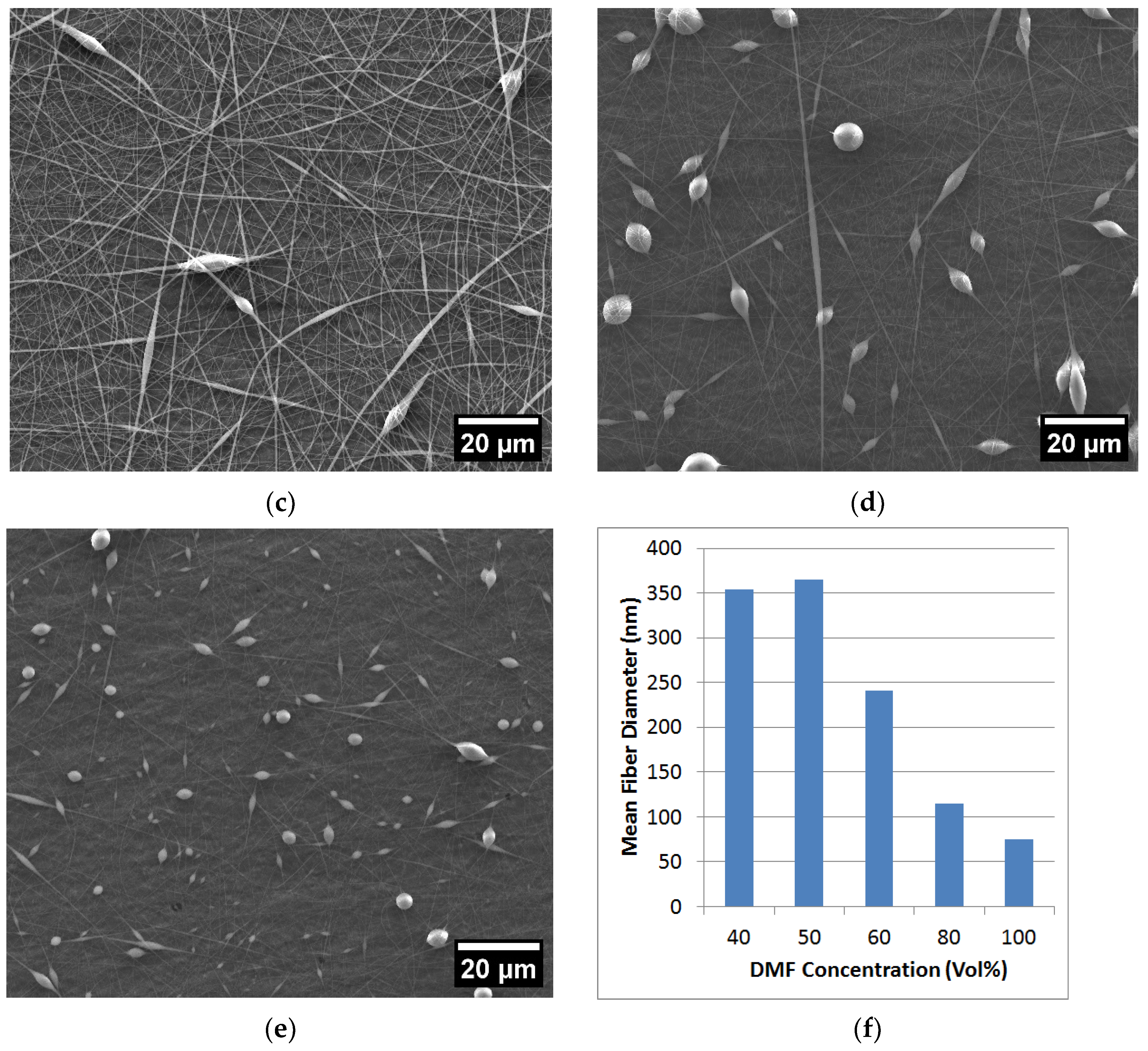
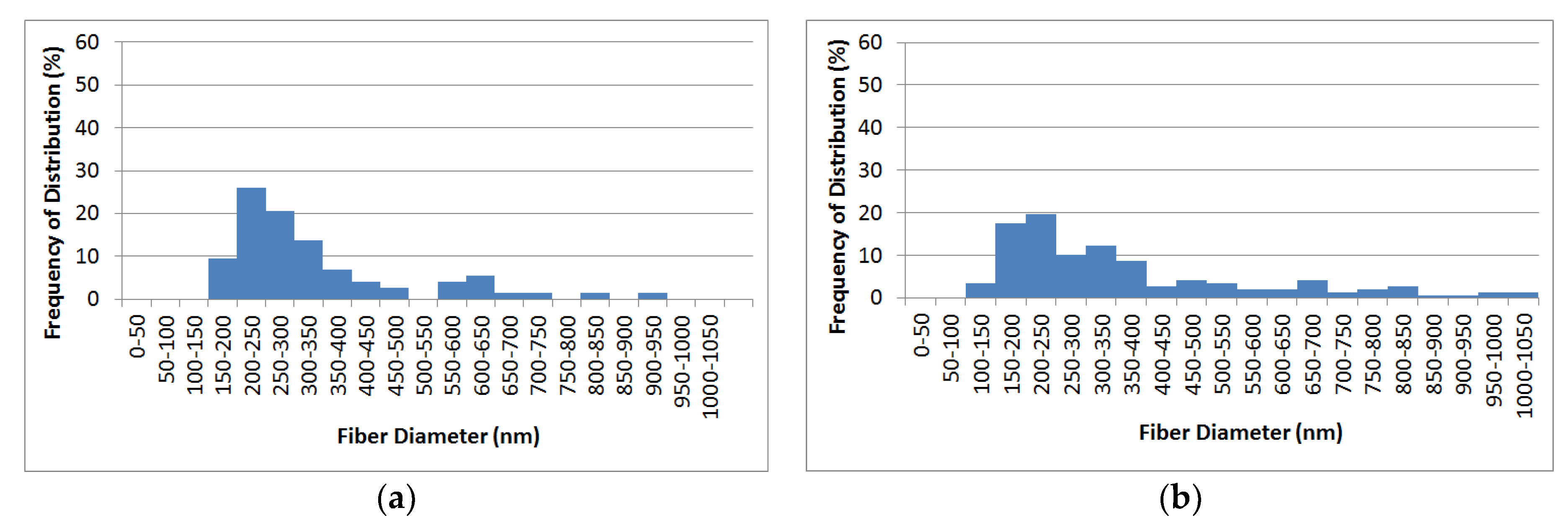
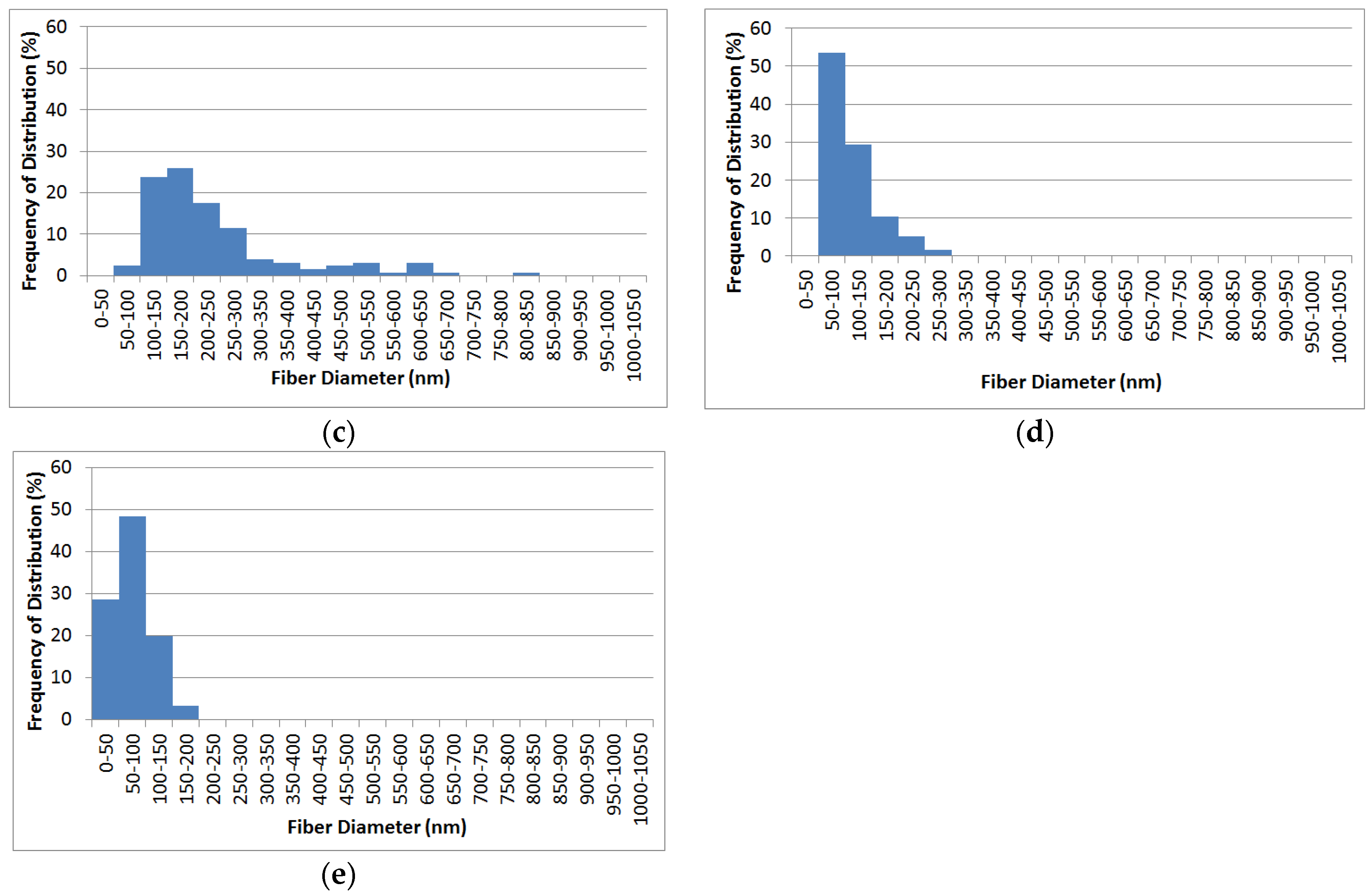
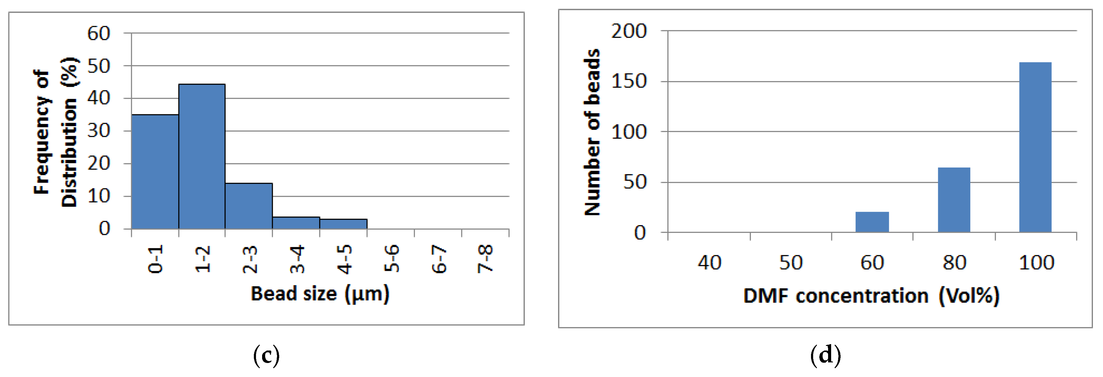
  • Bead-free, low-bead, high-bead and ultra-high-bead PVDF-HFP electrospun fibres were produced by changing the DMF to acetone ratio in the polymer solvent. At DMF concentrations above 50%, beads appeared in the electrospun fibres. Increasing the DMF concentration increased the bead density but decreased the fibre size;
  • Applying electrospun PVDF-HFP layers on a PP spunbond substrate enhanced the hydrophobicity;
  • Both the multi-layered design and a higher density of beads on the fibres decrease the pressure drop across the filter, thereby improving the air filter quality factor;
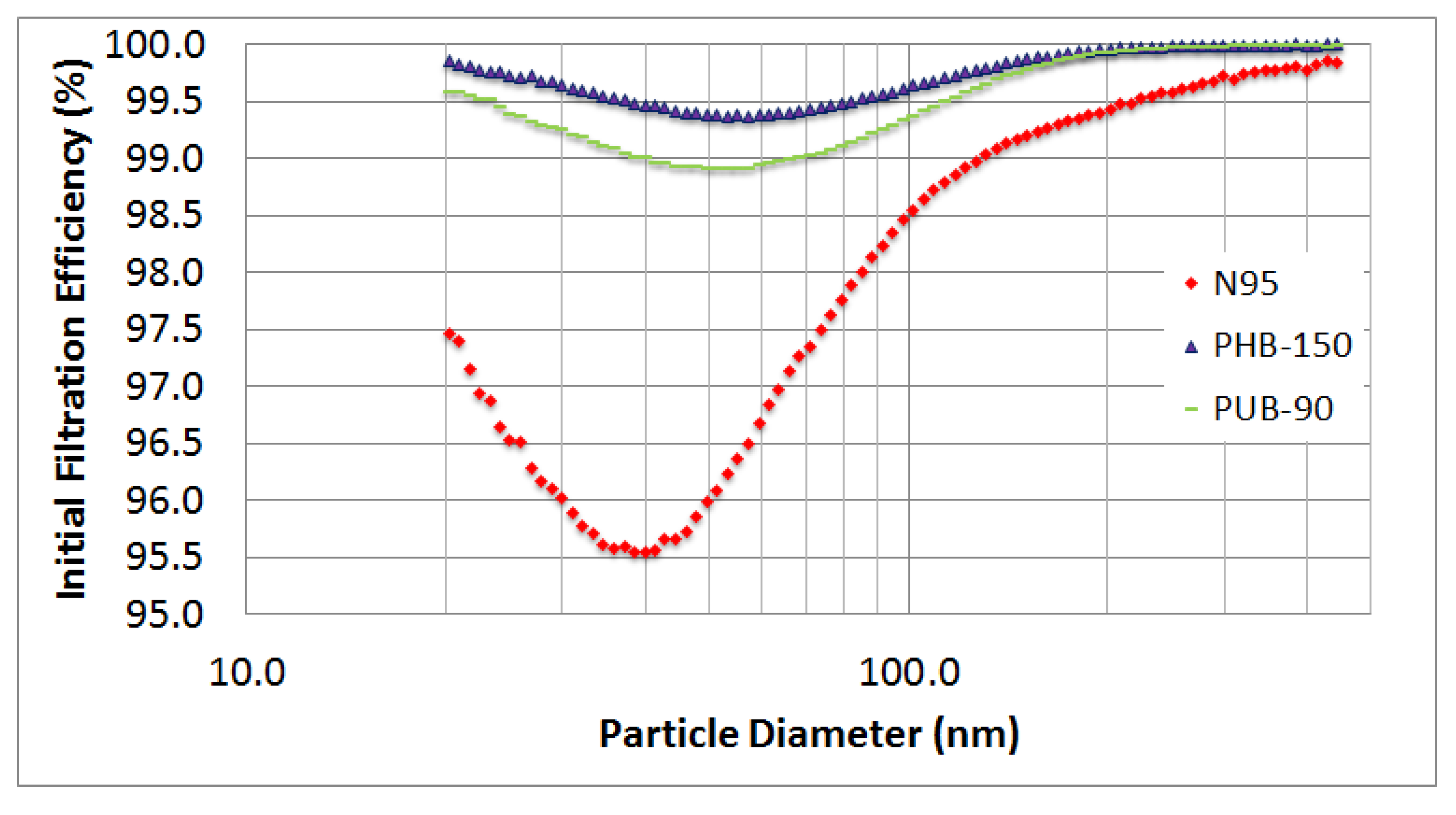
  • The optimum performance was achieved by the PUB-90 air filter with an overall efficiency of 99.33% and a quality factor of 27.6 × 10 3   P a 1 , superior to the N95 air filter compared to double N95.

Author Contributions

Conceptualization, R.A.R.; Methodology, I.A.B. and R.A.R.; Software, M.S.; Validation, M.S.; Formal analysis, C.B.; Investigation, G.G.; Writing—original draft, I.A.B.; Writing—review & editing, A.J.; Supervision, R.A.R.; Project administration, R.A.R.; Funding acquisition, R.A.R. All authors have read and agreed to the published version of the manuscript.

Funding

This research was funded by the Natural Sciences and Engineering Research Council of Canada (NSERC) Alliance COVID-19 and Discovery Grant.

Data Availability Statement

The authors declare that the data support the findings of this study and are included in this published article.

Acknowledgments

Financial support for this research was provided by the Natural Sciences and Engineering Research Council of Canada (NSERC). The authors would like to gratefully acknowledge Sharon Lackie of the Great Lakes Institute for Environmental Research (GLIER), University of Windsor, Windsor, ON, for her assistance with the SEM micrographs.

Conflicts of Interest

The authors declare no conflict of interest. The funders had no role in the design of the study; in the collection, analyses, or interpretation of data; in the writing of the manuscript; or in the decision to publish the results.

References

  1. Leung, W.W.; Sun, Q. Charged PVDF multilayer nanofiber filter in filtering simulated airborne novel coronavirus (COVID-19) using ambient nano-aerosols. Sep. Purif. Technol. 2020, 245, 116887. [Google Scholar] [CrossRef]
  2. Chen, N.; Zhou, M.; Dong, X.; Qu, J.; Gong, F.; Han, Y.; Qiu, Y.; Wang, J.; Liu, Y.; Wei, Y.; et al. Epidemiological and clinical characteristics of 99 cases of 2019 novel coronavirus pneumonia in Wuhan, China: A descriptive study. Lancet 2020, 395, 507–513. [Google Scholar] [CrossRef] [PubMed]
  3. Karimzadeh, S.; Bhopal, R.; Tien, H.N. Review of infective dose, routes of transmission and outcome of COVID-19 caused by the SARS-CoV-2: Comparison with other respiratory viruses. Epidemiol. Infect. 2021, 149, 96. [Google Scholar] [CrossRef] [PubMed]
  4. Rasmussen, A.L.; Escandón, K.; Popescu, S.V. Facial masking for COVID-19. N. Engl. J. Med. 2020, 383, 2092. [Google Scholar] [PubMed]
  5. Liang, M.; Gao, L.; Cheng, C.; Zhou, Q.; Uy, J.P.; Heiner, K.; Sun, C. Efficacy of face mask in preventing respiratory virus transmission: A systematic review and meta-analysis. Travel Med. Infect. Dis. 2020, 36, 101751. [Google Scholar] [CrossRef]
  6. Geus, H.G. Developments in manufacturing techniques for technical nonwovens. In Advances in Technical Nonwovens, 1st ed.; Kellie, G., Ed.; Elsevier Inc.: Amsterdam, The Netherlands, 2016; Volume 1, pp. 133–153. [Google Scholar]
  7. Saleem, H.; Trabzon, L.; Kilic, A.; Zaidi, S.J. Recent advances in nanofibrous membranes: Production and applications in water treatment and desalination. Desalination 2020, 478, 114178. [Google Scholar] [CrossRef]
  8. Kilic, A.; Russell, S.; Shim, E.; Pourdeyhimi, B. The charging and stability of electret filters. Fibrous Filter Media 2017, 1, 95–121. [Google Scholar]
  9. Borojeni, I.A.; Gajewski, G.; Riahi, A.R. Application of Electrospun Nonwoven Fibers in Air Filters-Review. Fibers 2022, 10, 15. [Google Scholar] [CrossRef]
  10. Haider, A.; Haider, S.; Kang, I.K. A comprehensive review summarizing the effect of electrospinning parameters and potential applications of nanofibers in biomedical and biotechnology. Arab. J. Chem. 2018, 11, 1165–1188. [Google Scholar] [CrossRef]
  11. Reneker, D.H.; Yarin, A.L. Electrospinning jets and polymer nanofibers. Polymer 2008, 49, 2387–2425. [Google Scholar] [CrossRef]
  12. Bhardwaj, N.; Kundu, S.C. Electrospinning: A fascinating fiber fabrication technique. Biotechnol. Adv. 2010, 28, 325–347. [Google Scholar] [CrossRef] [PubMed]
  13. Mokhtari, F.; Salehi, M.; Zamani, F.; Hajiani, F.; Zeighami, F.; Latifi, M. Advances in electrospinning: The production and application of nanofibres and nanofibrous structures. Text. Prog. 2016, 48, 119–219. [Google Scholar] [CrossRef]
  14. Zhang, S.; Rind, N.A.; Tang, N.; Liu, H.; Yin, X.; Yu, J.; Ding, B. Electrospun nanofibers for air filtration. In Electrospinning: Nanofabrication and Applications, 1st ed.; Ding, B., Wang, X., Yu, J., Eds.; Elsevier Inc.: Amsterdam, The Netherlands, 2019; Volume 1, pp. 365–389. [Google Scholar]
  15. Collins, G.; Federici, J.; Imura, Y.; Catalani, L.H. Charge generation, charge transport, and residual charge in the electrospinning of polymers: A review of issues and complications. J. Appl. Phys. 2012, 111, 044701. [Google Scholar] [CrossRef]
  16. Roche, R.; Yalcinkaya, F. Electrospun polyacrylonitrile nanofibrous membranes for point-of-use water and air cleaning. Chem. Open 2019, 8, 97. [Google Scholar] [CrossRef] [PubMed]
  17. Huang, J.J.; Tian, Y.; Wang, R.; Tian, M.; Liao, Y. Fabrication of bead-on-string polyacrylonitrile nanofibrous air filters with superior filtration efficiency and ultralow pressure drop. Sep. Purif. Technol. 2020, 237, 116377. [Google Scholar] [CrossRef]
  18. Vinh, N.D.; Kim, H.M. Electrospinning fabrication and performance evaluation of polyacrylonitrile nanofiber for air filter applications. Appl. Sci. 2016, 6, 235. [Google Scholar] [CrossRef]
  19. Wang, S.; Zhao, X.; Yin, X.; Yu, J.; Ding, B. Electret polyvinylidene fluoride nanofibers hybridized by polytetrafluoroethylene nanoparticles for high-efficiency air filtration. ACS Appl. Mater. Interfaces 2016, 8, 23985–23994. [Google Scholar] [CrossRef]
  20. Li, X.; Wang, C.; Huang, X.; Zhang, T.; Wang, X.; Min, M.; Wang, L.; Huang, H.; Hsiao, B.S. Anionic surfactant-triggered steiner geometrical poly (vinylidene fluoride) nanofiber/nanonet air filter for efficient particulate matter removal. ACS Appl. Mater. Interfaces 2018, 10, 42891–42904. [Google Scholar] [CrossRef]
  21. Ding, X.; Li, Y.; Si, Y.; Yin, X.; Yu, J.; Ding, B. Electrospun polyvinylidene fluoride/SiO2 nanofibrous membranes with enhanced electret property for efficient air filtration. Compos. Commun. 2019, 13, 57–62. [Google Scholar] [CrossRef]
  22. Liu, H.; Zhang, S.; Liu, L.; Yu, J.; Ding, B. Anionic surfactant PM0.3 Air Filters Using Self-Polarized Electret Nanofiber/Nets. Adv. Funct. Mater. 2020, 30, 1909554. [Google Scholar] [CrossRef]
  23. Kang, G.D.; Cao, Y.M. Application and modification of poly (vinylidene fluoride)(PVDF) membranes—A review. J. Membr. Sci. 2014, 463, 145–165. [Google Scholar] [CrossRef]
  24. Liu, F.; Hashim, N.A.; Liu, Y.; Abed, M.M.; Li, K. Progress in the production and modification of PVDF membranes. J. Membr. Sci. 2011, 375, 1–27. [Google Scholar] [CrossRef]
  25. Lolla, D.; Lolla, M.; Abutaleb, A.; Shin, H.U.; Reneker, D.H.; Chase, G.G. Fabrication, polarization of electrospun polyvinylidene fluoride electret fibers and effect on capturing nanoscale solid aerosols. Materials 2016, 9, 671. [Google Scholar] [CrossRef] [PubMed]
  26. Zaarour, B.; Tina, H.; Zhu, L.; Jin, X. Branched nanofibers with tiny diameters for air filtration via one-step electrospinning. J. Ind. Text. 2020, 51, 1105S–1117S. [Google Scholar] [CrossRef]
  27. Cui, Z.; Drioli, E.; Lee, Y.M. Recent progress in fluoropolymers for membranes. Prog. Polym. Sci. 2014, 39, 164–198. [Google Scholar] [CrossRef]
  28. Lee, J.S.; Kim, H.J.; Jung, S.; Kim, J.; Lee, M.W. Repair of Disposable Air Filters by Solution-Blown Nano/Micro Fibrous Patches. ACS Appl. Nano Mater. 2020, 11, 11344–11351. [Google Scholar] [CrossRef]
  29. Macevele, L.E.; Kgabo, L.; Moganedi, M.; Magadzu, T. Investigation of Antibacterial and Fouling Resistance of Silver and Multi-Walled Carbon Nanotubes Doped Poly(Vinylidene Fluoride-co-Hexafluoropropylene) Composite Mem-brane. Membranes 2017, 7, 35. [Google Scholar] [CrossRef]
  30. Ganesh, V.A.; Kundukad, B.; Cheng, D.; Radhakrishnan, S.; Ramakrishna, S.; Van Vliet, K.J. Engineering silver-zwitterionic composite nanofiber membrane for bacterial fouling resistance. J. Appl. Polym. Sci. 2019, 136, 47580. [Google Scholar] [CrossRef]
  31. Wang, X.; Xiao, C.; Liu, H.; Chen, M.; Xu, H.; Luo, W.; Zhang, F. Robust functionalization of underwater superoleophobic PVDF-HFP tubular nanofiber membranes and applications for continuous dye degradation and oil/water separation. J. Membr. Sci. 2020, 596, 117583. [Google Scholar] [CrossRef]
  32. Chen, J.P.; Guo, C.Y.; Zhang, Q.J.; Wu, X.Q.; Zhong, L.B.; Zheng, Y.M. Preparation of transparent, amphiphobic and recyclable electrospun window screen air filter for high-efficiency particulate matters capture. J. Membr. Sci. 2023, 675, 121545. [Google Scholar] [CrossRef]
  33. Cui, W.; Fan, T.; Li, Y.; Wang, X.; Liu, X.; Lu, C.; Ramakrishna, D.S.; Long, Y.Z. Ro-bust functional Janus nanofibrous membranes for efficient harsh environmental air filtration and oil/water separation. J. Membr. Sci. 2022, 663, 121018. [Google Scholar] [CrossRef]
  34. Lee, J.S.; Oh, Y.; Kim, H.; Park, H.S.; Yoon, S.S.; Lee, M.W. Performance Study of Composite Air Filters Using Heterogeneous Fibers. Compos. Res. 2022, 35, 216–221. [Google Scholar]
  35. Han, K.S.; Lee, S.; Kim, M.; Park, P.; Lee, M.H.; Nah, J. Electrically activated ultrathin PVDF-TrFE air filter for high-efficiency PM1.0 filtration. Adv. Funct. Mater. 2019, 29, 1903633. [Google Scholar] [CrossRef]
  36. Wong, D.; Hartery, S.; Keltie, E.; Chang, R.; Kim, J.S.; Park, S.S. Electrospun Polystyrene and Acid-Treated Cellulose Nanocrystals with Intense Pulsed Light Treatment for N95-Equivalent Filters. ACS Appl. Polym. Mater. 2021, 3, 4949–4958. [Google Scholar] [CrossRef]
  37. Hou, D.; Lin, D.; Ding, C.; Wang, D.; Wang, J. Fabrication and characterization of electrospun superhydrophobic PVDF-HFP/SiNPs hybrid membrane for membrane distillation. Sep. Purif. Technol. 2017, 189, 82–89. [Google Scholar] [CrossRef]
  38. Spasova, M.; Manolova, N.; Markova, N.; Rashkov, I. Superhydrophobic PVDF and PVDF-HFP nanofibrous mats with antibacterial and anti-biofouling properties. Appl. Surf. Sci. 2016, 363, 363–371. [Google Scholar] [CrossRef]
  39. Görgün, N.; Özer, Ç.; Polat, K. A new catalyst material from electrospun PVDF-HFP nanofibers by using magnetron-sputter coating for the treatment of dye-polluted waters. Adv. Compos. Hybrid Mater. 2019, 2, 423–430. [Google Scholar] [CrossRef]
  40. Khajavi, R.; Abbasipour, M. Controlling nanofiber morphology by the electrospinning process. Electrospun Nanofibers 2017, 1, 109–123. [Google Scholar]
  41. Jeong, H.S.; Noh, J.H.; Hwang, C.G.; Kim, S.H.; Lee, S.Y. Effect of Solvent–Nonsolvent Miscibility on Morphology and Electrochemical Performance of SiO2/PVdF-HFP-Based Composite Separator Membranes for Safer Lithium-Ion Batteries. Macromol. Chem. Phys. 2010, 211, 420–425. [Google Scholar] [CrossRef]
  42. Cardea, S.; Baldino, L.; Reverchon, E. Comparative study of PVDF-HFP-curcumin porous structures produced by supercritical assisted processes. J. Supercrit. Fluids 2018, 133, 270–277. [Google Scholar] [CrossRef]
  43. Wu, L.; Huang, G.; Hu, N.; Fu, S.; Qiu, J.; Wang, Z.; Ying, J.; Chen, Z.; Li, W.; Tang, S. Improvement of the piezoelectric properties of PVDF-HFP using AgNWs. RSC Adv. 2014, 4, 35896–35903. [Google Scholar] [CrossRef]
  44. Koh, M.J.; Hwang, H.Y.; Kim, D.J.; Kim, H.J.; Hong, Y.T.; Nam, S.Y. Preparation and characterization of porous PVdF-HFP/clay nanocomposite membranes. J. Mater. Sci. Technol. 2010, 26, 633–638. [Google Scholar] [CrossRef]
  45. Munir, M.M.; Suryamas, A.B.; Iskandar, F.; Okuyama, K. Scaling law on particle-to-fiber formation during electrospinning. Polymer 2009, 50, 4935–4943. [Google Scholar] [CrossRef]
  46. Borojeni, I.A.; Jenab, A.; Sanjari, M.; Boudreault, C.; Klinck, M.; Strong, S.; Riahi, A.R. Effect of Nanoclay Addition on the Morphology, Fiber Size Distribution and Pore Size of Electrospun Polyvinylpyrrolidone (PVP) Composite Fibers for Air Filter Applications. Fibers 2021, 9, 48. [Google Scholar] [CrossRef]
  47. Majumder, S.; Matin, M.A.; Sharif, A.; Arafat, M.T. Understanding solubility, spinnability and electrospinning behaviour of cellulose acetate using different solvent systems. Bull. Mater. Sci. 2019, 42, 171. [Google Scholar] [CrossRef]
  48. Zhu, S.; Yu, H.; Chen, Y.; Zhu, M. Study on the morphologies and formational mechanism of poly (hydroxybutyrate-co-hydroxyvalerate) ultrafine fibers by dry-jet-wet-electrospinning. J. Nanomater. 2012, 2012, 525419. [Google Scholar] [CrossRef]
  49. Wang, Z.; Zhao, C.; Pan, Z. Porous bead-on-string poly (lactic acid) fibrous membranes for air filtration. J. Colloid Interface Sci. 2015, 441, 121–129. [Google Scholar] [CrossRef]
  50. Leung, W.W.; Hung, C.H.; Yuen, P.T. Effect of face velocity, nanofiber packing density and thickness on filtration performance of filters with nanofibers coated on a substrate. Sep. Purif. Technol. 2010, 71, 30–37. [Google Scholar] [CrossRef]
  51. Yun, K.M.; Suryamas, A.B.; Iskandar, F.; Bao, L.; Niinuma, H.; Okuyama, K. Morphology optimization of polymer nanofiber for applications in aerosol particle filtration. Sep. Purif. Technol. 2010, 75, 340–345. [Google Scholar] [CrossRef]
  52. Mao, N. Nonwoven fabric filters. In Fibrous Filter Media, 1st ed.; Brown, P., Cox, C.L., Eds.; Woodhead Publishing: Cambridge, UK, 2017; Volume 1, pp. 133–171. [Google Scholar]
  53. Scholkmann, F.; Nicholls, J. Pulmonary vascular pathology in COVID-19. N. Engl. J. Med. 2020, 383, 887–888. [Google Scholar]
  54. Nam, C.; Lee, S.; Ryu, M.; Lee, J.; Lee, H. Electrospun nanofiber filters for highly efficient PM 2.5 capture. Korean J. Chem. Eng. 2019, 36, 1565–1574. [Google Scholar] [CrossRef]
Figure 1. Schematic of air filter preparation process: (a) single-layered air filter; (b) multi-layered air filter.
Fibers 11 00071 g001
Figure 2. SEM micrographs (ae) and average fibre size (f) of electrospun PVDF-HFP from solvent compositions: (a) 40% DMF-60% acetone, (b) 50% DMF-50% acetone, (c) 60% DMF-40% acetone (PLB), (d) 80% DMF-20% acetone (PHB), (e) 100% DMF (PUB), and (f) average fibre size vs. DMF concentration in the solvent; the needle tip-collector distance was 20 cm and the electrospinning time was 5 min.
Fibers 11 00071 g002aFibers 11 00071 g002b
Figure 3. Fibre size distribution of electrospun PVDF-HFP from different solvent compositions: (a) 40% DMF-60% acetone, (b) 50% DMF-50% acetone, (c) 60% DMF-40% acetone, (d) 80% DMF-20% acetone, and (e) 100% DMF.
Fibers 11 00071 g003aFibers 11 00071 g003b
Figure 4. Bead size distribution (ac) and number of beads per unit area (d) of electrospun PVDF-HFP at different solvent compositions; (a) 60% DMF-40% acetone, (b) 80% DMF-20% acetone, (c) 100% DMF, and (d) number of beads per unit area with different concentrations of DMF (60–100%).
Fibers 11 00071 g004aFibers 11 00071 g004b
Figure 5. The mechanism for dividing the primary to secondary beads [47].
Fibers 11 00071 g005
Figure 6. Water contact angle measurements of the electrospun layers: (a) the effect of electrospinning time on the water contact angle of PLB electrospun fibres; (b) the effect of electrospun microstructure at 90 min electrospinning time.
Fibers 11 00071 g006
Figure 7. The performances of PLB-13-3L, PLB-39, PHB-39, P0, and N95 air filters: (a) the size-resolved filtering efficiency and (b) the pressure drop.
Fibers 11 00071 g007
Figure 8. Back-scattered SEM micrograph of interaction between the PP spunbond fibres (P0) with NaCl particle after the size-resolved filtering test.
Fibers 11 00071 g008
Figure 9. The performances of PBH-90, PLB-90, PUB-90, PHB-150, N95, and double N95 (2 × N95) air filters: (a) the size-resolved filtering efficiency and (b) the pressure drop.
Fibers 11 00071 g009
Figure 10. Back-scattered SEM micrographs of interaction between air filter fibres with NaCl particle after the size-resolved filtering test: (a) PLB-90, (b) PHB-90, (c) PUB-90, and (d) N95.
Fibers 11 00071 g010
Figure 11. The size-resolved filtering efficiency of PUB-90, PHB-150, and N95.
Fibers 11 00071 g011
Table 1. The filtering parameters (pressure drop, initial filtration efficiency, efficiency at Most Penetrating Particle Size, and quality factor) of PLB-13-3L, PLB-39, PHB-39, P0, and N95 air filters.
SamplePressure Drop (Pa)Initial Filtration
Efficiency (%)
Efficiency at MPPS (%)Quality Factor (Pa−1)
PLB-13-3L117.396.5495.17 28.7 × 10 3
PLB-39148.679.5676.50 10.7 × 10 3
PHB-3940.077.3773.86 37.1 × 10 3
P08.012.977.26 17.4 × 10 3
N95159.097.7496.28 23.9 × 10 3
Table 2. The filtering parameters of PBH-90, PLB-90, PUB-90, PHB-150, N95, and double N95 (2 × N95) air filters.
SamplePressure Drop (Pa)Initial Filtration Efficiency (%)Efficiency at MPPS (%)Quality Factor (Pa−1)
N95117.396.5495.17 28.7 × 10 3
2×N95388.099.8699.65 16.9 × 10 3
PHB-90110.792.2690.50 21.3 × 10 3
PLB-90170.694.2192.50 15.2 × 10 3
PUB-90169.399.3398.91 27.6 × 10 3
PHB-150206.699.6199.36 26.9 × 10 3
Disclaimer/Publisher’s Note: The statements, opinions and data contained in all publications are solely those of the individual author(s) and contributor(s) and not of MDPI and/or the editor(s). MDPI and/or the editor(s) disclaim responsibility for any injury to people or property resulting from any ideas, methods, instructions or products referred to in the content.

