Abstract
Friction and wear become significant at small scale lengths, particularly in MEMS/NEMS. Nanopatterns are regarded as a potential approach to solve these problems. In this paper, we investigated the friction behavior of nanopatterned silicon surfaces with a periodical rectangular groove array in dry and wear-less single-asperity contact at the nanoscale using molecular dynamics simulations. The synchronous and periodic oscillations of the normal load and friction force with the sliding distance were determined at frequencies defined by the nanopattern period. The linear load dependence of the friction force is always observed for the nanopatterned surface and is independent of the nanopattern geometry. We show that the linear friction law is a formal Amontons’ friction law, while the significant linear dependence of the friction force-versus-real contact area and real contact area-versus-normal load captures the general features of the nanoscale friction for the nanopatterned surface. Interestingly, the nanopattern increases the friction force at the nanoscale, and the desired friction reduction is also observed. The enlargement and reduction of the friction critically depended on the nanopattern period rather than the area ratio. Our simulation results reveal that the nanopattern can modulate the friction behavior at the nanoscale from the friction signal to the friction law and to the value of the friction force. Thus, elaborate nanopatterning is an effective strategy for tuning the friction behavior at the nanoscale.
1. Introduction
Researchers have sought to comprehensively understand friction throughout the history of science and technology. Friction was considered significant after the Jost report (1966) which elucidated the significance of friction and its impact on the GDP of a country, global warming and effective utilization of resources. It is notable that Amontons’ law [1], discovered two hundred years ago, has been successfully applied to general friction under various operating conditions and a broad variety of materials since its discovery. Amontons’ law states that the friction force is proportional to the applied load and independent of the contact area and the sliding velocity. Even at the nanoscale and atomic scale, Amontons’ law is maintained, except in the case of strongly adhesive contact and large applied loads [2].
Because of the rapid development of modern electronic device miniaturization at the nanoscale, understanding and tuning friction at this scale is essential. Over the past decade, efforts have been made to control friction at the nanoscale by meticulously preparing nanopatterns on sliding surfaces [3,4,5,6,7,8,9]. However, whether the classical Amontons’ law can apply for a nanopatterned surface is still unclear. It is generally accepted that Amontons’ law applies regarding the friction between a sphere tip and a low-adhesive or high-roughness (or damaged) contact surface at the nanoscale [2,10,11,12,13]. As the adhesion increases or the surface roughness decreases, a transition occurs from nonlinear to linear dependence between the friction force and the load [2,10,12,13,14,15,16]. Unfortunately, the current understanding of friction behavior on nanopatterned surfaces is insufficient. Moreover, some diametrically opposite results regarding the effects of nanopatterns have been reported. Marchetto et al. [17,18] observed Amontonian frictional behavior and unambiguous friction reduction for microscale- and nanoscale-grooved Si surfaces in contact with a flat square tip. Choi et al. [19] investigated the friction behavior of highly ordered nickel membranes containing nanopores. The result revealed that the friction force varied linearly with the normal load, but the magnitude of the friction force was high relative to that on a smooth nickel surface. Pilkington et al. [20] reported that the friction behavior of nanopatterned surfaces, including ZnO nanorods, ZnO nanograins, Al2O3 nanodomes and nanodiamonds, obeys Amontons’ law. Conversely, other authors reported that Amontons’ law is no longer valid for a nanopatterned surface. Jia et al. [21] found that the friction force varied nonlinearly with the applied normal load for polystyrene microsphere-patterned surfaces. Zou et al. [22] confirmed the nonlinear dependence of the friction force on the load for a Ni nanodot-patterned contact surface and found that the friction force-load curves could be accurately fitted using the DMT contact model. Moreover, compared to a smooth silicon surface, the nanopatterned surfaces also showed remarkable adhesion and friction reduction. It is less clear how these differences are related to the contact geometry, surface chemistry and operating conditions. Thus, it is essential to develop a fundamental understanding of the friction behavior of nanopatterned surfaces.
In this paper, we investigated the friction behavior of nanopatterned silicon surfaces with periodical rectangular groove arrays in dry and wear-less single-asperity contact at the nanoscale using molecular dynamics (MD) simulations. We focused on the evolution of the normal load and friction force signal, friction law, and nanopattern geometry and adhesion effect on the friction behavior of the nanopatterned surface. Novel friction phenomena, include the synchronous and periodic oscillations of the normal load and friction force, the constant linear load dependence of the friction force on the nanopatterned surface, and the enlargement and reduction of friction force, were reported and discussed. The nature of the friction on the nanopatterned surface was also investigated, and a phenomenological rule was proposed to explain the linear friction law.
2. Materials and Methods
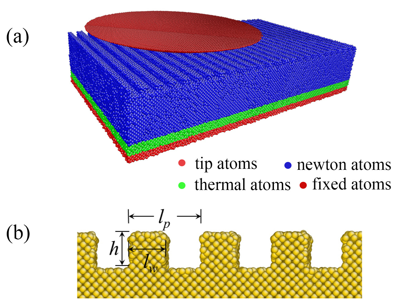
We performed MD simulations of the sliding friction of nanopatterned silicon surfaces in contact with a diamond tip, as shown in Figure 1. The nanopattern of the contact surface features a series of periodically rectangular grooves and protrusions (Figure 1a). The protrusion width lw, the protrusion height h, the nanopattern period width lp, and the area ratio λ (defined as lw/lp) determine the geometry of this nanopattern surface, as indicated in Figure 1b. In this work, we focused on the essential friction behavior of the nanopatterned surface; hence, the effects of the area ratio and the nanopattern period width were investigated. The area ratio changes in the range from 25% to 75%, and the nanopattern period widths are 2.17 nm, 4.34 nm and 6.52 nm, whereas the protrusion height of 1 nm remains constant. When constant lp and h are used, the effect of the area ratio is equivalent to the influence of the protrusion width or groove width.
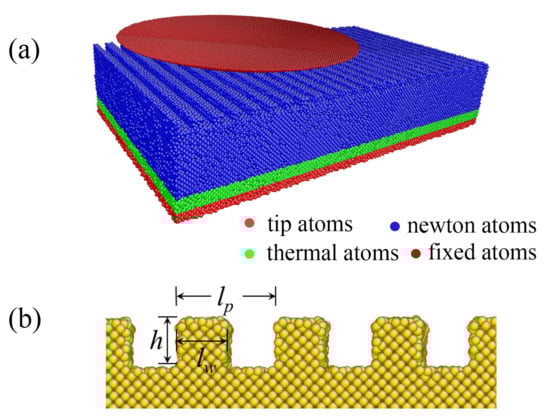
Figure 1.
The friction model for the nanopatterned silicon surface contact using a spherical diamond tip: (a) Three-dimensional view, and (b) schematic of the nanopattern.
A spherical diamond tip with a diameter of 43.45 nm is used, and it was carved out of a (100)-oriented diamond block. The tip is regarded as a rigid body due to its much greater stiffness than that of the specimen. The nanopatterned silicon specimen is fabricated from (100)-oriented single-crystal silicon and measures 54.31 × 32.59 × 10.86 nm3 along the x-, y-, and z-directions, respectively. Periodic boundary conditions are applied along both the x- and y-directions, whereas a free boundary is set along the z-direction. The Tersoff potential [23] and the Morse [24] potential are used to depict the interactions between the silicon atoms and between the carbon and silicon atoms. The parameters D, r0 and α of the Morse potential are chosen as 0.435 eV, 0.19475 nm and 4.6487 nm−1, respectively. Purely repulsive interactions are simulated by truncating the Morse potential at the minimum of the interaction force. The 1-nm-thick atom layer at the bottom of the silicon specimen is frozen to impart structural stability. A Langevin thermostat [25] is applied to a 1.63-nm-thick atom layer adjacent to the frozen layer to dissipate excessive thermal energy generated during indenting and sliding. All remaining atoms can move freely according to Newton’s equation of motion.
After the initial construction, the silicon specimen relaxes at a constant temperature of 300 K to obtain the equilibrium configuration. Subsequently, MD simulations of indentation at a constant velocity of 20 m/s along the z-direction are performed to represent normal loading. Friction is simulated by laterally sliding the tip along the x-direction (<100> crystallographic orientation) over the silicon (001) surface with a constant sliding velocity: v = 100 m/s. The process of sliding always lasts 500 ps. The friction force and normal load are averaged over time after “run-in” because of the oscillations of the friction and normal load over time. All the simulations are performed using the Verlet integration algorithm with a time step of 2.5 fs using the LAMMPS code [26].
3. Results
3.1. Friction Behavior
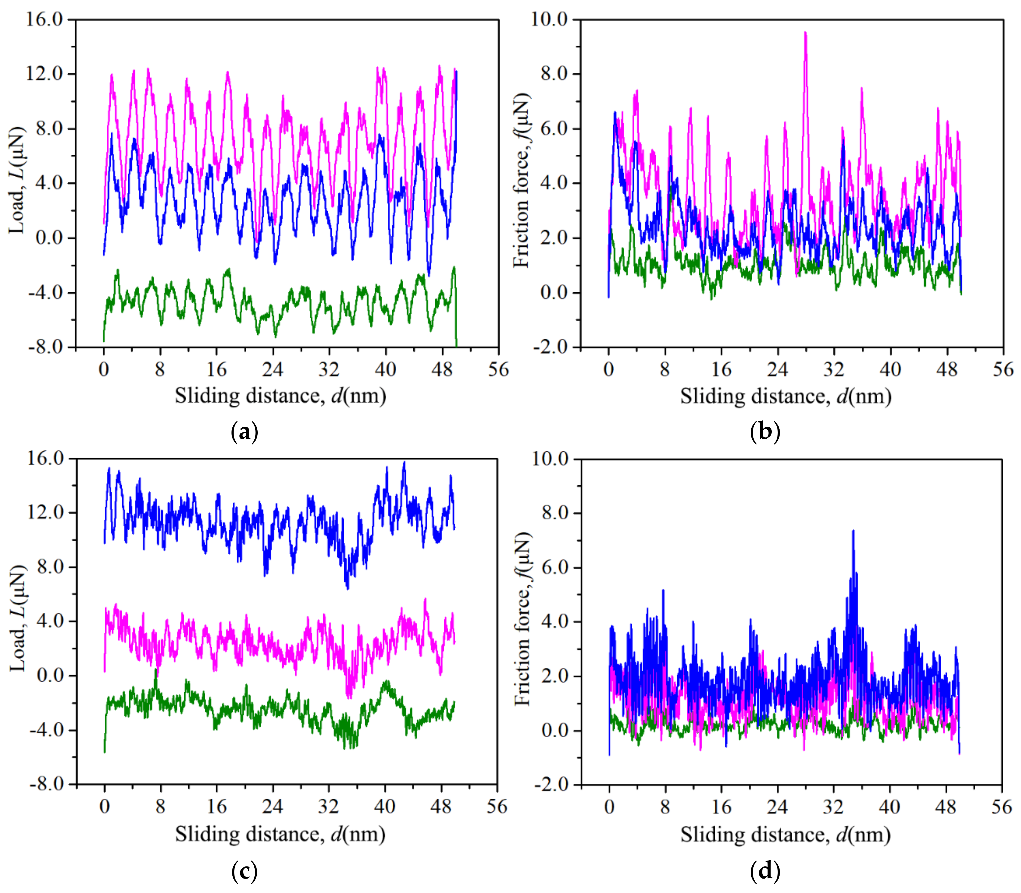
The instantaneous normal load L and instantaneous friction force f are calculated by summing all the normal and lateral interface forces of the substrate atoms acting on the tip atoms during the simulation. To eliminate the high-frequency vibration induced by the stick-slip phenomenon, the L–d and f–d curves are smoothed using adjacent-averaging method. The typical instantaneous L and f signals are displayed in Figure 2 as a foundation of the sliding distance d = v·t with v = 100 m/s. For the nanopatterned surface, the L–d and the f–d curves appear to be dominated by peaks and troughs with periodic distributions, as shown in Figure 2a,b. In contrast, the normal load and friction force fluctuate with relative small amplitude and high frequency for the smooth surface, as shown in Figure 2c,d.
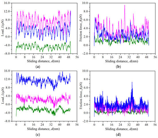
Figure 2.
Oscillation of the normal load (a,c) and the friction force (b,d) with the sliding distance for the nanopatterned surface with lp = 2.17 nm and λ = 50% (a,b) and the flat surface (c,d).
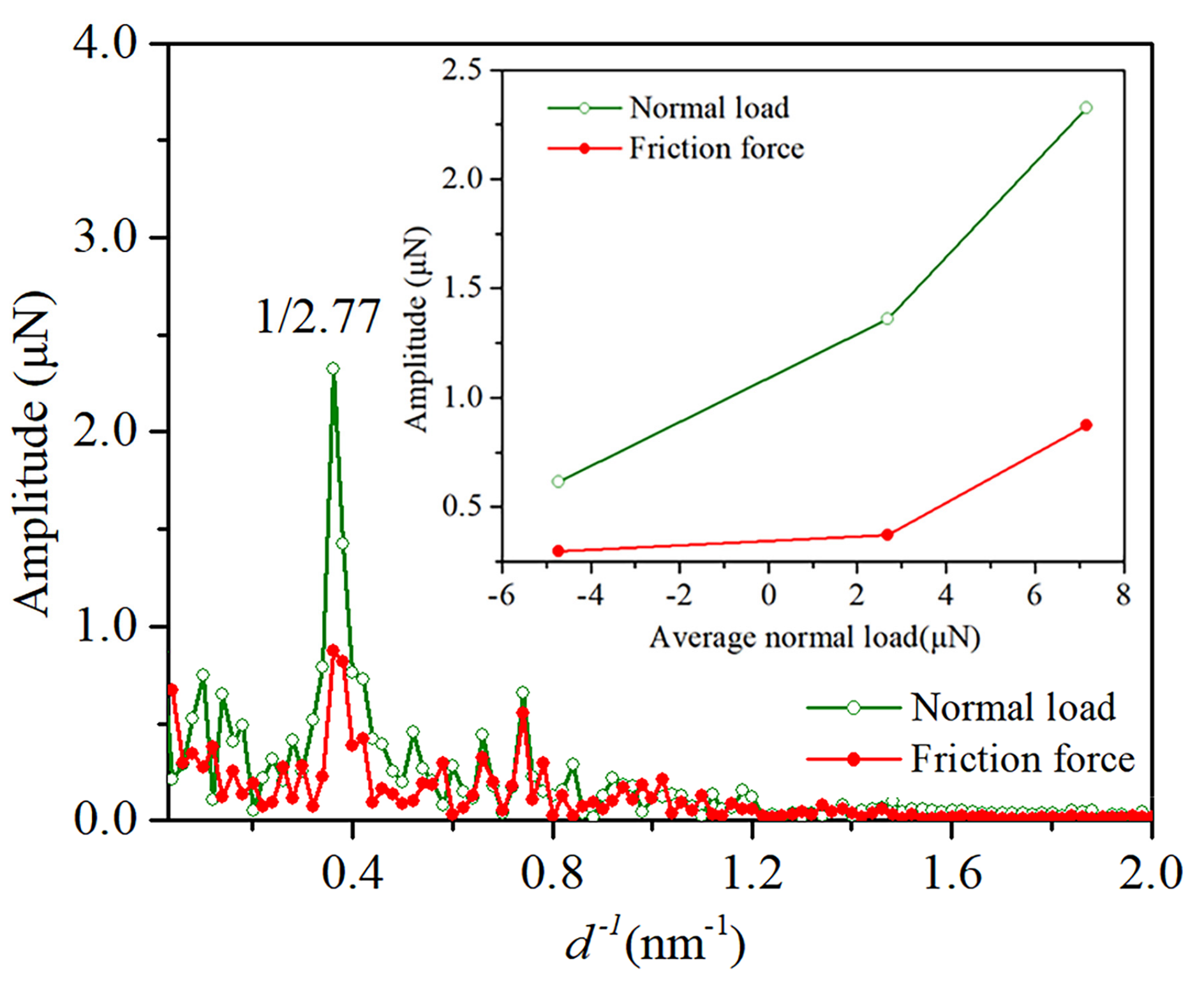
The periodic oscillations of the normal load and friction force for the nanopatterned surface were analyzed using fast Fourier transformations (FFTs), and a sample of the amplitude spectra is shown in Figure 3. The spectra of the normal load and friction force exhibit well-defined peaks at 1/2.77 nm−1, indicating a coincident periodic oscillation of the normal load and friction force with a period of 2.77 nm. The oscillation periods are slightly larger than the nanopattern period of 2.17 nm. In addition, the oscillation amplitude of the normal load increases with an increase in the average normal load, as well as the friction force, as shown in the inset in Figure 3. Moreover, the high frequency signals overlap with the periodic friction force signals, and the oscillation amplitude becomes nonuniform with a decrease in the normal load (Figure 2b), indicating inconspicuous periodic oscillations of the friction force.
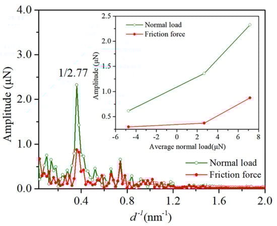
Figure 3.
Typical amplitude spectra of the L and f oscillations for the nanopatterned surface with lp = 2.17 nm and λ = 50%. The insert shows the amplitude of the normal load and friction force as a function of the average normal load.
The periodic oscillations of the normal load are easy to understand: the presence of rectangular grooves and protrusion arrays on the surface facilitates the periodic normal load when the separation between the tip and the substrate surface is held constant. The periodic oscillations of the friction force thus appear to be the product of the normal load oscillations. The synchronous oscillations of the normal load and friction force imply a linear friction law, as will be discussed later.
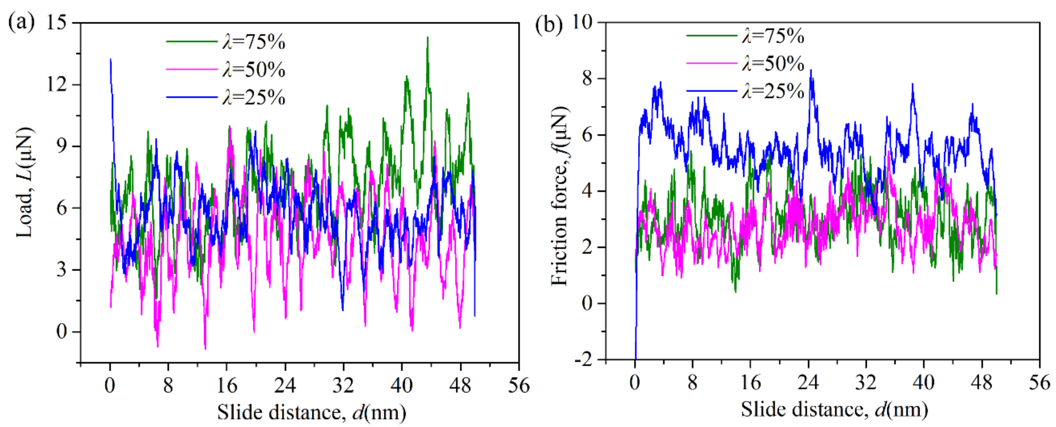
Figure 4 shows the typical L–d and the f–d curves for the three nanopatterned surfaces with lp = 2.17 nm and λ = 25%, 50% and 75%. The three nanopatterned surfaces exhibit similar periodic oscillations between the normal load and friction force with same oscillation periods of 1/2.77 nm−1 but with different oscillation amplitudes. In this figure, the average normal load of the three nanopatterned surfaces is carefully selected to be nearly equal. Notably, the nanopatterned surface with λ = 25% has a much larger average friction force than the other two nanopatterned surface; however, the friction force does not always decrease with in an increase in the area ratio.

Figure 4.
(a) Normal load, and (b) friction force as a function of the area ratio λ for nanopatterned surfaces with lp = 2.17 nm.
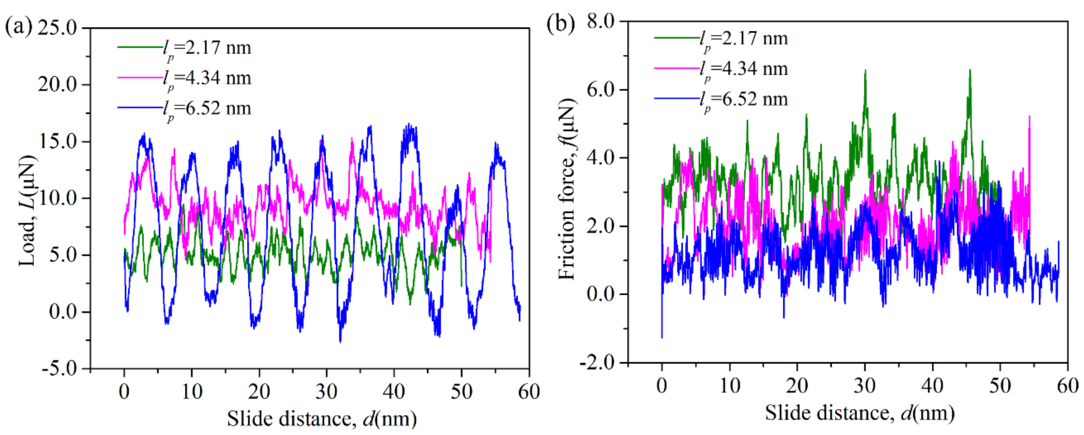
Figure 5 shows the instantaneous normal load and the friction force related to the period width lp of the nanopatterned surfaces with λ = 50%. The increase in the oscillation period and oscillation amplitude with an increase in lp is arrestive. The oscillation period increases from 1/2.77 nm−1 for the nanopatterned surface with lp = 2.17 nm to 1/4.25 nm−1 for the surface with lp = 4.34 nm to 1/6.25 nm−1 for the surface with lp = 6.52 nm, indicating the correlation between the nanopattern period and oscillation period. The large nanopattern period results indicate that the tip can barely feel the substrate when it moves into the groove, and it is rapidly captured by the substrate when it moves above the protrusions. In fact, the valleys of the normal load and friction force approximate to zero, as shown in Figure 5.
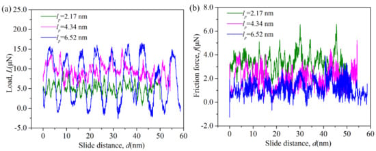
Figure 5.
(a) Normal load, and (b) friction force as a function of the period width lp for the nanopatterned surfaces with λ = 50%.
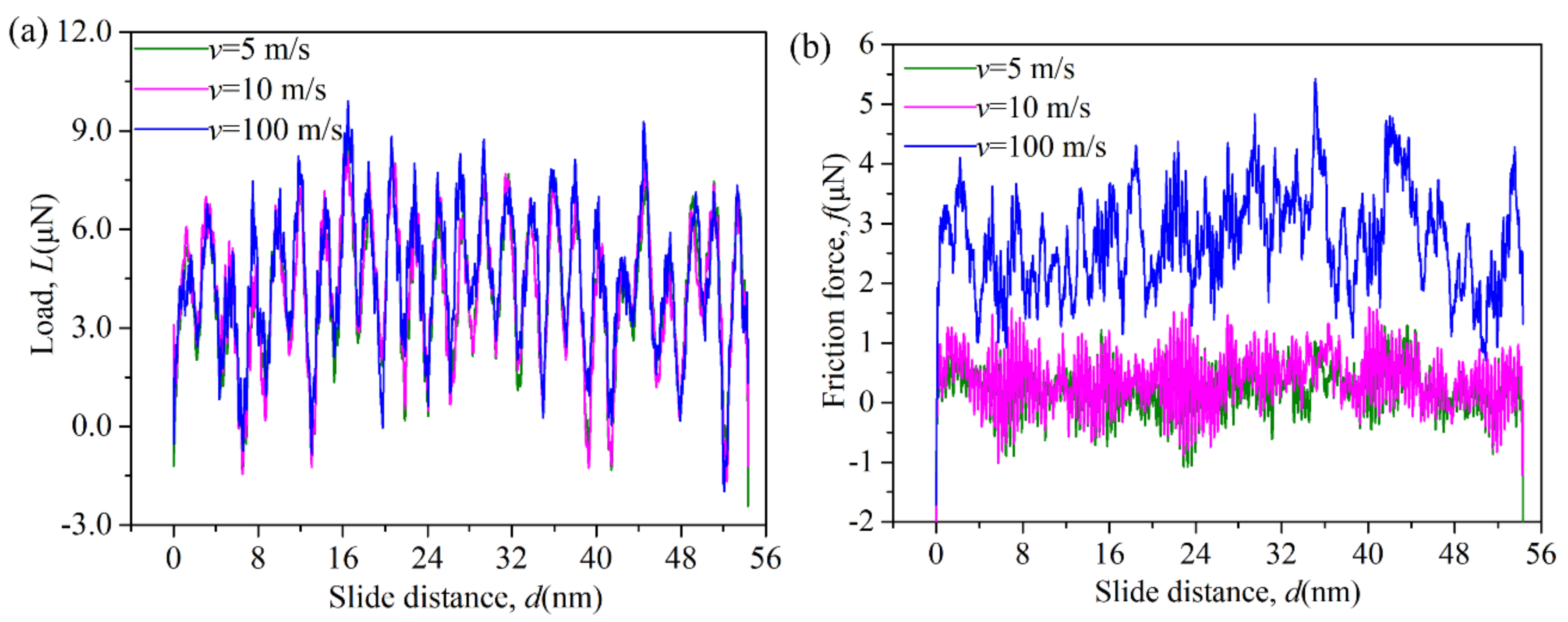
Moreover, the velocity effect on the friction behavior was also investigated. In the velocity range of 5–100 m/s, the locations of the peaks and troughs with a periodic distribution overlap for the normal load, as well as the friction force, but with different amplitudes, as shown in Figure 6. The same periodic oscillations of the normal load and friction force for the nanopatterned surface are observed for nonadhesive contact. Hence, the area ratio, the sliding velocity and the interface adhesion do not influence the oscillation period, but they affect the oscillation amplitude of the normal load and friction force, indicating the different average normal loads and friction forces.

Figure 6.
(a) Normal load and (b) friction force as a function of the sliding velocity for the nanopatterned surface with λ = 50% and lp = 2.17 nm.
At the macroscale, the micropattern-induced periodic oscillations of the normal load and friction force have been generally reported [27,28] and used to understand human tactile perception and to design tactile robotic sensing devices. Similar oscillations induced by different surface topologies have also been observed by atomic force microscopy (AFM) when a very low velocity (0.01–10 mm/s) and relatively sharp tip are used [20]. In our MD simulations, the high velocity and blunt tip relative to the pattern size are used because of computing power limitations. Our results indicate that these surface pattern-induced friction oscillations can also be found at the nanoscale, even with a very high sliding velocity and a blunt tip.
3.2. Friction Law
To discuss the friction law, the real contact area Areal is defined as the aggregate area of all atoms within contact if the atoms is within the range of 0.19475 nm interaction of any atom of the tip. Figure 7a shows the average friction force as a function of the real contact area for the nanopatterned surface with lp = 2.17 nm and λ = 50%. Notably, the friction force f is linear with the real contact area Areal both in nonadhesive contact and adhesive contact, i.e.,
where Af0 is a small offset. In nonadhesive contact, Af0 approximates to zero, i.e., f = τAreal. In adhesive contact, the disappearance of Af0 requires the normal load to become negative. The linear f–Areal relationship is also valid for the flat contact surface, as shown in Figure 8a. Our simulation data reveal that the friction force f depends linearly on the real contact area Areal for both the nanopatterned surface and the flat contact surface in either adhesive contact or in nonadhesive contact at the nanoscale. This linear real contact area dependence of the friction force has been found for H-terminated diamond surfaces [2] and atomically rough Fe surfaces [29] at the nanoscale.
f = τ(Areal − Af0)
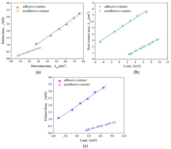
Figure 7.
(a) Friction force versus real contact area, (b) real contact area versus normal load, (c) friction force versus normal load for the nanopatterned surface with lp = 2.17 nm and λ = 50%.
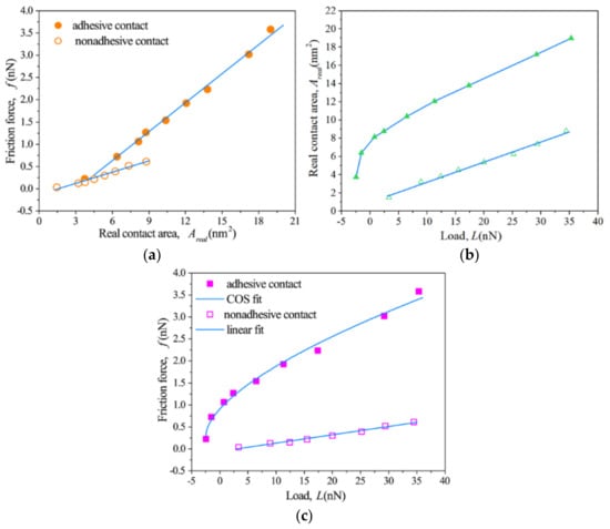
Figure 8.
(a) Friction force versus real contact area, (b) real contact area versus normal load, (c) friction force versus normal load for flat surface.
Figure 7b shows the average real contact area as a function of the normal load for the nanopatterned surface with lp = 2.17 nm and λ = 50%. The linear load dependence of the real contact area is found for the nanopatterned surface in both adhesive and nonadhesive contact, i.e.,
where a is the slope and AL0 is the real contact area at zero normal load. In nonadhesive contact, the AL0 is very small, but it becomes very large in adhesive contact. In macroscale Bowden and Tabor roughness theory, the real contact area ∑Aasp is proportional to the normal load L, i.e., ∑AaspµL, while the nominal contact area is constant. The linear dependence of f–Areal and Areal–L indicates that the roughness theories capture the nature of the friction at the nanoscale.
Areal = aL + AL0
After inspecting the linear dependence of f–Areal and Areal–L, one can immediately conclude that the friction force varies linearly with the normal load by substituting Equation (2) into Equation (1), i.e.,
where μ* is equal to τa, and L0* is equal to (Af0 − AL0)/a. Equation (3) shows the formal Amontons’ friction law, i.e., f = μ(L − L0), where μ is the friction coefficient and L0 is an offset. However, this result cannot show that Amontons’ friction law is valid at the nanoscale for the nanopatterned surface because μ* is not independent of L0*, as explained by Eder et al. [29] As shown in Figure 7c, the nanopatterned surface shows a high but finite friction force at L = 0 even at negative loads in adhesive contact, while a nearly no friction force at L = 0 is observed in nonadhesive contact. The friction force in adhesive contact is much greater than that in adhesive contact for the nanopatterned surface. Therefore, the observed linear dependence of f–L is a result of the synergistic effect between the linear dependence of f–Areal in Equation (1) and the load dependence of the real contact area in Equation (2). For the nanopatterned surface, the friction law is only the formal Amontons’ friction law, while the significant linear dependence of f–Areal and Areal–L captures the general features of nanoscale friction in both adhesive and nonadhesive single-asperity contact.
f = (τa)L + τ (AL0 − Af0) = μ*(L − L0*)
Regarding the flat contact surface, the linear dependence of f–Areal is also found for the nonadhesive contact, but the sublinear dependence of Areal–L is observed for the flat contact surface in adhesive contact, as shown in Figure 8b. We thus can conclude that the friction force f varies linearly with normal load L in nonadhesive contact, but the friction force f depends sublinearly on the normal load L in adhesive contact, as shown in Figure 8c. To quantitatively validate the continuum model in adhesive contact, we fit the simulated data to the Maugis-Dugdale model, a classical adhesive contact model, using an interpolation formula developed by Carpick, Ogletree, and Salmeron (COS) [30]. The fitted COS transition parameter is equal to 0.71, which corresponds to a Tabor parameter of 1.04. The fitted results bring the friction behavior into correspondence with the continuum model for the flat surface in adhesive contact. Our results confirm that the continuum model breaks down in nonadhesive single-asperity contact but qualitatively holds in adhesive single-asperity contact with a flat or atomically rough contact surface at the nanoscale [2,10,12,13,14]; these results agree well with the friction behavior of the H-terminated diamond surface reported by Szlufarska et al. [2].
The present results demonstrate that an increase in the adhesion force can lead to a transition from linear to nonlinear f–L dependence for a flat contact surface. In contrast, the linear f–L dependence is always observed for the nanopatterned surface in both adhesive or nonadhesive contact. Hence, two approaches, decreasing the adhesion force and introducing a nanopattern, can induce a transition from nonlinear to linear f–L dependence. Because the introduction of a nanopattern on the contact surface can change the adhesion force, one could consider that the linear f–L dependence for the nanopatterned surface in adhesive contact may be the result of the changing adhesion force. To evaluate this hypothesis, we evaluated the effect of the nanopattern on the adhesion force between the contact surfaces. The adhesion force is directly obtained from the pull-off force by simulating the trace-retrace process of the tip. The resulting adhesion forces are listed in Table 1. An adhesion reduction is observed only for the nanopatterned surface with λ = 25%. In contrast, a significant increase in adhesion is found for the nanopatterned surfaces with λ = 50% and 75%. As this article shows later, the f–L relationship for the nanopatterned surface is independent of the area ratio. Hence, the linear f–L dependence for the nanopatterned surface is attributed to the nature of the nanopattern rather than the resulting adhesion change. The incremental and decremental adhesion force for the nanopatterned surface is caused by two competitive mechanisms, the well-known contact splitting phenomenon and the decreasing real contact area, as reported previously [31].

Table 1.
Adhesive force of the nanopatterned surface with different area ratios. (An area ratio of 0 corresponds to a fat surface without nanopattern.)
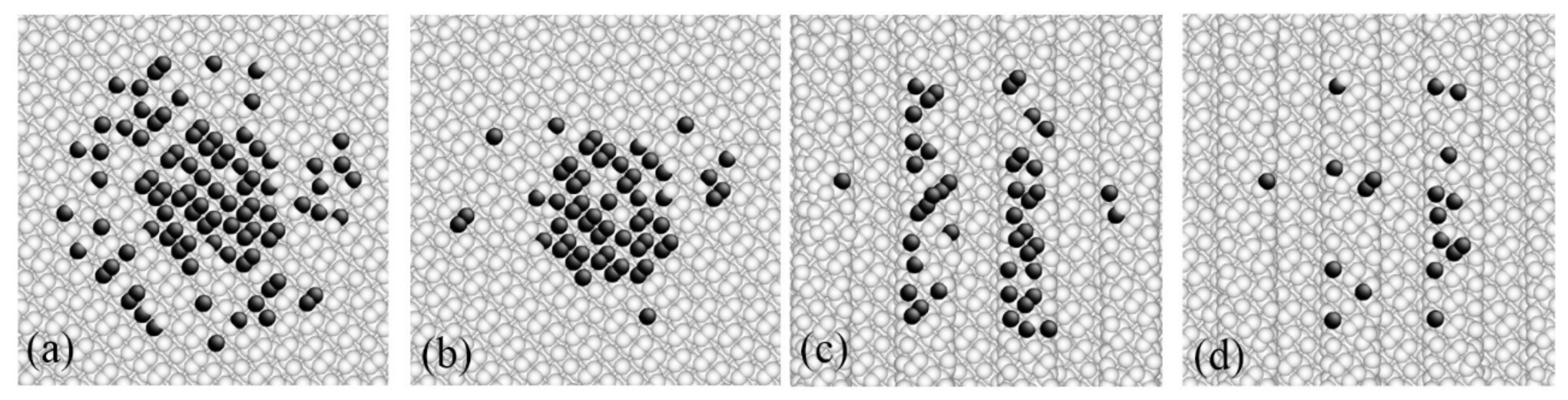
The linear dependence of f–Areal and Areal–L leads us to conclude that the friction law of the nanopatterned surface in single-asperity contact correlates with the macroscale Bowden and Tabor roughness theory. Roughness theories predict that the normal load depends linearly on the real contact area of all contacting asperities, i.e., f = τ∑Aasp, rather than the nominal contact area. To investigate the roughness of the nanopatterned surface in single-asperity contact, the maps of the real contact area are calculated and shown in Figure 9. The real contact area is comprised of numerous discrete atoms. The contact atoms become increasingly sparse away from the contact center. For the nanopatterned surface, the real contact surface is divided into several discrete atom islands by the nanopattern, as indicated in Figure 9c,d. Thus, the real contact area is far less than the nominal contact area, which is defined as the convex hull that encloses all contact atoms, both for the flat surface and nanopatterned surface. This result highlights the atom-scale rough nature of dry contact. The configuration of real contact atoms can be modulated by the nanopattern and results in an ordered corrugation of surface potential energy for the nanopatterned surface. This additional ordered corrugation of surface potential energy enhances the friction of the nanopatterned surface, even though the nanopatterned surface has fewer contact atoms than the flat surface, as shown in Figure 9.
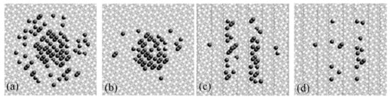
Figure 9.
The real contact area of (a) the flat surface in adhesive contact, (b) the flat surface in nonadhesive contact, (c) the nanopatterned surface with lp = 2.17 nm and λ = 50% in adhesive contact, and (d) the same surface in nonadhesive contact.
In adhesive contact, the model of the classical continuum adhesive contact can accurately predict the nanoscale friction behavior of the flat contact surface, as previously mentioned, but this model becomes invalid for the nanopatterned surface. Introducing the nanopattern on the contact surfaces affects the friction in at least two ways. On the one hand, the nanopattern can modulate the adhesive force between the contact surfaces, thus influencing the friction force. This effect on friction is relatively complex because the adhesive force may be enhanced or may be weakened depending the geometrical parameters of the nanopattern. On the other hand, the nanopattern forms an additional geometrical interlock, which enhances the friction force. This interlock effect can be described by Euler’s interlocking asperity model, devised in the 18th century, which predicts a linear f–L dependence in which the friction coefficient is equal to the local slope. Therefore, the friction force of the nanopatterned surface in adhesive contact can be phenomenologically expressed as:
where fflat describes the friction force of the flat contact surface, fadh represents the additional contribution of the adhesion change originating from the nanopattern, and fgeo is the contribution of the geometrical interlock. If a nanopattern does not exist, then the friction force fflat is a sublinear function of the normal load in adhesive contact. In addition, fgeo has a linear dependence on the normal load. Thus, the relationship depends on the relative intensity of fflat, fadh and fgeo. If the geometrical interlock effect dominates the friction behavior or if the nanopattern strongly suppresses the adhesion reduction, then the nanopatterned surface will show a linear load dependence on the friction force; otherwise, the sublinear f–L relationship will hold.
f = fflat + fadh + fgeo
3.3. Geometry Effect on the Friction
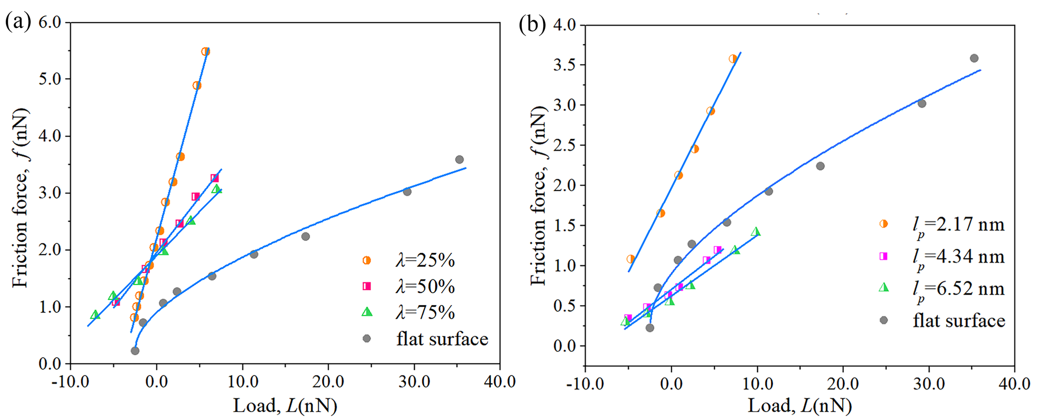
The geometry effect of the nanopatterned surface on the friction law was further investigated. Figure 10a shows the f–L dependence as a function of the area ratio λ with a constant nanopattern period lp of 50%. The linear dependences of f–L are maintained when the area ratio of the nanopatterned surface changes within the range of 25% to 75%. Both the fitted slope μ* and offset L0* monotonically decrease with an increase in the area ratio, and thus the three f–L curves only intersect at one point, as indicated in Figure 9a. Hence, for a large normal load, the friction force decreases with an increase in the area ratio, but the opposite occurs for a small normal load. This result reveals that although the linear load dependence of the friction force is independent of the geometry parameters, the fitted slope μ* and offset L0* vary significantly with the geometry parameters of the nanopatterned surface. Moreover, the nanopatterned surfaces with lp = 50% exhibit greater friction forces than the flat surface at any load.
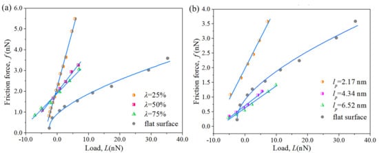
Figure 10.
The effect of the area ratio (a), and nanopattern period (b) on the f–L dependence of the nanopatterned surface in adhesive contact.
Figure 10b shows the f–L dependence as a function of the nanopattern period lp with a constant area ratio λ of 50%. The linear load dependence of the friction force is valid for all cases. Both the fitted slope μ* and offset L0* monotonically decrease with an increase in the nanopattern period. However, the decrease in the fitted slope μ* and offset L0* is very small when the nanopattern period increases from 4.34 nm to 6.52 nm. Interestingly, the desired friction reduction can be obtained when the nanopattern period lp is larger than 4.34 nm, but significant friction enlargement is observed for the nanopattern with a small lp of 2.17 nm.
Our simulation data indicates that the linear load dependence of the friction force always holds in the lp range of 2.17 nm to 6.52 nm and λ range of 25% to 75%. The nanopattern can not only enlarge the friction force but can also significantly reduce the friction force. The enlargement and reduction of the friction force critically depends on the nanopattern period rather than the area ratio. The large nanopattern period facilitates the friction reduction.
4. Conclusions
A series of MD simulations were performed to investigate the friction of nanopatterned surfaces with periodical rectangular groove arrays in dry and wear-less single-asperity contact. The evolution of the normal load and friction force signal, friction law, and nanopattern geometry and adhesion effect on the friction behavior were discussed in detail. The synchronous and periodic oscillations of the normal load and friction force with the sliding distance were determined at frequencies defined by the nanopattern period in both adhesive and nonadhesive contact. The geometry of the nanopattern has a significant effect on the spectral content of the normal load and friction force.
The linear load dependence of the friction force always holds for the nanopatterned surface in both adhesive and nonadhesive single-asperity contact and is independent of the nanopattern geometry. We show that the linear friction law is a formal Amontons’ friction law, while the significant linear dependence of f–Areal and Areal–L captures the general features of nanoscale friction in both adhesive and nonadhesive single-asperity contact. In contrast, a transition from the linear to nonlinear load dependence of the friction force for a flat contact surface was observed when adhesion force was introduced on the contact surface. We thus conclude that two approaches, decreasing the adhesion force and introducing a nanopattern, can induce a nonlinear-to-linear f–L dependence transition at the nanoscale for single-asperity contact.
Moreover, the nanopattern can not only enlarge the friction force but also significantly reduce the friction force, and this control is urgently needed at the nanoscale. The enlargement and reduction of the friction critically depended on the nanopattern period rather than the area ratio. The large nanopattern period facilitated the friction reduction and vice versa. For a large normal load, the friction force decreases with an increase in the area ratio, but the opposite occurs for a small normal load. Our simulation results revealed that the nanopattern can modulate the friction behavior at the nanoscale from the friction signal to the friction law and to the value of the friction force. Thus, elaborate nanopatterning is an effective strategy to tune both friction and adhesion at the nanoscale.
Acknowledgments
The authors acknowledge financial support received from the National Natural Science Foundation of China (Grant No. 51505479 and 51605139), the Natural Science Foundation of Jiangsu Province (Grant No. BK20150184 and BK20160867), the Fundamental Research Funds for the Central Universities (Grant No. 2015XKMS019), China Postdoctoral Science Foundation (Grant No. 2014M551686). We also acknowledge the support of A Project Funded by the Priority Academic Program Development of Jiangsu Higher Education Institutions.
Author Contributions
Jing Han, Hua Zhu and Liang Fang designed the project and guided the research. Jing Han, Jiapeng Sun prepared the manuscript. Song Xu performed a part of simulations; Ying Han, Dan Song and Jiapeng Sun analyzed the data. All authors reviewed the manuscript and contributed to the discussions.
Conflicts of Interest
The authors declare no conflict of interest.
References
- Amontons, G. De la resistance cause´e dans les machines. Mem. Acad. R. Sci. A 1699, 44, 257–282. [Google Scholar]
- Mo, Y.F.; Turner, K.T.; Szlufarska, I. Friction laws at the nanoscale. Nature 2009, 457, 1116–1119. [Google Scholar] [CrossRef] [PubMed]
- Burton, Z.; Bhushan, B. Hydrophobicity, adhesion, and friction properties of nanopatterned polymers and scale dependence for micro- and nanoelectromechanical systems. Nano Lett. 2005, 5, 1607–1613. [Google Scholar] [CrossRef] [PubMed]
- Zou, M.; Cai, L.; Wang, H. Adhesion and friction studies of a nano-textured surface produced by spin coating of colloidal silica nanoparticle solution. Tribol. Lett. 2006, 21, 25–30. [Google Scholar] [CrossRef]
- Zhang, X.; Wu, C.; Che, H.; Hou, J.; Jia, J. Friction behavior of nano-textured polyimide surfaces measured by AFM colloidal probe. Appl. Surf. Sci. 2014, 320, 328–333. [Google Scholar] [CrossRef]
- Zhao, W.; Wang, L.; Xue, Q. Design and fabrication of nanopillar patterned au textures for improving nanotribological performance. ACS Appl. Mater. Interfaces 2010, 2, 788–794. [Google Scholar] [CrossRef] [PubMed]
- Song, H.; Ji, L.; Li, H.; Liu, X.; Zhou, H.; Liu, L.; Chen, J. Superlow friction behavior of surface-textured a-C:H film in water environments. Tribol. Trans. 2015, 58, 867–874. [Google Scholar] [CrossRef]
- Li, J.; Xiong, D.; Wu, H.; Huang, Z.; Dai, J.; Tyagi, R. Tribological properties of laser surface texturing and molybdenizing duplex-treated Ni-base alloy. Tribol. Trans. 2010, 53, 195–202. [Google Scholar] [CrossRef]
- Zou, M.; Cai, L.; Yang, D.H. Nanotribology of a silica nanoparticle-textured surface. Tribol. Trans. 2006, 49, 66–71. [Google Scholar] [CrossRef]
- Mo, Y.F.; Szlufarska, I. Roughness picture of friction in dry nanoscale contacts. Phys. Rev. B 2010, 81, 035405. [Google Scholar] [CrossRef]
- Gao, J.P.; Luedtke, W.D.; Gourdon, D.; Ruths, M.; Israelachvili, J.N.; Landman, U. Frictional forces and Amontons’ law: From the molecular to the macroscopic scale. J. Phys. Chem. B 2004, 108, 3410–3425. [Google Scholar] [CrossRef]
- Luan, B.Q.; Robbins, M.O. Contact of single asperities with varying adhesion: Comparing continuum mechanics to atomistic simulations. Phys. Rev. E 2006, 74, 026111. [Google Scholar] [CrossRef] [PubMed]
- Cheng, S.F.; Luan, B.Q.; Robbins, M.O. Contact and friction of nanoasperities: Effects of adsorbed monolayers. Phys. Rev. E 2010, 81, 016102. [Google Scholar] [CrossRef] [PubMed]
- Luan, B.Q.; Robbins, M.O. The breakdown of continuum models for mechanical contacts. Nature 2005, 435, 929–932. [Google Scholar] [CrossRef] [PubMed]
- Gao, G.T.; Cannara, R.J.; Carpick, R.W.; Harrison, J.A. Atomic-scale friction on diamond: A comparison of different sliding directions on (001) and (111) surfaces using MD and AFM. Langmuir 2007, 23, 5394–5405. [Google Scholar] [CrossRef] [PubMed]
- Carpick, R.W.; Salmeron, M. Scratching the surface: Fundamental investigations of tribology with atomic force microscopy. Chem. Rev. 1997, 97, 1163–1194. [Google Scholar] [CrossRef] [PubMed]
- Marchetto, D.; Rota, A.; Calabri, L.; Gazzadi, G.C.; Menozzi, C.; Valeri, S. AFM investigation of tribological properties of nano-patterned silicon surface. Wear 2008, 265, 577–582. [Google Scholar] [CrossRef]
- Marchetto, D.; Rota, A.; Calabri, L.; Gazzadi, G.C.; Menozzi, C.; Valeri, S. Hydrophobic effect of surface patterning on Si surface. Wear 2010, 268, 488–492. [Google Scholar] [CrossRef]
- Choi, D.; Kim, S.; Lee, S.; Kim, D.; Lee, K.; Park, H.; Hwang, W. Structure-dependent adhesion and friction on highly ordered metallic nanopore membranes. Nanotechnology 2008, 19, 145708. [Google Scholar] [CrossRef] [PubMed]
- Pilkington, G.A.; Thormann, E.; Claesson, P.M.; Fuge, G.M.; Fox, O.J.L.; Ashfold, M.N.R.; Leese, H.; Mattia, D.; Briscoe, W.H. Amontonian frictional behaviour of nanostructured surfaces. Phys. Chem. Chem. Phys. 2011, 13, 9318–9326. [Google Scholar] [CrossRef] [PubMed]
- Zhang, X.L.; Lu, Y.J.; Liu, E.Y.; Yi, G.W.; Jia, J.H. Adhesion and friction studies of microsphere-patterned surfaces in contact with atomic force microscopy colloidal probe. Colloid Surf. A 2012, 401, 90–96. [Google Scholar] [CrossRef]
- Zou, M.; Wang, H.Y.; Larson, P.R.; Hobbs, K.L.; Johnson, M.B.; Awitor, O.K. Ni nanodot-patterned surfaces for adhesion and friction reduction. Tribol. Lett. 2006, 24, 137–142. [Google Scholar] [CrossRef]
- Tersoff, J. Empirical interatomic potential for silicon with improved elastic properties. Phys. Rev. B 1988, 38, 9902–9905. [Google Scholar] [CrossRef]
- Cheong, W.; Zhang, L.C. Molecular dynamics simulation of phase transformations in silicon monocrystals due to nano-indentation. Nanotechnology 2000, 11, 173–180. [Google Scholar] [CrossRef]
- Schneider, T.; Stoll, E. Molecular-dynamics study of a three-dimensional one-component model for distortive phase transitions. Phys. Rev. B 1978, 17, 1302–1322. [Google Scholar] [CrossRef]
- Plimpton, S. Fast parallel algorithms for short-range molecular dynamics. J. Comput. Phys. 1995, 117, 1–19. [Google Scholar] [CrossRef]
- Scheibert, J.; Leurent, S.; Prevost, A.; Debregeas, G. The role of fingerprints in the coding of tactile information probed with a biomimetic sensor. Science 2009, 323, 1503–1506. [Google Scholar] [CrossRef] [PubMed]
- Wandersman, E.; Candelier, R.; Debrégeas, G.; Prevost, A. Texture-induced modulations of friction force: the fingerprint effect. Phys. Rev. Lett. 2011, 107, 164301. [Google Scholar] [CrossRef] [PubMed]
- Eder, S.J.; Feldbauer, G.; Bianchi, D.; Cihak-Bayr, U.; Betz, G.; Vernes, A. Applicability of macroscopic wear and friction laws on the atomic length scale. Phys. Rev. Lett. 2015, 115, 025502. [Google Scholar] [CrossRef] [PubMed]
- Carpick, R.W.; Ogletree, D.F.; Salmeron, M. A general equation for fitting contact area and friction vs. load measurements. J. Colloid Interface Sci. 1999, 211, 395–400. [Google Scholar] [CrossRef] [PubMed]
- Varenberg, M.; Murarash, B.; Kligerman, Y.; Gorb, S.N. Geometry-controlled adhesion: Revisiting the contact splitting hypothesis. Appl. Phys. A Mater. 2011, 103, 933–938. [Google Scholar] [CrossRef]


© 2017 by the authors. Licensee MDPI, Basel, Switzerland. This article is an open access article distributed under the terms and conditions of the Creative Commons Attribution (CC BY) license (http://creativecommons.org/licenses/by/4.0/).