Abstract
High-voltage direct current gas-insulated equipment (HVDC GIE) is becoming a key component in DC transmission systems due to its compactness and reliability, particularly for cost-effective offshore wind power integration. However, its reliability is compromised by surface charge accumulation at the gas–solid interface—a problem intensified by metallic contaminants and the adoption of eco-friendly gas mixtures. Addressing this challenge requires not only material and design innovations but also the development of standardized testing protocols to validate insulation performance. This review systematically examines the critical, interconnected areas essential for advancing HVDC GIE, focusing on the dynamics of charged metallic particles and their role in charge accumulation, interface charge behavior under alternative gas environments, and experimental methodologies with evolving test standards. By synthesizing insights across these domains, this work aims to provide both theoretical insights and practical guidance for optimizing HVDC GIE insulation design formulating scientifically grounded operation and maintenance strategies.
1. Introduction
With the rapid growth of global energy consumption, climate change and ecological environmental protection have emerged as critical issues of worldwide concern, underscoring the increasing importance of utilizing clean and renewable energy sources. Among these, offshore wind farms have attracted extensive global attention due to their vast untapped wind resources and superior wind conditions [1,2]. Currently, the development of offshore wind power is progressively advancing into far-sea areas, where large-capacity, long-distance power collection and transmission technologies, along with related equipment, have become pivotal for the large-scale exploitation and utilization of wind energy in deep-sea regions [1,2,3,4].
For offshore wind power transmission, three primary technologies are employed: high-voltage alternating current (HVAC), low-frequency alternating current (LFAC), and high-voltage direct current (HVDC) [5]. HVDC is often the preferred solution due to its distinct advantages in cost, efficiency, and applicability, particularly when the transmission distance exceeds 80 km and the capacity surpasses 500 MW [6]. As a core component in constructing offshore converter stations, high-voltage direct current gas-insulated equipment (HVDC GIE) enables a significant reduction in the dimensions of internal insulation structures [7], thereby minimizing the overall platform volume by over 10%.
Under DC operating voltage, basin-type insulators—which serve as conductor supports—are prone to unique surface charge accumulation that can lead to insulation failure. Compounding this issue, the inevitable presence of metallic particles within the equipment can also trigger insulation flashover faults. This occurs as particles migrate to the insulator surface, distorting the electric field distribution, particularly at the electrode-insulator interface, where significant particle accumulation tends to occur [8]. At present, effective methods for controlling metallic particles inside GIE remain lacking.
Beyond internal insulation challenges, practical long-term operational experience with DC GIE remains limited compared to AC systems. Complete testing protocols and standards—especially those involving long-term energized tests under realistic operating conditions—are still under development, with relevant research guidelines actively being discussed [9,10].
Adding to these difficulties, and in alignment with China’s “Dual Carbon” goals, the strong greenhouse effect of SF6 has motivated widespread research into eco-friendly insulating gas equipment. Should such gases be introduced into HVDC GIE for offshore wind power applications, key performance aspects including partial discharge characteristics, breakdown behavior, gas–solid surface discharge, and interface charge accumulation under high DC voltage must be thoroughly evaluated—posing yet another considerable challenge [11,12].
Therefore, in addition to the unique issue of gas–solid interface charge accumulation addressed in Part I, this study systematically reviews and synthesizes domestic and international research on several emerging challenges—including metallic particles and their mitigation, testing protocols and standards for GIE, and the evolution of accumulation-dissipation characteristics under eco-friendly insulating gas atmospheres—from the following three perspectives:
- Hazards of metallic contaminants and their mitigation methods;
- Influence of eco-friendly insulating gas environments on accumulation characteristics at gas–solid interfaces;
- Experimental methodologies for HVDC GIE.
By analyzing the current state of global research, this paper identifies limitations in existing studies, suggests future research directions, and offers recommendations for the development of this field.
2. Hazards and Mitigation of Metallic Particles
The adhesion of metallic particles to the insulator surface or the electrode-insulator interface significantly distorts the original electric field distribution at the gas–solid interface and reduces the surface flashover voltage. Developing effective mitigation methods for these particles is therefore a critical aspect of HVDC GIE insulation design. A fundamental understanding of metallic particle motion is a prerequisite for proposing such effective mitigation strategies. The following section first briefly introduces research progress on the motion behavior of metallic particles under DC voltage, and then reviews existing particle mitigation methods.
2.1. Metallic Charged Particles and Their Hazards to Gas–Solid Insulation
Research on the motion characteristics of metallic particles in HVDC GIE has been primarily conducted through experimental, simulation, or combined approaches [13,14,15]. For experimental observation and measurement, high-speed cameras, ultra-high frequency (UHF) sensors, and ultrasonic sensors play important roles. Among these, the high-frame-rate capability of high-speed cameras enables continuous capture of particle trajectories, making it an effective means for investigating particle motion behavior. Simulation analyses of particle motion are commonly performed using software such as COMSOL Multiphysics 6.2 and ANSYS 2023 R2. By establishing motion models for charged particles and inputting relevant physical parameters—such as electric field strength, gas pressure, particle radius, and initial position—researchers can simulate and analyze the lift-off voltage, motion trajectory, and final resting or adhesion positions of metallic particles [16,17]. However, accurately describing and interpreting the motion characteristics of charged metallic particles requires a clear understanding of their charging and force mechanisms.
2.1.1. Force Analysis on Metallic Charged Particles
The charging of metallic particles primarily occurs through three mechanisms: (i) conduction charging via conductors or coated dielectric surfaces, (ii) micro-discharges between particles and electrodes, and (iii) corona discharge at particle tips [18]. Once charged, the particles are predominantly subjected to Coulomb force (Fq), gravitational force (G), electric field gradient force (Fg), and gas drag force (Fv) [18,19,20,21,22]. The direction and mathematical expressions of these forces are summarized in Table 1.
The Coulomb force (Fq) represents the force acting on a charged metallic particle in an electric field, where Fq− represents Coulomb force for particle with negative charge, Fq+ represents Coulomb force for particle with positive charge. Gravitational force (G) describes the attraction due to Earth’s gravity. The electric field gradient force (Fg) characterizes the net force on the dipole moment of a metallic particle in a non-uniform electric field, which acts regardless of whether the particle is charged. The gas drag force (Fv) reflects the influence of gas dynamic parameters on particle motion [23].

Table 1.
Dominant Forces on Metallic Particles in HVDC GIE. Summarized from reference [24].
Table 1.
Dominant Forces on Metallic Particles in HVDC GIE. Summarized from reference [24].
| Force Type | Force Direction | Force Magnitude Expression |
|---|---|---|
| Coulomb Force | −r (q < 0) | |
| +r (q > 0) | ||
| Gravitational Force | −z | |
| Electric Field Gradient Force | r | |
| Gas Drag Force | −v |
In the mathematical expressions presented in Table 1, k denotes the image charge correction factor, where k = 0.832 when the particle is in contact with the electrode and k = 1 otherwise [24]; a is the particle radius; ρ is the particle density; g is the acceleration due to gravity; q is the particle charge; and E is the electric field strength between the electrodes. ε0 represents vacuum permittivity, εr represents relative permittivity, r represents the distance from the particle to the axis of the HV conductor, Udc represents the DC voltage amplitude, R1 represents the outer radius of HV conductor, R2 represents the inner radius of the grounded enclosure, Re represents the Reynolds number, ρgas represents the density of insulating gas, v represents relative velocity of particles and gas.
We have developed a simulation model for the motion of metallic particles in electric fields. By introducing correction factors such as the electric field force correction coefficient (λe) and the wall effect correction coefficient (λw), they investigated the process and principles governing the collision of charged metallic particles with electrodes [25].
2.1.2. Motion Characteristics of Metallic Charged Particles
The motion behavior of metallic particles poses significant risks to the insulation performance of GIE and is influenced by multiple factors, among which electric field distribution, voltage polarity, gas pressure, particle shape, and particle size are particularly critical. To simulate the axially non-uniform electric field in GIE, wedge-shaped, plate, or coaxial cylindrical electrodes are widely adopted in accordance with the electric field distribution characteristics within the enclosure.
In our simulation model, a stochastic restitution coefficient and random reflection angle were introduced to investigate the motion characteristics of metallic particles of different sizes and materials. The results indicate that particles undergo oscillatory motion between the electrodes, as illustrated in Figure 1, with higher oscillation frequencies corresponding to greater particle velocities. As the particle radius and material density increase, the intensity of particle motion diminishes—manifested as reduced collision frequency with electrodes and lower velocities—and the range of motion within the radial plane also decreases [25].
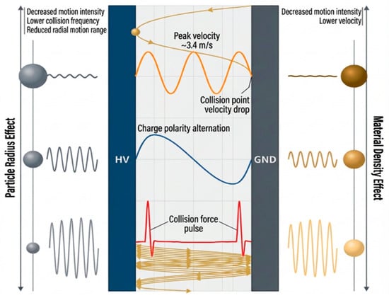
Figure 1.
Harmonic motion characteristics of metallic particles in GIS and parameter influence mechanisms. Adapted from reference [25].
Jia et al. utilized a simplified wedge-shaped electrode setup to simulate the non-uniform field distribution in actual enclosures. Their findings indicate that conductive particles exhibit oscillatory motion under DC fields. When the angle between the insulator and the grounded electrode is acute, the lift-off voltage for particles initially close to the insulator decreases substantially [26,27]. However, the wedge-shaped electrode model cannot fully replicate the electric field distribution within real enclosures.
To address this limitation, Wang et al. developed a simulation model of metallic particle motion in a coaxial cylindrical electrode configuration. Their study demonstrates that the oscillation frequency of metallic particles in the gas gap is inversely proportional to the particle radius, SF6 concentration, and gas pressure, while the intensity of motion is positively correlated with the voltage amplitude and the collision reflection angle [27,28]. Additionally, gas pressure [29], particle shape and size [30] also exert a non-negligible influence on the motion characteristics of metallic particles.
Cheng et al., through combined experimental and simulation studies, investigated the lift-off and motion behavior of wire-shaped particles. Upon reaching the lift-off voltage under positive polarity, one end of a wire-shaped particle rises, leading to small-amplitude bouncing, rotation, or vertical standing on the lower plate, with full gap crossing being difficult. Shorter particles tend to enter a bouncing state more readily after initiation, while longer ones are more likely to remain upright. Under negative polarity, however, wire-shaped particles cross the gap and frequently exhibit the “firefly motion”—a phenomenon where particles hover and bounce near the negative electrode, accompanied by corona discharge [31]. Chang et al. experimentally captured this firefly motion of wire-shaped particles, as shown in Figure 2. The high-voltage conductor is the core structure of current-carrying of GIS, primarily serving to transmit high-voltage energy and typically made of oxygen-free copper or copper alloy materials. The grounding shell serves as the enclosed protection and grounding barrier for GIS, generally constructed from aluminum alloy castings or low-carbon steel weldments. The high-voltage conductor and the grounding shell are coaxially arranged, with the conductor located at the center of the shell, and the annular gap between them filled with insulating gas. Their work revealed that space charge near the particle causes a reversal in the polarity of its charge, identifying the corona inception voltage as the critical point for this polarity reversal [32,33].
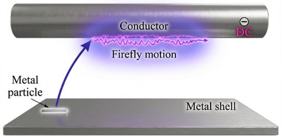
Figure 2.
Firefly motion. Adapted from references [32,33].
2.1.3. Charged Particle-Induced Charge Accumulation at the Gas–Solid Interface
In recent years, concerns over surface charge accumulation on insulators and metallic particle contamination in GIE have grown significantly, prompting extensive research into the mechanisms of charge accumulation on insulators and the impact of metallic particles on insulation performance [34]. Hiroyuki et al. numerically investigated the influence of metallic particles on surface charge accumulation by varying material volume and surface conductivity in simulations, with experimental validation [35]. Their findings indicate that metallic particles can induce radial charge accumulation on the insulator surface. Once charge attaches to the insulator surface, it becomes more prone to migrate across the surface.
Zhang et al. discovered that metallic particles can alter surface charge accumulation patterns, with their adhesion often leading to the formation of localized surface charge patches [36]. Through combined experimental and 3D simulation studies, Li et al. demonstrated that metallic particles significantly enhance charge accumulation on the insulator surface and distort the electric field distribution. Their work also indicated that increasing the SF6 pressure within the equipment helps mitigate this effect [37].
Gao et al. measured the surface charge accumulation characteristics of a 100-kV GIE epoxy insulator. Under negative DC voltage, positive charges were found to concentrate in non-planar regions of elliptical speckles, with the highest charge density near the high-voltage electrode. The coverage area expanded with increasing voltage, as illustrated in Figure 3. The radial bimodal distribution was formed by the competition among three conduction paths, with gas conduction dominating the charge accumulation process. They concluded that on insulators with complex surface topography, charge accumulation behavior is primarily governed by gas conduction, and that grounded metallic particles significantly promote local charge accumulation by distorting the electric field [38,39].
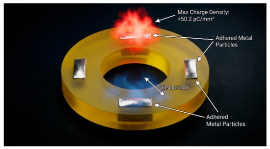
Figure 3.
Surface Charge Distribution on an Insulator with Adhered Metallic Particles. Adapted from references [38,39].
However, most existing studies have focused on surface charge accumulation after metallic particles have adhered to the insulator, with limited research addressing the influence of moving metallic particles on surface charge. He et al. investigated this using different types of moving metallic particles and found that they enhance heteropolar charge accumulation on the insulator surface. Specifically, needle-shaped particles increase charge accumulation in the form of concentrically distributed bipolar surface charges, while spherical particles contribute through point-injected charge accumulation [40].
In summary, experimental studies have consistently shown that charged particles invariably exacerbate surface charge accumulation on insulators, leading to a distorted electric field distribution along the surface. Based on the established understanding that electric field distortion is a key precursor to surface discharge, extensive studies confirm that the adhesion of metallic particles significantly reduces the surface flashover voltage, thereby degrading insulation performance. Consequently, the mitigation of metallic particles within GIE equipment remains a critical research direction.
2.2. Metallic Particle Mitigation Methods
Current techniques for suppressing and mitigating metallic particles in GIE primarily include electrode surface coating, particle traps, repelling electrodes, and synergistic application of multiple methods [41]. Electrode surface coating significantly improves surface roughness, reduces defects, and enhances insulation strength. Its mechanism for particle suppression is manifested in three aspects:
- (i)
- The high resistivity of the resistive coating effectively restricts the development of pre-discharge in gas gaps, thereby increasing the gas breakdown voltage [42];
- (ii)
- Coating the metallic electrode surface raises the lift-off electric field strength of particles [43];
- (iii)
- The coating reduces the charge transferred to particles via micro-discharges during collisions with the electrode, consequently decreasing particle charge and suppressing particle mobility [44].
Sakai et al. measured the charge on particles over coated electrodes, showing that under DC voltage, the charge acquired by particles is 45%–80% of that on uncoated electrodes [45]. Ni et al. investigated the influence of electrode coating on metallic particle charge and motion suppression under different DC voltage polarities. They proposed an activity index to characterize the motion intensity of metallic particles and analyzed this index under various coating schemes [46].
The use of particle traps is considered another effective approach for metallic particle mitigation, particularly in HVDC GIE, where particles exhibit high velocity and momentum. By incorporating dedicated trap structures on the ground electrode, particle escape can be blocked, and their velocity effectively reduced [47]. Particle traps can be designed in various shapes [48], and their effectiveness primarily depends on the slot width, density, depth, as well as the trajectory of particles in the electric field.
Li et al. conducted in-depth research on particle traps and applied this understanding to the development of a ±550 kV DC GIL prototype. They designed and constructed a coaxial cylindrical experimental platform and proposed a particle trap design methodology based on capture parameters [49].
However, single mitigation measures remain insufficient for particles exhibiting firefly motion. Although electrode surface coating can temporarily halt such motion, particles may be re-lifted by electric field forces, as illustrated in Figure 4. Firefly particles moving along the surface of the high-voltage conductor cannot actively enter traps, while other measures such as repelling electrodes and conditioning procedures only partially regulate the direction and speed of particle motion. If these control or suppression measures are synergistically combined, effective mitigation of firefly motion can be achieved [50]. Therefore, exploring suitable collaborative suppression methods is essential for effectively managing firefly motion of particles.
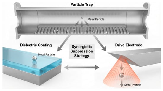
Figure 4.
Coordinated Mitigation Approach. Adapted from reference [50].
Furthermore, it is noteworthy that current research has predominantly focused on two aspects: the adverse effects of metallic particles on surface charge accumulation, and methods for mitigating or suppressing metallic particle motion within GIE. However, there is a lack of direct evidence demonstrating how such mitigation improves the surface charge accumulation characteristics of insulators. Further systematic investigation in this area is therefore necessary.
The limitations of existing studies can be summarized as follows:
- (i)
- Most experiments simulate the non-uniform electric field in DC GIL using plate or wedge electrodes, with few employing coaxial electrode structures that closely resemble the configuration of actual DC GIE.
- (ii)
- Existing models of particle motion often oversimplify particles as point charges or perfect spheres, neglecting the influence of particle shape, surface properties, and charge distribution on their motion, which limits the accuracy and reliability of these models.
- (iii)
- Studies on the impact of metallic particles on surface flashover are mostly confined to macroscopic evaluations—such as the influence of particle size and trajectory on flashover voltage—with limited exploration of the underlying mechanisms by which particles damage insulation and initiate flashover.
Therefore, it is essential to further refine the analytical methods for particle charging and force analysis, as well as the simulation models of particle dynamics, to accurately predict metallic particle trajectories and improve the design of mitigation strategies.
In summary, although existing studies have made significant progress in revealing the motion mechanisms of metallic particles, most simulation and experimental models still rely on evident simplifying assumptions, limiting their direct extrapolation to real GIE systems. On one hand, many particle motion models simplify metallic particles as point charges or ideal spheres, neglecting the influence of actual particle irregularity, surface oxide layers, non-uniform charge distribution, and other factors on trajectory and collision behavior. On the other hand, experimental setups often employ plate-plate, wedge-shaped, or simplified coaxial electrode configurations to simulate non-uniform electric fields. While these can reflect certain physical mechanisms, they hardly fully replicate the complex three-dimensional electric field distribution, insulator geometry, and multi-physics coupling effects present in actual GIE. Furthermore, particle sizes, material types, and motion ranges under laboratory conditions are typically standardized or simplified, differing from the diversity of contaminants, size distributions, and particle aging behaviors that may occur in real equipment during long-term operation. Therefore, when applying current research findings to guide actual GIE insulation design and particle suppression strategies, validation and refinement through full-scale equipment tests or higher-fidelity multi-physics coupled simulations remain necessary.
3. New Challenges in Adopting Eco-Friendly Insulating Gases
SF6 is a potent greenhouse gas (GHG) with a global warming potential (GWP) 23,500 times that of CO2 and an atmospheric lifetime of 3200 years. Even minor SF6 leaks can cause irreversible environmental harm. Although SF6 remains the most effective insulating medium for GIE applications, its severe greenhouse effect necessitates strict limitations and a gradual phase-out in the power industry. Therefore, the introduction of eco-friendly insulating gases into GIE to reduce SF6 usage is of strategic importance for mitigating global warming—a concern widely recognized by the electrical equipment sector worldwide.
3.1. Major Eco-Friendly Insulating Gases and Their DC Insulation Performance
3.1.1. Types and Physicochemical Properties of Major Eco-Friendly Insulating Gases
Currently, promising eco-friendly insulating gases can be categorized as follows:
- Common gases, such as N2, CO2, and dry air;
- SF6-based gas mixtures, such as SF6/N2 and SF6/CF4;
- Perfluorocarbons, including CF4, C3F8, and c-C4F8;
- Various electronegative gases, such as CF3I, C4F7N, C5F10O, C6F12O, and HFO-1234ze(E) [51,52]. Table 2 summarizes the fundamental parameters of major eco-friendly insulating gases compared with SF6 [53,54].
Table 2. Fundamental Parameters of Major Eco-Friendly Insulating Gases and SF6. Summarized from references [53,54].
Conventional gases possess inherent advantages such as high stability, low liquefaction temperature, low cost, and excellent environmental friendliness. However, their intrinsic insulation performance is generally inadequate for application in high-voltage equipment. Although SF6 gas mixtures exhibit superior overall performance, their decomposition behavior is more complex than that of pure SF6. This complexity, along with concerns regarding biocompatibility and challenges in online gas composition monitoring, poses difficulties for their practical application [55,56]. Perfluorocarbons offer high dielectric strength and favorable biosafety, yet they typically suffer from high liquefaction temperatures and a significant drop in insulation strength when mixed with buffer gases. Moreover, their inherently high GWP values imply greater environmental impact compared to other eco-friendly insulating gases. Overall, these gases demonstrate no distinct advantage as eco-friendly alternatives and have seen virtually no practical application to date.
The C4F7N gas proposed by 3M Company exhibits a dielectric strength approximately twice that of SF6, with the added advantages of low tendency for solid by-product formation and good compatibility with metallic and non-metallic materials within equipment. In 2016, General Electric (GE) and 3M jointly launched the first 420 kV/63 kA eco-friendly GIE, which used a gas mixture of 4% C4F7N/96% CO2 as the insulating medium. Furthermore, GE introduced a 145 kV GIE insulated with a mixture of 6% C4F7N/89% CO2/5% O2 at a pressure of 0.85 MPa [57]. In 2022, China’s first 110 kV C4F7N-based eco-friendly GIE was successfully put into operation at the 110 kV Ningguo Substation in Shanghai. These developments indicate that C4F7N is currently one of the most promising eco-friendly insulating gases with potential for large-scale application. Therefore, the following section will focus on the DC insulation performance of C4F7N and its gas mixtures.
3.1.2. DC Breakdown Characteristics of C4F7N Gas Mixtures
The ability to withstand gap breakdown is a fundamental indicator of the insulation performance of a gas. Tu et al. investigated the DC breakdown characteristics of C4F7N mixtures under slightly non-uniform electric fields, as illustrated in Figure 5 [58,59]. Experimental results show that at 0.7 MPa, the negative DC breakdown field strength of 4% C4F7N/96% CO2 and 8% C4F7N/92% CO2 mixtures reaches 81.21% and 96.5%, respectively, of that of pure SF6 at 0.5 MPa. Under identical conditions, the DC gap breakdown performance of C4F7N/CO2 mixtures surpasses that of C4F7N/N2 mixtures [60,61]. Furthermore, repeated DC breakdown tests on C4F7N/N2 mixtures tend to cause solid by-product deposition on electrode surfaces [62], indicating that CO2 is a more suitable buffer gas for C4F7N.
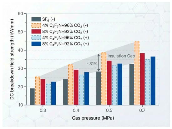
Figure 5.
DC Breakdown Characteristics of C4F7N/CO2 under Quasi-Uniform Electric Field. Adapted from references [58,59].
Additional experiments were conducted under highly non-uniform electric fields [58], revealing that the negative DC breakdown voltage of C4F7N/CO2 mixtures exceeds the positive DC breakdown voltage. Moreover, the negative breakdown voltage increases with rising gas pressure, whereas the positive breakdown voltage shows the opposite trend. This indicates a significant polarity effect in the DC breakdown characteristics of C4F7N/CO2 mixtures under highly non-uniform electric fields.
Li et al. employed free metallic particles to modulate the degree of local electric field distortion, thereby investigating the sensitivity of the DC breakdown voltage of C4F7N/CO2 mixtures to electric field variations [63]. In the absence of metallic particles, the DC gap breakdown voltage of the C4F7N/CO2 mixture reached a level comparable to that of SF6/N2. Under conditions with metallic particles present, however, the breakdown voltage of the C4F7N/CO2 mixture exceeded that of SF6/N2. These findings demonstrate that the C4F7N/CO2 mixture not only exhibits excellent DC insulation performance but also shows low sensitivity to particle-induced discharge.
In summary, C4F7N/CO2 gas mixtures exhibit excellent gap breakdown performance under DC voltage, meeting the fundamental insulation requirements for GIE equipment. The extensive data available from existing studies provide valuable references for the development of DC GIE. However, it is noteworthy that the insulation performance of C4F7N/CO2 mixtures at high gas pressure is moderately inferior to that of SF6. Consequently, the design of DC GIE may need to consider increasing the equipment volume or gas pressure to enhance its insulation capacity.
3.1.3. Impulse and Surface Flashover Characteristics of C4F7N Gas Mixtures
The insulation design of GIE must account for the effects of lightning or switching impulse voltages, with the gas–solid interface being the most vulnerable part of the internal insulation. Nechmi et al. from the SuperGrid Institute, France, measured the lightning impulse characteristics of a C4F7N/CO2 mixture [64]. Under a slightly non-uniform electric field, the lightning impulse performance of a 3.7% C4F7N/96.3% CO2 mixture at 0.88 MPa and 1.04 MPa reached the level of SF6 at 0.55 MPa and 0.65 MPa, respectively, though this equivalence did not hold under a highly non-uniform field. The negative lightning impulse withstand level was higher than the positive level and increased more significantly with rising gas pressure.
Kieffel et al. reported that the negative lightning impulse breakdown voltage of 4–10% C4F7N/CO2 mixtures at 0.67–0.82 MPa reached 87%–96% of that of SF6 at 0.55 MPa [65]. Zhang et al. from Xi’an Jiaotong University investigated the lightning impulse characteristics of C4F7N/CO2 mixtures under varying degrees of electric field non-uniformity, as shown in Figure 6. Experiments revealed that under slightly non-uniform fields, the U50 of the gas mixture increased in an approximately linear manner with gas pressure [66]. Furthermore, U50 decreased markedly as the field non-uniformity increased, indicating that highly non-uniform electric fields should be avoided as much as possible in the design of HVDC GIE.
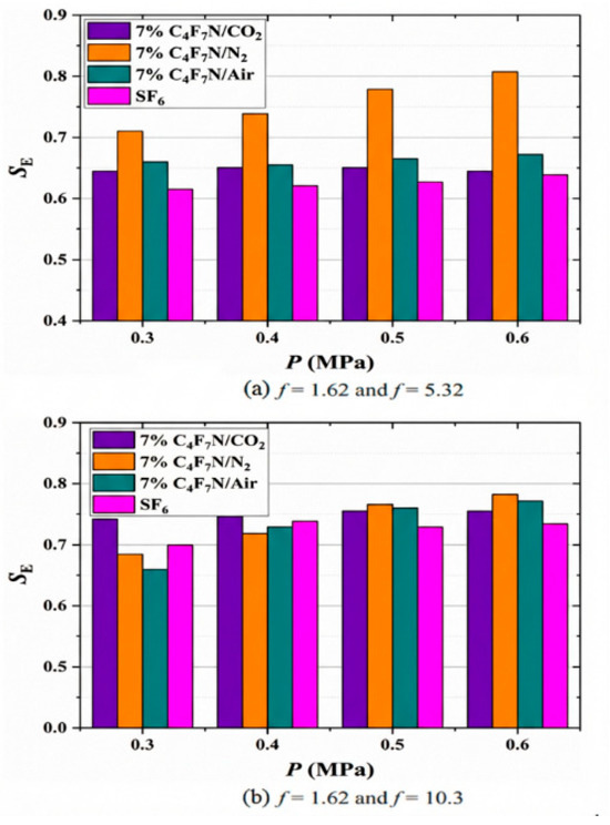
Figure 6.
Sensitivity of C4F7N/CO2 Lightning Impulse Characteristics to Electric Field. Adapted from reference [66].
Chen et al. [67] investigated the DC surface flashover characteristics of C4F7N/CO2 mixtures. Their experiments showed that the negative DC flashover voltage of a 4% C4F7N/96% CO2 mixture at 0.7 MPa reached 96.06% of that of SF6 at 0.5 MPa. When the mixing ratio was increased to 8%, this value rose to 101.50%. Furthermore, the negative DC flashover voltage of the 4% C4F7N mixture was higher than its positive DC flashover voltage, whereas the 8% C4F7N mixture exhibited the opposite behavior—its negative flashover voltage was lower than the positive value. This indicates a notable polarity effect in the DC flashover performance of these gas mixtures.
Overall, existing studies on the lightning impulse and surface flashover characteristics of C4F7N/CO2 mixtures remains relatively limited. Given that surface flashover is one of the more frequent insulation failures in high-voltage electrical equipment, it is essential to conduct fundamental flashover tests on full-scale prototype equipment in the future. Such studies will ensure that the gas mixtures meet the necessary insulation design requirements for DC GIE.
3.2. Influence of Insulating Gas Environment on Charge Accumulation
Zhang et al. from Xi’an Jiaotong University measured the surface charge accumulation characteristics on insulators under DC voltage in C4F7N/CO2 mixtures, as shown in Figure 7 [68]. The experimental results indicated that the insulator surface was predominantly populated with homopolar charges. However, the surface charge density in the 25% C4F7N/CO2 mixture was significantly higher than that in SF6. This observed higher charge density may be related to the more intense partial discharge activity in the C4F7N/CO2 mixture. Tu et al. from North China Electric Power University reported similar experimental findings [69]. To mitigate the risk of reduced flashover voltage caused by heteropolar charges in gas mixtures, researchers recommend increasing both the C4F7N content and the gas pressure when applying eco-friendly gases in DC GIE.
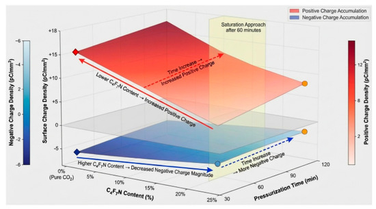
Figure 7.
Surface Charge Accumulation Characteristics under C4F7N/CO2 Mixture. Adapted from reference [68].
Dong et al. from Xi’an Jiaotong University identified three distinct patterns of surface charge distribution in C4F7N/CO2 mixtures: a homopolar charge region near the high-voltage electrode, heteropolar charge patches adjacent to the high-voltage conductor, and randomly distributed cloud-like bipolar charge patches on the insulator surface, as illustrated in Figure 8 [70]. With increasing C4F7N content, both the charge density and the spatial extent of the charge patches increased. This trend is attributed to the higher electric field sensitivity of C4F7N/CO2 mixtures compared to SF6, which enhances gas-side ionization and leads to a greater influx of heteropolar charges from the gas phase.
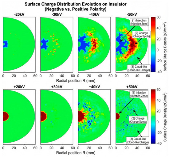
Figure 8.
Surface Charge Distribution Patterns under C4F7N/CO2 Mixture. Adapted from reference [70].
Table 3 compares the surface charge accumulation characteristics of the C4F7N mixed gas and SF6. And Table 4 compares the effects of metal particles under different field configurations.
Table 3.
Comparison of surface charge accumulation characteristics in C4F7N mixtures and SF6. Summarized from references [68,70].
Table 4.
Influence of metallic particles under different electric field configurations. Summarized from references [67,68,69,70].
The aforementioned studies reveal distinct differences between C4F7N/CO2 mixtures and SF6 in terms of both the pattern and magnitude of surface charge accumulation on insulators. The primary reason for this discrepancy lies in the higher electric field sensitivity of the gas mixture, which promotes gas-side ionization under the same voltage level, thereby intensifying surface charge accumulation. Furthermore, research on surface charge accumulation under DC conditions—particularly on full-scale basin-type insulators—remains relatively limited. Given that surface charge is a critical factor triggering surface flashover under DC voltage, future work should not only delve deeper into the characteristics of surface charge accumulation in C4F7N/CO2 mixtures but also clarify the relationship between charge accumulation and flashover initiation. Elucidating the mechanism of charge-induced flashover is essential to providing reliable guidance for the insulation design of DC GIE.
4. Experimental Methods for HVDC GIE
Currently, the prototype assessment methods for HVDC GIE and the type test standards for insulation components are primarily adapted from those used for AC GIE. To ensure the safe and reliable operation of final GIE products, researchers have initiated studies on the development and type testing of HVDC GIE. By investigating methods and theories for verifying DC insulation reliability, they aim to establish dedicated assessment techniques and evaluation criteria specifically for HVDC GIE.
Since the 1990s, equipment manufacturers worldwide have conducted research on long-term energized tests for HVDC GIE. In 2014, the International Council on Large Electric Systems (CIGRÉ) issued recommendations concerning dielectric insulation performance tests for GIE, emphasizing that gas-insulated equipment must comply with the electrical and mechanical performance limits specified in IEC 62271, which are independent of the type of operating voltage [15,71]. In 2018, Siemens [72] completed the test validation for a ±550 kV HVDC GIE prototype. The test protocol, summarized in Table 5, included dielectric performance tests, long-term energized tests under both positive and negative polarities, and overvoltage tests under both polarities.
Table 5.
Long-Term Energized Test Protocol for GIE by Siemens. Summarized from reference [72].
In China, leading electrical equipment manufacturers have also embarked on research concerning energized testing protocols for GIE. Representative work by Yao et al. from Xi’an XD Switchgear Electric Co., Ltd. (Xikai), drawing on the CIGRÉ technical brochure [9], established a comprehensive long-term energized test sequence for a ±550 kV GIE prototype. The test items encompassed sealing and micro-water content verification, power-frequency withstand voltage combined with partial discharge measurement, and DC superimposed impulse voltage tests. The entire validation procedure was organized into six consecutive test cycles, systematically evaluating the prototype’s dielectric integrity under both positive and negative polarities at the rated withstand voltage, at 1.2 times this value, and under rated voltage during high-load operation, as detailed in Table 6 [9].
Table 6.
Long-Term Energized Test Protocol for GIE by Xikai. Summarized from reference [9].
Shen et al. from the Xi’an High Voltage Apparatus Research Institute, with reference to the Chinese national standards GB/T 25091-2010 (High-voltage DC disconnectors and earthing switches) and GB/T 36498-2018 (Guide for insulation coordination of VSC-HVDC converter stations) [10], evaluated the insulation performance of a ±550 kV GIE prototype under both rated voltage and 1.2 times the rated voltage. Based on the DC superimposed impulse voltage tests, they designed a critical test circuit, as illustrated in Figure 9.
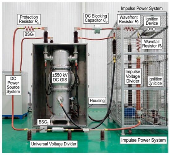
Figure 9.
Test Circuit for Superimposed Impulse Voltage. Adapted from reference [10].
Currently, the application of eco-friendly insulating gases in electrical equipment is becoming increasingly widespread. However, specialized test methods and standardized systems tailored to their characteristics remain underdeveloped. Existing national and international standards are still predominantly based on conventional SF6, leading to several critical challenges in the testing of eco-friendly gas-insulated equipment. These include compatibility with equipment materials, criteria for temperature rise/thermal stability, partial discharge monitoring thresholds, and standards and indicators for decomposition product monitoring—all of which require extensive fundamental and engineering research.
In summary, although several HVDC GIE prototypes have been put into trial operation, there is currently no universally accepted procedure or standard for assessing equipment insulation performance. Some manufacturers have primarily conducted type tests in the following areas: voltage withstand tests under rated load, temperature rise tests, impulse tests, DC superimposed impulse tests, and mechanical stress tests. Determining how to effectively test GIE products before they leave the factory remains a topic for further research. In particular, the development of type test methods for DC gas-insulated equipment will not only help evaluate the reliability of insulation design but also provide essential data for refining insulation design methodologies. It should be noted that current test methods are mostly based on standardized samples or simplified models. The scalability of laboratory results to full-scale, multi-condition GIE equipment requires further consideration of size effects, long-term electro-thermal-mechanical stresses, and metal particle contamination in real service environments. Future work should strengthen the transition from laboratory models to engineering prototype verification, establishing test evaluation systems that better reflect actual operating conditions.
5. Conclusions and Prospects
With the progressive expansion of offshore wind power into far-sea areas, HVDC transmission systems have demonstrated significant advantages in cost, efficiency, and applicability. The development of HVDC GIE is therefore of great importance for optimizing national energy allocation and facilitating the transition to renewable energy. Nevertheless, the insulation design of DC gas-insulated equipment, particularly HVDC GIE, still faces multiple challenges. This paper has reviewed key issues including metallic charged particles and their mitigation methods, new challenges associated with the introduction of eco-friendly insulating gases, and experimental methods for HVDC GIE. The main conclusions and future prospects are summarized as follows:
Most existing particle motion models and experimental systems rely on simplified assumptions. Future research should, therefore, develop higher-fidelity multi-physics coupled simulation platforms to study the dynamic interaction between particle motion and surface charge accumulation. Furthermore, it is necessary to conduct research on particle motion in real GIE setups and to further optimize the analytical methods for particle charging and force analysis, as well as the simulation models of the motion process. This will enable the effective prediction of metallic particle trajectories and guide the formulation of mitigation strategies. Moreover, since single particle suppression measures can hardly achieve complete control, the synergistic application of multiple methods is required in future work.
Building on this, experimental studies have shown that metallic and non-metallic particles inside GIE can acquire charge during motion, significantly promoting surface charge accumulation. While the direct quantitative link to flashover voltage reduction requires further validation, prevailing theoretical models support that such accumulation is a key precursor to surface flashover. However, research on the coupled interaction between these moving charged particles and charge accumulation on insulators remains scarce. Consequently, future work should systematically investigate the influence of particle dynamics—including motion and adhesion—on charge accumulation behavior at the gas–solid interface, aiming to establish a quantitative link between particle activity, charge accumulation patterns, and flashover voltage reduction.
Beyond the fundamental mechanisms, a practical bottleneck exists. Current test methods for HVDC GIE are still insufficient, and relevant testing evaluation technologies and standards are lacking. Subsequent efforts should, therefore, further improve various type test methods for HVDC GIE and establish standards related to long-term energized performance assessment.
Looking towards sustainable development, introducing eco-friendly insulating gases into HVDC GIE is crucial for achieving the “Dual Carbon” goals. In this context, follow-up research should accelerate basic insulation performance experiments, including full-scale HVDC tests for C4F7N/CO2 mixtures with particular attention to surface flashover characteristics. Moreover, studies should focus on modeling the long-term insulation stability in the presence of eco-friendly gases and metallic contaminants, while exploring design optimizations to enhance the insulation withstand capability.
Author Contributions
B.T.: Conceptualization (lead); Methodology (lead); Funding acquisition (lead); Literature search & screening (supporting); Writing—original draft (lead); Writing—review & editing (supporting). Y.X.: Literature search & screening (lead); Data extraction (lead); Formal analysis (supporting); Visualization (lead). R.Z.: Formal analysis (lead); Interpretation (lead); Visualization (supporting); Writing—review & editing (supporting). J.T.: Resources (supporting); Supervision (lead); Writing—review & editing (lead). All authors have read and agreed to the published version of the manuscript.
Funding
This study is supported by National Engineering Research Center of UHV Technology and New Electrical Equipment Basis, China [grant ID: NERCUHE-2024-KF-08].
Institutional Review Board Statement
Not applicable.
Informed Consent Statement
Not applicable.
Data Availability Statement
The data that support the findings of this study are available from the corresponding author upon reasonable request.
Conflicts of Interest
The authors have no conflicts to disclose.
References
- Yang, B.; Liu, B.; Zhou, H.; Wang, J.; Yao, W.; Wu, S.; Shu, H.; Ren, Y. A critical survey of technologies of large offshore wind farm integration: Summary, advances, and perspectives. Prot. Control. Mod. Power Syst. 2022, 7, 233–264. [Google Scholar] [CrossRef]
- Korompili, A.; Wu, Q.; Zhao, H. Review of VSC HVDC connection for offshore wind power integration. Renew. Sustain. Energy Rev. 2016, 59, 1405–1414. [Google Scholar] [CrossRef]
- Cai, X.; Yang, R.; Zhou, J.; Fang, Z.; Yang, M.; Shi, X.; Chen, Q. Review on offshore wind power integration via DC transmission. Autom. Electr. Power Syst. 2021, 45, 2–22. [Google Scholar]
- Wang, Q.; Yao, W.; Fang, J.; Ai, X.; Yang, X.; Xie, H.; Huang, X. Dynamic modeling and small signal stability analysis of distributed photovoltaic grid-connected system with large scale of panel level DC optimizers. Appl. Energy 2020, 259, 114132. [Google Scholar] [CrossRef]
- Song, D.; Shen, G.; Huang, C.; Huang, Q.; Yang, J.; Dong, M.; Joo, Y.H.; Duić, N. Review on the application of artificial intelligence methods in the control and design of offshore wind power systems. J. Mar. Sci. Eng. 2024, 12, 424. [Google Scholar] [CrossRef]
- Li, Z.; Guo, X.; Shen, X.; Tang, H. Summary of technologies for the development of offshore wind power industry in China. Power Gener. Technol. 2022, 43, 186–197. [Google Scholar]
- Zhao, G.; Chen, W.; Deng, Z.; Yu, H.; Xu, Y.; Zhao, Z. Key technologies and application of flexible low-frequency AC transmission. Autom. Electr. Power Syst. 2022, 46, 1–10. [Google Scholar]
- Sun, Q.; Luo, C.; Wang, F.; Chen, S.; Chen, J.; Zhou, Z.; Wang, L. Overview on the surface flashover of basin-type insulator in UHV GIS. High Volt. Appar. 2018, 54, 17–25, 32. [Google Scholar]
- Yao, X.; Nan, Z.; Du, W.; Zhang, B.; Li, Y. Study on long-term live test for ±550 kV DC gas insulated switchgear. Electr. Eng. 2024, 25, 46–52. [Google Scholar]
- Shen, M.; Wang, B.; Wang, Z.; Li, J.; Su, C.; Li, Q.; Liu, C.; Du, W.; Nan, Z. Analysis on long term live test of ±550 kV DC GIS. Electr. Eng. 2024, 60, 1–11. [Google Scholar]
- Li, Y.; Zhang, X.; Fu, M.; Xiao, S.; Tang, J.; Tian, S. Research and application progress of eco-friendly gas insulating medium C4F7N, part I: Insulation and electrical, thermal decomposition properties. Trans. China Electrotech. Soc. 2021, 36, 3535–3552. [Google Scholar]
- Li, Y.; Zhang, X.; Fu, M.; Xiao, S.; Tang, J.; Tian, S. Research and application progress of eco-friendly gas insulating medium C4F7N, part II: Material compatibility, safety and equipment development. Trans. China Electrotech. Soc. 2021, 36, 4567–4579. [Google Scholar]
- Chen, G.; Guo, C.; Li, P.; Feng, Y.; Ge, D.; Zhang, P.; Huang, H.; Xu, Y. Review on Insulation Reliability Improvement of EHV/UHV GIS. High Volt. Electr. Equip. 2024, 61, 1–16. [Google Scholar]
- Dong, M.; Zang, C.; Zhan, Z.; Xin, W. Research Progress on Metal Particle Issues Inside GIL. High Volt. Electr. Appar. 2024, 60, 1–14. [Google Scholar]
- Zhang, C.; Zhang, B.; Li, M.; Li, Y.; Li, X.; Lv, J.; Wang, Z.; Li, W.; Yang, X. Review of Key Insulation Technologies of HVDC GIL. High Volt. Eng. 2023, 49, 920–936. [Google Scholar]
- Li, J.; Yang, L.; Yu, J. Review on Metal Particle Contamination in GIS/GIL Equipment. Electrotech. Electr. 2022, 3, 1–7. [Google Scholar]
- Li, Q.; Wang, J.; Li, B.; Liu, S.; Chen, C.; Li, C. Review on Metal Particle Contamination in GIS/GIL. High Volt. Eng. 2016, 42, 849–860. [Google Scholar]
- Wang, J. Research on the Moving Mechanisms of Charged Metal Particles in DC GIL and Suppressing Methods. Ph.D. Thesis, North China Electric Power University, Beijing, China, 2017. [Google Scholar]
- Li, T. Research on Particle Motion Characteristics and Trap Capture Effect Improvement in Communication GIS. Master’s Thesis, Nanchang University, Nanchang, China, 2024. [Google Scholar]
- Ma, K. Research on Dynamic Characteristics and Treatment Methods of Metal Particles Dust in DC GIS/GIL. Ph.D. Thesis, North China Electric Power University, Beijing, China, 2023. [Google Scholar]
- Liu, H. Research on Motion and Inhibition of Spherical Metal Particles in SF6, Gas Under DC Voltage. Ph.D. Thesis, North China Electric Power University, Beijing, China, 2018. [Google Scholar]
- Luo, C. Research on Motion Behavior and Characteristics of Metal Particle in DC GIS. Master’s Thesis, Hunan University, Changsha, China, 2019. [Google Scholar]
- Yang, L. Analysis of Particle Motion and Related Suppression Measures in GIS/GIL Under DC Voltage. Master’s Thesis, North China Electric Power University, Beijing, China, 2020. [Google Scholar]
- Wang, F.; Cao, D.; Yang, L.; Liu, H.; Li, Z.; Qi, Y. Effect of Particle Traps on Movement of Spherical Free-conducting Particles in Slightly Inhomogeneous DC Field. High Volt. Eng. 2018, 44, 2897–2903. [Google Scholar]
- Yao, Y.; Pan, C.; Tang, J.; Luo, X.; Xia, S. Motion Behaviors and Partial Discharge Characteristics of Metallic Particles in Moving Transformer Oil under AC/DC Composite Voltage. Trans. China Electrotech. Soc. 2021, 36, 3101–3112. [Google Scholar]
- Zhang, Q.; Jia, J.; Yang, L.; Yuan, Y. Charging Mechanism of Metallic Conducting Particle on a Dielectrically Coated Electrode in Gas Insulated System. J. Xi’an Jiaotong Univ. 2005, 38, 1287–1291. [Google Scholar]
- Jia, J.; Tao, F.; Yang, L.; Zhang, Q. Motion Analysis of Spherical Free Conducting Particle in Non-uniform Electric Field of GIS Under DC Voltage. Proc. CSEE 2006, 26, 106–111. [Google Scholar]
- Jia, J.; Chen, S.; Yang, L.; Zhang, Q. Study of Deactivation of Free Conducting Particle near Spacer in GIS. High Volt. Appar. 2004, 40, 370–372. [Google Scholar]
- Lebedev, N.; Skal, I. Force acting on a conducting sphere in the field of a parallel plane condenser. Sov. Phys. Tech. Phys. 1962, 7, 268–270. [Google Scholar]
- Wenger, P.; Beltle, M.; Tenbohlen, S.; Riechert, U.; Behrmann, G. Combined characterization of free-moving particles in HVDC-GIS using UHF PD, high-speed imaging, and pulse-sequence analysis. IEEE Trans. Power Deliv. 2019, 34, 1540–1548. [Google Scholar] [CrossRef]
- Cheng, H.; Wei, W.; Bilallqbal, A.; Sun, Y.; Zhang, L. Study on the Electrodynamic Behavior of Linear Metal Particles in DC Gas Insulated Transmission Line. Trans. China Electrotech. Soc. 2021, 36, 5283–5293. [Google Scholar]
- Chang, Y.; Geng, Q.; Hu, Z.; Li, Q. Physical Mechanism and Critical Starting Criterion of Wire Particle Firefly Movement under DC Electric Stress. Trans. China Electrotech. Soc. 2023, 38, 648–658. [Google Scholar]
- Hu, Z.; Wei, L.; Geng, Q.; Wang, J.; Li, Q.; Chang, Y. Firefly Movement Phenomenon of Wire Particle Swarm and Risk Assessment in DC GIS/GIL. Proc. CSEE 2024, 44, 6219–6229. [Google Scholar]
- Wang, J.; Hu, Q.; Chang, Y.; Wnag, J.; Liang, R.; Tu, Y. Metal particle contamination in gas-insulated switchgears/gas-insulated transmission lines. CSEE J. Power Energy Syst. 2021, 7, 1011–1025. [Google Scholar]
- Iwabuchi, H.; Matsuoka, S.; Kumada, A.; Hidaka, K.; Hoshina, Y.; Yasuoka, T. Influence of tiny metal particles on charge accumulation phenomena of GIS model spacer in high-pressure SF6 gas. IEEE Trans. Dielectr. Electr. Insul. 2013, 20, 1895–1901. [Google Scholar] [CrossRef]
- Zhang, B.; Qi, B.; Zhang, G. Charge accumulation patterns on spacer surface in HVDC gas-insulated system: Dominant uniform charging and random charge speckles. IEEE Trans. Dielectr. Electr. Insul. 2017, 24, 1229–1238. [Google Scholar] [CrossRef]
- Wang, Z.; Wang, J.; Li, Q.; Liu, S. 3D Simulation and Experimental Study of Metal Particles’ Effect in DC GIL on Surface Charge Accumulation. Proc. CSEE 2016, 36, 6718–6726,6925. [Google Scholar]
- Gao, Y.; Li, Z.; Wang, H.; Yuan, X. Metal Particle Encouraged Surface Charge Accumulation on Epoxy Insulator with Multi-Arc Surface Profile under DC Voltage. IEEE Trans. Dielectr. Electr. Insul. 2020, 27, 998–1006. [Google Scholar] [CrossRef]
- Gao, Y.; Wang, H.; Yuan, X.; Zhao, H.; Li, Z. Surface Charge Accumulation on a Real Size Epoxy Insulator with Bouncing Metal Particle Under DC Voltage. IEEE Trans. Plasma Sci. 2021, 49, 2166–2175. [Google Scholar] [CrossRef]
- Xing, Y.; Sun, X.; Yang, Y.; Mazzanti, G.; Fabiani, D.; He, J.; Li, C. Metal particle induced spacer surface charging phenomena in direct current gas-insulated transmission lines. J. Phys. D-Appl. Phys. 2021, 54, 34LT03. [Google Scholar]
- Li, X.; Dan, S.; You, W.; Wu, M. Review of Particle Trap in SF6 Gas Insulated Apparatus. High Volt. Appar. 2013, 49, 150–154. [Google Scholar]
- Lü, F.; Zhao, Z.; Zhan, Z.; Ma, K. Research Development of Treatment Method for Metal Particles in GIL. Guangdong Electr. Power 2020, 33, 94–109. [Google Scholar]
- Asano, K.; Anno, K.; Higashiyama, Y. The behavior of charged conducting particles in electric fields. IEEE Trans. Ind. Appl. 1997, 33, 679–686. [Google Scholar]
- Okabe, S.; Ueta, G.; Utsumi, T. Behavior of metallic particles in GIS under DC voltage. IEEE Trans. Dielectr. Electr. Insul. 2015, 22, 2889–2897. [Google Scholar] [CrossRef]
- Sakai, K.I.; Abella, D.L.; Khan, Y.; Suehiro, J.; Hara, M. Experimental studies of free conducting wire particle behavior between nonparallel plane electrodes with AC voltages in air. IEEE Trans. Dielectr. Electr. Insul. 2003, 10, 418–424. [Google Scholar] [CrossRef]
- Ni, X.; Wang, J.; Wang, J.; Wang, Z.; Li, Q. Polarity Effect of DC GIL Electrode Coating on Particle Inhibition. High Volt. Eng. 2018, 44, 2695–2703. [Google Scholar]
- Chang, Y.; Wang, J.; Li, Q.; Li, Z.; He, J.; Bian, Y. Research Progress of Particle Contamination Suppression Measures in AC and DC Gas-insulated Transmission Equipment. High Volt. Appar. 2021, 57, 91–100, 110. [Google Scholar]
- Liu, S. Control of metal chips in SF6 gas insulated electrical appliances. High Volt. Appar. 1989, 25, 35–43. [Google Scholar]
- Wang, J.; Ni, X.; Wang, Z.; Li, Q.; Li, C. Trapping Probability and Designing Optimization of Particle Trap in DC GlL. High Volt. Eng. 2018, 44, 4090–4097. [Google Scholar]
- Chang, Y. Physical Mechanism and Synergistic Suppression Method of Metal Particle Firefly in GIL. Ph.D. Thesis, North China Electric Power University, Beijing, China, 2023. [Google Scholar]
- Kline, L.; Davies, D.; Chen, C.; Chantry, P.J. Dielectric properties for SF6 and SF6 mixtures predicted from basic data. J. Appl. Phys. 1979, 50, 6789–6796. [Google Scholar] [CrossRef]
- Li, X.; Zhao, H. Review of Research Progress in SFs Substitute Gases. High Volt. Eng. 2016, 42, 1695–1701. [Google Scholar]
- Kumar, S.; Sanjay, S.; Yadav, B.P.; Varadharajan, S. Environmental Impact of SF6 and Investigation of Its Substitute: A Review. Adv. Ind. Saf. Sel. Proc. HSFEA 2018, 2020, 233. [Google Scholar]
- Pan, B.F.; Wang, G.M.; Shi, H.M.; Shen, J.; Ji, H.K.; Kil, G.S. Green Gas for Grid as an Eco-Friendly Alternative Insulation Gas to SF6: A Review. Appl. Sci. 2020, 10, 2526. [Google Scholar] [CrossRef]
- Vial, L.; Casanovas, A.; Coll, I.; Casanovas, J. Decomposition products from negative and 50 Hz ac corona discharges in compressed SF6 and SF6/N2 (10:90) mixtures. Effect of water vapour added to the gas. J. Phys. D Appl. Phys. 1999, 32, 1681. [Google Scholar]
- Clavreul, R. Analysis of SF6/N2 gas mixture decomposition by-products in electric discharges. In Proceedings of the Seventh International Conference on Dielectric Materials, Measurements and Applications F, Bath, UK, 23–26 September 1996; IET: Edison, NJ, USA, 1996. [Google Scholar]
- Meyer, F.; Kieffel, Y. Application of Fluoronitrile/CO2/O2 Mixtures in High Voltage Products to Lower the Environmental Footprint; CIGRE Reports: Paris, France, 2018. [Google Scholar]
- Tu, Y.; Cheng, Y.; Wang, C.; Ai, X.; Zhou, F.; Chen, G. Insulation characteristics of fluoronitriles/CO2 gas mixture under DC electric field. IEEE Trans. Dielectr. Electr. Insul. 2018, 25, 1324–1331. [Google Scholar] [CrossRef]
- Wang, C.; Cheng, Y.; Tu, Y.; Chen, G.; Yuan, Z.; Xiao, A. Characteristics of C3F7CN/CO2 as an alternative to SF6 in HVDC-GIL systems. IEEE Trans. Dielectr. Electr. Insul. 2018, 25, 1351–1356. [Google Scholar]
- Tu, Y.; Ai, X.; Cheng, Y.; Jin, H.; Wang, C. DC Breakdown Characteristics of C3F7CN/N2 Gas Mixtures. Trans. China Electrotech. Soc. 2018, 33, 5189–5195. [Google Scholar]
- Zhang, Y.; Chen, Q.; Zhang, H.; Li, Y.; Zhang, J.; Xiao, S. Insulation Performance of C3F7CN/CO2 Gas Mixtures in Quasi-Uniform Electric Field. High Volt. Eng. 2018, 44, 3158–3164. [Google Scholar]
- Zheng, Y.; Zhou, W.; Li, H.; Yan, X.; Li, Z.; Chen, W. Influence of conductor surface roughness on insulation performance of C4F7N/CO2 mixed gas. IEEE Trans. Dielectr. Electr. Insul. 2019, 26, 922–929. [Google Scholar]
- Wang, J.; Wang, J.; Ni, X.; Wang, C.; Li, Q. Comparative Analysis of Discharge Sensitivity by the Free Spherical Aluminum Particle in C4F7N/CO2 and SF6/N2 Gas Mixtures under DC Electric Field. Trans. China Electrotech. Soc. 2018, 33, 4682–4691. [Google Scholar]
- Nechmi, H.E.; Beroual, A.; Girodet, A.; Vinson, P. Fluoronitriles/CO2 gas mixture as promising substitute to SF6 for insulation in high voltage applications. IEEE Trans. Dielectr. Electr. Insul. 2016, 23, 2587–2593. [Google Scholar] [CrossRef]
- Kieffel, Y.; Irwin, T.; Ponchon, P.; Owens, J. Green gas to replace SF6 in electrical grids. IEEE Power Energy Mag. 2016, 14, 32–39. [Google Scholar] [CrossRef]
- Song, J.; Li, X.; Zhang, Q.; Lv, Y.; Yuan, X.; Li, Z. Sensitivity of dielectric strength of C4F7N binary gas mixture to electric field distribution under lightning impulse. IEEE Trans. Dielectr. Electr. Insul. 2020, 27, 1152–1159. [Google Scholar] [CrossRef]
- Chen, G.; Tu, Y.; Wang, C.; Wang, J.; Yuan, Z.; Ma, G. Environment-friendly insulating gases for HVDC gas-insulated transmission lines. CSEE J. Power Energy Syst. 2019, 7, 510–529. [Google Scholar]
- Zhang, B.; Li, X.; Wang, T.; Zhang, G. Surface charging characteristics of GIL model spacers under DC stress in C4F7N/CO2 gas mixture. IEEE Trans. Dielectr. Electr. 2020, 27, 597–605. [Google Scholar]
- Chen, G.; Tu, Y.; Wu, S.; Lin, C.; Qin, S.; Li, C.; He, J. Intrinsic hetero-polar surface charge phenomenon in environmental friendly C3F7CN/CO2 gas mixture. J. Phys. D Appl. Phys. 2020, 53, 18LT03. [Google Scholar]
- Dong, J.; Chen, J.; Li, J.; Li, W.; Liu, J.; Deng, J.; Zhang, G. Surface Charge Accumulation Characteristics of Epoxy Composite Insulator in C4F7N/CO2 Mixture Under Dc Voltage. Proc. CSEE 2022, 42, 6521–6533. [Google Scholar]
- Li, D.; Liu, Z.; Kosse, M.; Kuschel, M.; Juhre, R. State-of-the-art ±550 kV direct current high voltage gas insulated switchgear and potential applications. High Volt. Appar. 2020, 56, 32–41. [Google Scholar]
- Magier, T.; Tenzer, M.; Koch, H. Direct Current Gas-Insulated Transmission Lines. IEEE Trans. Power Deliv. 2018, 33, 440–446. [Google Scholar] [CrossRef]


Disclaimer/Publisher’s Note: The statements, opinions and data contained in all publications are solely those of the individual author(s) and contributor(s) and not of MDPI and/or the editor(s). MDPI and/or the editor(s) disclaim responsibility for any injury to people or property resulting from any ideas, methods, instructions or products referred to in the content. |
© 2026 by the authors. Licensee MDPI, Basel, Switzerland. This article is an open access article distributed under the terms and conditions of the Creative Commons Attribution (CC BY) license.