Abstract
Obtaining a good casting surface without defects requires proper preparation of the mould for the given metal alloy. It is important to select the appropriate moulding sand, which consists of a grain matrix and a binder. Due to the temperature and dynamics of the poured alloy, it is also important to apply a suitably selected protective coating to the surface of the mould. Depending on its chemical composition, the carrier used (water or alcohol), and the method of application, it is possible to create the most favourable conditions for obtaining a flawless casting. This article presents the impact of various protective coatings applied to moulding sand on a chromite matrix, comparing their technological parameters and selecting the best one for the given application conditions. During commonly used tests on moulding sand with a protective coating, its permeability, abrasion, and adhesion were determined. To verify the results obtained, microscopic photographs of the prepared surface layers of the moulding sand with a protective coating were also taken. It was found that, despite the same viscosity, the same carrier, and the same application method, the quality of the protective coating is determined by its appropriate composition developed by the manufacturers. The permeability of Pu moulding blocks after coating was found to be significantly reduced, from 255 to 37 [×10−8 m2/Pa × s]. The use of protective coatings significantly increased the moulding sand’s abrasion resistance, reducing the loss value from 0.826% to 0.330% for the weakest coating. In the group of protective coatings tested, the coating marked PC1M in the tests had the highest adhesion Np and its value, depending on the application method, ranged from 0.30 MPa to 0.37 MPa.
1. Introduction
The creation of protective coatings on material surfaces is often used to improve the quality of the outer layer while maintaining the properties of the base material. The surface of a material reinforced with a protective coating increases its resistance to dynamic forces, corrosion, and temperature.
In the case of external forces, the protective coating is designed to reduce friction, which causes various types of wear on metal surfaces: abrasive wear, adhesive wear, abrasive–adhesive wear scuffing), oxidation wear, fatigue wear (spalling, pitting), and wear at fixed joints (fretting).
Various methods are used to produce protective coatings on metal surfaces, such as cladding, spraying, plasma, and laser treatment. These techniques enable the application of various compositions of elements that strengthen the upper layer of the element, thus limiting various forms of material wear [1,2,3,4,5,6,7,8,9]. The purpose of a protective coating is to create a barrier against complex interactions occurring on the surface, such as friction leading to abrasion, the accompanying heat release, and oxidation processes that intensify with increasing temperature.
An important process using protective coatings is counteracting the impact of external factors that are most often associated with corrosion on metal surfaces. The most recognisable process of using protective coatings is to prevent corrosion of steel surfaces. In this case, two solutions are most often used, namely, galvanising or painting the surface. The zinc protective coating is applied by hot-dip galvanising or electroplating. In [10,11,12,13,14,15,16,17,18,19,20,21], the authors discuss the issue of appropriate protective coatings in a zinc bath, referring to the method of their creation, modification, and adaptation to specific working conditions. The galvanic method of zinc coating can be carried out in two ways, with and without current, as presented in [22,23,24].
An effective method to protect metal surfaces against corrosion is the application of protective paint coatings. Some studies [25,26,27,28,29,30,31,32] have characterised the formation of various protective paint coatings that operate in different corrosive environments. In the food industry, aluminium sheets for cans and beverage lids are coated for two reasons. The main purpose is to isolate aluminium from the beverage [33], but also to create a suitable layer that reduces friction during pressing of the appropriate shapes of the beverage can, lid, and key [34].
Protective paint coatings not only prevent corrosion but also create a barrier against the effects of temperature. Protective coatings use the phenomenon of radiation to reflect heat and create a shield against excessive heating of the roof surfaces [35]. One study [36] also describes the creation of special protective paint coatings designed to limit the impact of high temperatures on metal surfaces.
Various coatings are used in foundry work [37]. These coatings can be divided into active coatings, reinforcing coatings, and adsorbing coatings. Active coatings are designed to induce a desired change in the properties of the surface layer of the casting. Reinforcing coatings are used to improve certain properties of the surface layer of the mould cavity or core. Adsorbing coatings, on the other hand, are designed to prevent the penetration of moulding sand components or thermal destruction of moulding sand components into the surface layer of castings. Each of these coatings fulfils the task of a protective coating in different ways when in contact with liquid casting alloy—moulding sand or core sand. Their task is to prevent components of moulding sand from penetrating into the surface layer of the casting and, on the other hand, to limit the penetration of components from the surface layer of the casting into the moulding and core sand. For this reason, an effective protective coating should meet the following requirements [37]: it should have adequate strength, be resistant to cracking during drying or hardening, have refractory properties that exceed the temperature of liquid metal, not react with metal oxides at elevated temperatures, and be resistant to erosion caused by metal filling the mould.
Protective coatings used in foundry work are multicomponent materials available in solid form as well as in paste or liquid form. A protective coating in a foundry mould fulfils many tasks: reducing the roughness of casting surfaces; preventing the moulding materials from burning into the casting; and covering the pores of the moulding sand, which prevents liquid metal from penetrating deep into the moulding or core sand, prevents the formation of folds and cracks, and facilitates the removal of the finished casting during the knoc-out process.
Protective coatings are primarily composed of a refractory matrix, a high-temperature binder, a suitable solvent, and various modifying additives. The most important components of the matrix used in protective coatings for castings include graphite, coke, and quartz SiO2, zirconium ZrSiO2, sintered magnesite MgO, talc 3MgO·4SiO2·H2O, chamotte 3Al2O3·SiO2, corundum Al2O3, and muscovite KAl2(OH,F)2|(AlSi3O10). Fluidity can be achieved for easy application to the surface of the core or mould using water or organic diluents, such as ethyl alcohol C2H5OH, isopropyl alcohol CH3CHOHCH3, methyl alcohol CH3OH, butyl alcohol CH3CH2CH2CH2OH, and methylene chloride ZrSiO2 [37]
In the case of water, the surface with the protective coating must be dried. However, coatings based on organic solvents can be dried or baked. Some studies [38,39,40,41,42,43] discuss issues related to water and alcohol-based protective coatings. The main areas of research are the kinetics of drying and the selection of a suitable protective coating in contact with a given liquid casting alloy. The appropriate selection of the protective coating composition is also important in the liquid metal–sand mould relationships [44]. Research is also being conducted on the selection of an appropriate protective coating when liquid casting alloy is poured into a metal mould [45].
The choice of protective coating application method depends on the type of substrate and the size of the casting mould component. The most commonly used methods are brush painting, dipping, pouring, and spraying. For small cores, dipping and brush painting are most often used, while for medium and large cores, all of the above techniques can be used. However, in large-scale production, pouring and spraying are preferred, as they reduce the time needed to apply the coating [37]. In pressure foundries, protective coatings are applied to metal mould halves, mainly by spraying, often using industrial robots.
The quality and durability of the casting moulds depend on the properties of the protective coating [46,47,48]. To reduce the formation of casting defects, ref. [48] presents various coating application technologies, emphasising their role in protecting moulds against high temperatures and aggressive chemical agents. The efficiency of the casting process increases when the coating is properly designed to provide effective insulation. Environmental aspects are also becoming increasingly important. Researchers [49,50] point out that the use of water-based coatings improves the quality of the craters while remaining an environmentally neutral solution.
The creation of protective coatings based on various materials should primarily be seen as an attempt to address defects in castings, such as sand inclusions or metal penetration [47]. In [50,51], the authors point out that cast iron castings in particular require protection when using water-based coatings. The issue of water also relates to the migration of moisture in the surface layers of sand moulds [52] and the effect of the resulting gas atmosphere on the properties of the coatings [53].
An important aspect of the effectiveness of a protective coating is its contact with various foundry sands and their tendency to form casting defects. Most theories related to this issue are based on thermal stresses in silica sands [54,55,56]. One study [57] analysed, among other things, the influence of grain size on the quality of the protective coating formed.
Research on the technological parameters of protective coatings of unknown composition makes it possible to identify those suitable for use in moulding sand prepared on a chromite base. Determining the individual technological parameters of specific protective coatings applied to test moulds should reveal differences in permeability, abrasion, and adhesion for the same application viscosity. To confirm the assumptions presented, commonly used tests for moulding materials were performed in the foundry industry. It was also checked whether the method of applying protective materials could be significant from the point of view of the protective coating formed.
2. Materials and Methods
2.1. Materials and Preparation for Testing
The test samples, onto which the protective coatings were applied, were made of moulding sand, with the composition shown in Table 1.

Table 1.
Composition of moulding sand used for protective coatings.
The grain matrix of the moulding sand was chromite sand (KRATOS POLSKA Sp. Z o.o., Ozimek, Poland), with parameters determined on the basis of sieve analysis. The characteristics of chromite sand are presented in Table 2.
Table 2.
Parameters of the grain matrix applied to the moulding sand.
Moulding sand with a specific composition was prepared in an LM-1 laboratory rotary mixer manufactured by the Experimental Plant of the Foundry Research Institute in Krakow. First, Permabind P8 hardener (Eurotek Foundry Products Ltd., Elland, UK) was added to the granular matrix and mixed for 45 s. Then, Pernabind resin (Eurotek Foundry Products Ltd., Elland, UK) was added, and mixing continued for another 45 s. The prepared moulding sand was poured into a mould with cylindrical shapes (ϕ = 50 mm, height h = 50 mm). The mould with several cylindrical moulding boxes was then placed on a LUZ-1 moulding sand compaction device (WADAP Wadowice), which operated for 15 s with a maximum vibration amplitude of 2 mm. After the compaction process, the excess mass was removed, the surface was levelled, and the mould was dismantled, obtaining samples of moulding sand. After 24 h of curing, protective coatings were applied to the surface of the samples. Four different protective coatings were used for the comparative analysis, the characteristics of which are presented in Table 3.
Table 3.
Characteristics of the protective coatings used in the study.
The protective coatings used in the tests were recommended by various suppliers and their technical representatives as suitable for use in the preparation of moulds for manganese steel castings.
Before protective coatings, they were diluted with isopropyl alcohol to reach the same viscosity. Viscosity was determined using a Ford cup. The measurement involves measuring the time it takes for a specific volume of liquid to flow freely through a calibrated hole in the bottom. This is a quick and simple method that requires the use of a stopwatch and the maintenance of a constant temperature (usually +20 °C) to obtain repeatable results. The flow time is directly proportional to the viscosity of the liquid: the longer the time, the higher the viscosity. Before application, the protective coatings were prepared so that their flow time from the Ford cup was as follows:
- −
- A total of 14 s for the first layer;
- −
- A total of 20 s for the second layer.
The appropriate viscosity was determined based on practical experience in foundries. In the tests, two methods of applying protective coatings were used: brush painting and dipping. The first layer was painted with a brush or dipped and left to evaporate (dry). The second layer was only dipped and ignited immediately after removal. Table 4 shows the codes used to designate the different coating application methods.
Table 4.
Marking samples used for coating testing according to the method of application and drying.
2.2. Testing Methods
After applying protective coatings to cylindrical samples according to the scheme presented in Table 4, they were subjected to tests evaluating the impact of external influences using tests used in foundry engineering.
The permeability of Pu in the dry state was determined using an accelerated method with the LPiR-1 device manufactured by WADAP Wadowice. Protective coatings were applied to previously hardened cylindrical samples according to the procedure presented in Table 4. Permeability was measured 24 h after the application of both coating layers. The sample was placed in a special sleeve equipped with an inflatable internal rubber seal, which was pressed against the side surface of the casting with compressed air from a hand pump. For each protective coating and each application method, measurements were taken on three moulded parts, and the values given in the results are the arithmetic mean of these three measurements.
The second test used to evaluate the properties of protective coatings was to determine the adhesion of Np to the surface of the moulding sand. This test determines the effect of air pressure on the durability of the coating obtained. Measurements were carried out on an LPP device, manufactured by WADAP Wadowice, in accordance with the BN-80/4024-04 standard [58].
The test consists of determining the pressure at which the coating applied to a standardised cylindrical sample cracks under the influence of compressed air. After curing, the surface of the coating should be free of cracks and scratches. The prepared samples are placed in the sleeve insert of the adhesion tester so that the coated surface is on the side of the protective mesh of the device. The insert with the sample is then placed in the sleeve of the tester.
In the first stage, the approximate pressure at which the coating cracks in one of the samples is determined. During the test, the sample is exposed to compressed air at a pressure of 0.05 MPa, after which the pressure is gradually increased by 0.025 MPa until the coating is damaged. For subsequent samples, the test starts at a pressure of 0.025 MPa lower than that at which the preliminary sample ruptured. The pressure that causes damage to the coating is a measure of adhesion, Np. The final result is the arithmetic mean of the values obtained from three measurements.
The next test was to determine the resistance to abrasion, which was also determined in cylindrical fittings, with the protective coating applied to the side of the prepared fitting. In all cases, samples were weighed before and after testing with an accuracy of 0.001 g.
The AHSW abrasion resistance of the protective coatings tested applied to moulding sand fittings was determined according to the BN-77/4024-02 standard [59]. The measurements were made on a device manufactured by Huta Stalowa Wola (HSW).
Measurement involves mounting a weighed cylindrical moulding with a protective coating on the camera holder. The test sample is then rotated at a speed of 1 rpm using an electric motor. During the measurement, the shot falls onto the rotating cylindrical mould from a height of 307 mm, causing abrasion of the protective coating. A steel shot weighing 1750 g was used, with a diameter of 1 mm, and was weighed at an accuracy of 1.0 g. After the test, the test sample was weighed again. The abrasion of AHSW was calculated as the difference between the initial mass of the sample mf and the mass of the sample after the test me to the initial value mf according to Equation (1).
The arithmetic mean of three measurements is the result of the test.
Since the first test only covers the dynamic impact of steel shot on a small fragment of the side surface of the sample, an additional method using a device to measure the AWf formation index is used to assess the abrasion resistance of protective coatings. In this method, a cylindrical sample with a protective coating mf, previously weighed to an accuracy of 0.01 g, is placed in the sieve drum of the apparatus. The sieve, with a diameter of 178 mm and a mesh size of 2.4 mm, is inclined at an angle of 7° to the horizontal and rotates during the measurement at a speed of 57 rpm.
The abrasion process, which involves rubbing the sample against the surface of the sieve, lasts 60 s. After completion, the sample is weighed against me, and the percentage loss in mass is calculated according to Equation (2).
A visual analysis of the protective coatings obtained was also performed on cross-sections of specially prepared longitudinal samples according to the Polish standard PN-83/H-11073 [60]. After the protective coatings were applied using the double-dip method (D + D), thin slices were cut from the longitudinal fittings using a fine-toothed saw. The samples obtained in this way were imaged using a ZEISS Stemi 508 microscope (Carl Zeiss AG, Oberkochen, Germany) at 5× magnification.
All tests were carried out under ambient conditions: temperature ta ≈ 16 °C, and relative humidity Hr ≈ 50%.
The programme of completed studies is shown in Figure 1.
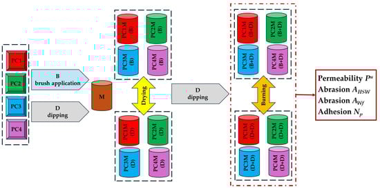
Figure 1.
Flowchart of the research programme.
3. Results
Permeability Pu, i.e., the ability to remove gases from the mould, is an important parameter of the moulding sand. The porous structure of the sand, which depends on the grain composition, quantity, and type of binder, creates different conditions for gas removal. Therefore, the structure of the compacted mass in the mould should be such that the conditions for the removal of these gases are met. Gas flow will be possible if there are appropriate channels in the mass, and these channels should be open on both sides. The theoretical basis for permeability in the measurement method used is based on phenomena related to the filtration of fluid through a porous medium. The permeability value is also affected by temperature. The influence of this factor is the most complex and difficult to characterise unambiguously. Under the influence of temperature, several phenomena occur in the moulding sand, which, depending on the composition of the moulding sand and its condition before pouring the liquid casting alloy (wet or dry sand), will affect permeability in different ways. Due to the influence of temperature and the dynamic impact of liquid metal on the mould cavity, protective coatings are applied to the surface of the moulding sand and core sand to protect them. On the one hand, this strengthens the top layer of the moulding sand, but at the same time, it reduces the permeability of the entire mould.
Table 5 presents the permeability results for cylindrical fittings with protective coatings applied in various ways. The results obtained were also compared with the permeability of the fittings without protective coatings.
Table 5.
Permeability Pu of moulding sand with protective coating.
The results obtained were subjected to statistical testing using a one-way analysis of variance (ANOVA). The analysis of the tested coatings was performed in two groups (B + D) and (D + D). The one-way analysis of variance showed statistically significant differences between the four groups: for coatings applied using the (B + D) method, the coefficient p = 0.041, and for (D + D), the coefficient p = 0.0305, which indicates that at least one group differs significantly from the others.
The results presented in Table 5 and Figure 2 indicate that the protective coatings used reduce the permeability of the compound to varying degrees. The PC4 protective coating had the highest permeability regardless of the application method. The least favourable results were found in the presented test for the protective coating marked PC3.
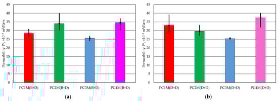
Figure 2.
Permeability Pu of moulding sand: (a) protective coating with brush application and dipping, (b) protective coating created using two-dipping process.
The dynamic impact on the protective coating was tested using abrasion tests. Two methods were used. The first abrasion test, AHSW, involved the impact of a steel shot thrown from a fixed height onto a rotating cylindrical fitting, which was protected by a protective coating on the side surface according to the procedure adopted in Table 4. In the second case, the cylindrical moulds were subjected to AWf abrasion on their entire side surface in contact with a cylindrical basket made in the form of a sieve.
As a result of the impact of the shot in the central part of the cylindrical moulding, the protective coating was abraded.
The results of the test are presented in Table 6. Figure 3 shows a graphical illustration of the results obtained. The test was also performed using this method for a fitting without coating as a reference sample.
Table 6.
Abrasiveness AHSW of the protective coating.
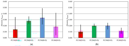
Figure 3.
Abrasiveness AHSW of the protective coating: (a) with brush application and dipping, (b) with two dips.
In the case of the one-way analysis of variance (ANOVA) performed on the data obtained for the AHSW abrasion, no significant differences were found between the analysis data groups. The coefficient p = 0.4565 was obtained for the application method (B + D), and the coefficient p = 0.1893 was obtained for the protective coating application method (D + D).
In the test, the lowest AHSW abrasion resistance was obtained for the PC1 coating, regardless of the application method. The worst results in this test were obtained for the PC3 coating. It is worth noting that the extreme abrasion results for the coatings using the AHSW method for the tested protective coatings show a twofold difference. At the same time, the double-immersion method was characterised by greater abrasion resistance for all protective coatings.
The next test was performed using a second method for testing abrasion. In this case, the frictional interaction refers to the entire side surface of the cylindrical fitting. The interaction is not point-like, but surface-like. The results of the AWf abrasion tests performed on the test apparatus are summarised in Table 7.
Table 7.
Abrasiveness AWf of the protective coating.
A one-way ANOVA variance analysis was also performed for this test. For this parameter, the coefficient p = 0.000001 for the protective coatings applied using the (B + D) method and p = 0.0085 for the (D + D) method. Since the values obtained are significantly lower than p < 0.05, the test indicates in both cases that at least two of the tested groups have mean values that differ significantly from each other.
A graphical illustration of the results obtained is presented in Figure 4.
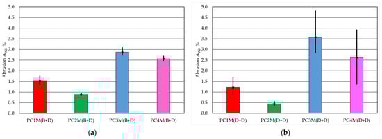
Figure 4.
Abrasiveness AWf of the protective coating: (a) with brush application and dipping, (b) with two dips.
The abrasion test carried out using the second method showed that the protective coating is the least susceptible to friction in contact with a moving steel screen, regardless of the method of application. It should be noted that two dips created a more resistant coating. The PC3 protective coating performed the worst in the test. The amount of protective coating that was worn out was several times greater than for the best PC2. This coating wore away more easily when applied via double-dipping.
A dedicated test for evaluating protective coatings applied to moulding sand is the Np adhesion test. In this method, the pressure at which damage occurs in the coating applied to a standardised cylindrical mould, subjected to compressed air blowing, is determined. Table 8 and Figure 5 show the results of the tests carried out. Figure 6, Figure 7, Figure 8 and Figure 9 show cylindrical moulding blocks after the destructive effect of pressure on the protective coatings applied in various ways.
Table 8.
Adhesion Np of the protective coating to the moulding sand.
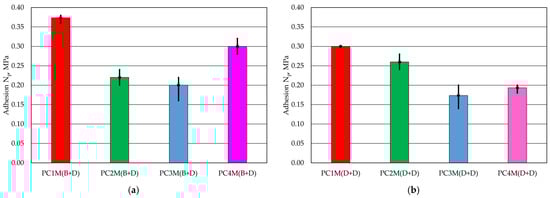
Figure 5.
Adhesion Np of the protective coating to the moulding sand: (a) with brush application and dipping, (b) with two dips.
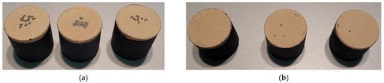
Figure 6.
Cylindrical fittings after adhesion Np test for PC1 protective coating applied using two methods: (a) PC1M (B + D), (b) PC1M (D + D).
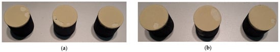
Figure 7.
Cylindrical fittings after adhesion Np test for PC2 protective coating applied using two methods: (a) PC2M (B + D), (b) PC2M (D + D).
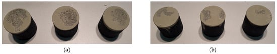
Figure 8.
Cylindrical fittings after adhesion Np test for PC3 protective coating applied using two methods: (a) PC3M (B + D), (b) PC3M (D + D).
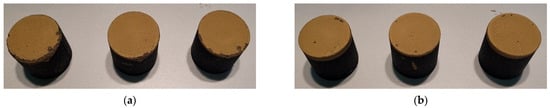
Figure 9.
Cylindrical fittings after adhesion Np test for PC4 protective coating applied using two methods: (a) PC4M (B + D), (b) PC4M (D + D).
A one-way ANOVA variance analysis was also performed for adhesion Np. For this parameter, the coefficient p = 0.000057 for the protective coatings applied using the (B + D) method, and p = 0.00013 for the (D + D) method. The values obtained are significantly lower than p < 0.05 in both cases, which means that at least two of the tested groups have mean values that differ significantly from each other.
The coating adhesion test showed that the PC1 protective coating applied via brush painting and dipping had the highest strength in the tests. In the case of the second application method, this coating also showed the best adhesive bond with the moulding sand sample. On the other hand, the PC3 coating was the weakest in the test for both coating application methods. It should also be noted that the protective coatings were damaged in different ways during this test. In the case of PC1 and PC4 coatings, the protective coating deteriorated in the form of localised damage to the surface of the moulding sand. The PC2 coating was damaged in the form of large flakes of protective coating that peeled off the top layer applied via dipping. The pressure had an even more destructive effect on the PC3 protective coating. As can be seen in Figure 8, both layers of the protective coating were damaged over a large area down to the moulding sand. It should be noted that the lower the strength of the protective coating, the greater its loss.
4. Discussion
The tests were conducted to determine which of the tested coatings could be recommended for industrial use as a protective coating for the moulding of chromite sand. The assessment was carried out by introducing a quality criterion for protective coatings for all four tests, assigning them the following weights: 1—worst result, 4—best result. Taking into account the adopted hierarchy, Table 9 summarises the parameter results of the tests for individual protective coatings, including their evaluation. The method of applying the protective coating was adopted as a distinguishing feature.
Table 9.
Classification of the technological properties of protective coatings applied to chromite moulding sand M.
Based on the tests conducted, it can be concluded that the best Pu permeability was obtained for the PC4 coating, regardless of the method of application of the two layers. Throughout the entire test, the permeability of the moulding sand Pu depended only on the protective coating used. However, it should be emphasised that protective coatings significantly reduce the permeability of the sand they protect. The appropriate relationship between the permeability of the cylindrical moulding sand with and without the protective coating, with the highest permeability Pu, is shown in Figure 10.
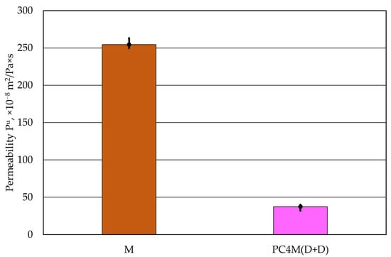
Figure 10.
Comparison of the permeability Pu of moulding sand with and without a protective coating.
The protective coating improves the quality of the casting surface by changing the surface of the moulding sand. Its application increases its resistance to temperature and the dynamic effects of liquid metal. As shown in Figure 11, it also significantly reduces an important parameter, namely, permeability, i.e., the ability to remove gases from the mould cavity.
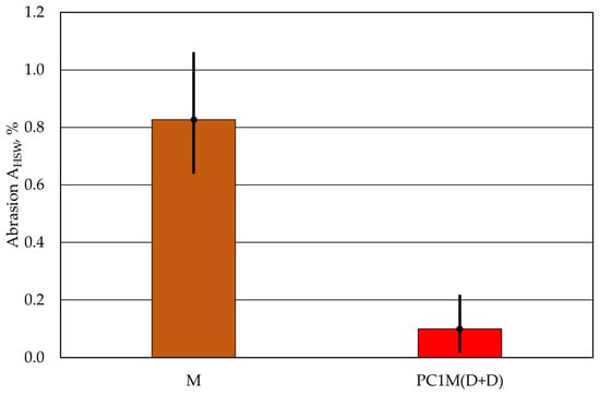
Figure 11.
Comparison of the abrasion AHSW of moulding sand with and without a protective coating.
The abrasion resistance of the protective coating applied to the surface of the moulding sand is another important parameter that affects the quality of the casting surface. In the case of the tests carried out, it was found that the protective coatings tested were destroyed in different ways as a result of dynamic interactions, depending on the test used. The method using a shot to impact the protective coating can be representative of a concentrated stream of liquid metal, which enters the mould cavity from the gating system and acts on the moulding sand at specific points. The second test, which refers to the entire surface of the moulding, can be interpreted as the effect of the rising level of liquid metal causing friction over a large area, filling the mould cavity and also causing abrasion. In foundry work, the abrasiveness of the moulding sand is determined by the fact that the grains of the matrix on the surface of the mould cavity or core are subject to conditions different from those of the grains inside the moulding sand. The latter are surrounded on all sides by neighbouring grains, while the former are only bound to the moulding sand from the inside, and their outer part reproduces the surface of the mould cavity and core. Therefore, the strength of the outer layer of the moulding sand is lower than the average strength of the sand [37]. This is why the use of protective coatings is so important.
The tests carried out showed different abrasion resistance of protective coatings, depending on the test method used, which is an approximate equivalent of the dynamic interactions occurring in the mould cavity. The PC1 protective coating proved to be more resistant to the impact of a concentrated stream of material on its surface, regardless of the method of application. The PC3 protective coating performed the worst in this test, regardless of the method of application to the surface of the cylindrical moulding. However, it is important to emphasise the extent to which the protective coating increases the strength of the upper layer of the moulding sand. According to the data in Table 6, regardless of the type of protective coating and the method of application to the AHSW moulding sand, the abrasion resistance of the tested samples is several times lower than that of the initial cylindrical mould without a coating. Figure 11 compares the abrasion result obtained for the uncoated cylindrical moulding with the moulding with the protective coating with the best result, i.e., the smallest loss.
Simultaneous mechanical impact across the entire surface of the sample was best tolerated by coatings PC2 and PC1, while the protective coating PC3 again proved to be the weakest. In this test, too, the method of applying the protective coating did not affect the numerical value of the evaluation criterion.
In the case of determining the adhesion Np of the protective coating, marked by the pressure value at which the coating breaks, the best result was obtained for the PC1 coating, and the worst result was again marked for the PC3 coating, in the case of moulding sand on a given chromite matrix and the binder used. Furthermore, a visual analysis of the protective coatings obtained was performed on cross-sections of specially prepared longitudinal samples. Examples of the images recorded are shown in Figure 12.
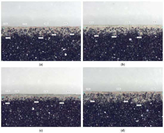
Figure 12.
Cross-section view of protective coatings formed on the surface of the moulding sand M using the (D + D) method, with ×5 magnification: (a) PC1; (b) PC2; (c) PC3; (d) PC4.
Despite the same application procedure for all protective coatings, different thicknesses were obtained. This applies to both the top layer and the layer formed by the penetration of the protective coating into the porous structure of the moulding sand during immersion. The prepared images of the protective coating layers may justify the results obtained for the parameters tested.
The PC1 protective coating was characterised by the lowest abrasion. This result may have been influenced by the thinnest layer on top of the protective coating (Figure 12a). The thin layer of protective coating limited the possibility of producing a large amount of abrasion products. At the same time, the PC1 coating had the highest adhesion, which can also be attributed to the thinnest top layer. The protective coating was compact, influencing the specific manner of its destruction. The protective coating layer broke at specific points (Figure 6), causing damage across its entire thickness. At the same time, the thin but compact top layer and significant penetration into the moulding sand structure limited its permeability.
The PC3 protective coating performed the worst in all tests. Analysis of the cross-section of the sample with this protective coating (Figure 12c) shows a limited ability to penetrate the moulding sand. At the same time, the thickness of the top layer is the greatest, as illustrated by the measurements taken. The significant thickness of the protective coating measured limits permeability and, in abrasion tests, contributed to the formation of the largest amount of abrasion products. The limited penetration of the PC3 protective coating into the porous structure of the moulding sand, i.e., its poor bonding with the substrate, meant that it was most easily damaged in adhesion tests. As can be seen in Figure 8, the lack of adequate bonding to the substrate caused large fragments of this protective coating to detach at the lowest pressure.
The use of the same application procedures resulted in the creation of different coating thicknesses, depending on the protective coating. During the application, the same viscosity of the protective coatings was used, determined on the basis of a test performed with a Ford cup. The viscosity of the protective coating is an important parameter from a technological point of view. However, the amount of isopropyl alcohol added to obtain this technological parameter could determine the thickness of the layers after its evaporation or burning.
5. Conclusions
The tests were conducted to identify a suitable protective coating for use by a foundry using chromite grain matrix to cast manganese steel. During the tests, identical test conditions were created for all protective coatings tested. In production plants, much depends on the technological regime, weather conditions, and staff. Unfortunately, this aspect is beyond the scope of laboratory analyses and is only a premise, a direction for how to implement a given process. By analysing all the results of the properties of the tested protective coatings, it is difficult to clearly determine the impact of the application method on the obtained values of the tested parameters. In most cases, the criteria values did not indicate a dominant influence of the method of coating application and drying on its suitability. However, a summary of the assigned criterion values of individual tests in the field of evaluation indicates that the PC1 protective coating obtained the highest value from those indicated for use by individual suppliers for application in chromite moulding sand and manganese steel casting. This indication does not take into account other important factors that are within the control of the foundry. These include coating costs, production efficiency, ease of use, and safety, taking into account production profitability, internal conditions, and safety regulations in force at the company. Environmental considerations suggest the use of water-based protective coatings. However, because of production efficiency and cost (drying or burning speed), protective coatings with alcohol as a thinner are more desirable.
However, several factors that may influence the result obtained should be pointed out:
- The thickness of the top layer of the protective coating;
- The depth of penetration of the protective coating into the moulding sand;
- The chemical composition and size of the solid particles forming the protective coating;
- The degree of dilution of the protective coating to obtain a specific viscosity.
Since the protective coatings used for the tests, whose chemical composition and particle size are the “know-how” of the manufacturer, the most suitable protective coating was only determined by technological tests.
To summarise the tests carried out, it should be emphasised that protective coatings protect the top layer of the mould against dynamic effects (greater abrasion resistance). They create a stronger and smoother top layer, which improves the surface of the castings. However, existing protective coating solutions based on fine fractions of refractory materials cause a deterioration in a very important mass parameter, namely, permeability. Therefore, it seems that solutions should be sought that improve some quality parameters without deteriorating others.
Author Contributions
Methodology, M.Ł. and D.D.; validation, M.Ł., D.D., A.P., and P.F.; formal analysis, M.Ł. and D.D.; investigation, M.Ł. and D.D.; writing—original draft preparation, M.Ł. and D.D.; writing—review and editing, M.Ł.; visualisation, D.D., A.P., and P.F.; supervision, M.Ł.; funding acquisition, M.Ł. All authors have read and agreed to the published version of the manuscript.
Funding
This research was funded by the Polish Ministry of Science and Higher Education (grant number 16.16.170.7998/B507) and the Slovak Ministry of Education SR (grant number “VEGA 1/0001/25”).
Institutional Review Board Statement
Not applicable.
Informed Consent Statement
Not applicable.
Data Availability Statement
Data is contained within the article.
Conflicts of Interest
The authors declare no conflicts of interest.
References
- Aramide, B.; Pityana, S.; Jamiru, T.; Popoola, P.; Sadiku, R. Influence of Vanadium-Chromium Carbide on the Microstructure of Reinforced FeCrV15 Hardfacing during Laser Cladding Deposit. J. Mater. Eng. Perform. 2022, 31, 514–523. [Google Scholar] [CrossRef]
- Monção, F.C.; Caliari, F.R.; Freitas, F.E.; Couto, A.A.; Augusto, A.; Lima, C.R.C.; Massi, M. Wear Resistance Evaluation of Self-Fluxing Nickel-Based Coating Deposited on AISI 4340 Steel by Atmospheric Plasma Spray. Metals 2024, 14, 532. [Google Scholar] [CrossRef]
- Korobov, Y.; Antonov, M.; Astafiev, V.; Brodova, I.; Kutaev, V.; Estemirova, S.; Devyatyarov, M.; Okulov, A. Erosion Wear Behavior of HVAF-Sprayed WC/Cr3C2-Based Cermet and Martensitic Stainless Steel Coatings on AlSi7Mg0.3 Alloy: A Comparative Study. J. Manuf. Mater. Process. 2024, 8, 231. [Google Scholar] [CrossRef]
- Gao, Y.; Bai, S.; Kou, G.; Jiang, S.; Liu, Y.; Zhang, D. Microstructure Characteristics and Elevated-Temperature Wear Mechanism of FeCoCrNiAl High-Entropy Alloy Prepared by Laser Cladding. Processes 2024, 12, 2228. [Google Scholar] [CrossRef]
- Bi, Z.; Li, T. Microstructure and Wear Resistance of FeCrV15 Coatings by Laser Cladding. Metals 2024, 14, 1136. [Google Scholar] [CrossRef]
- Wang, S.; Song, W.; An, L.; Xia, Z.; Zhang, S. Fabrication and Tribology Properties of PTFE-Coated Cemented Carbide Under Dry Friction Conditions. Lubricants 2024, 12, 363. [Google Scholar] [CrossRef]
- Bartkowski, D.; Bartkowska, A. Wear Resistance in the Soil of Stellite-6/WC Coatings Produced Using Laser Cladding Method. Int. J. Refract. Metals Hard Mater. 2017, 64, 20–26. [Google Scholar] [CrossRef]
- Ma, S.; Zhang, C.; Li, L.; Chen, H.; Yang, Y. Effects of Tungsten Addition on the Microstructure and Properties of FeCoCrNiAl High-Entropy Alloy Coatings Fabricated via Laser Cladding. Materials 2024, 17, 3592. [Google Scholar] [CrossRef]
- Lu, J.Z.; Cao, J.; Lu, H.F.; Zhang, L.Y.; Luo, K.Y. Wear Properties and Microstructural Analyses of Fe-Based Coatings with Various WC Contents on H13 Die Steel by Laser Cladding. Surf. Coat. Technol. 2019, 369, 228–237. [Google Scholar] [CrossRef]
- Saternus, M.; Kania, H. Effect of Mg on the Formation of Periodic Layered Structure during Double Batch Hot Dip Process in Zn-Al Bath. Materials 2021, 14, 1259. [Google Scholar] [CrossRef]
- Bracka-Kęsek, K.; Szczęsny, A.; Guzik, E.; Kopyciński, D. Evaluation of Effect of Ti Addition to Zinc Bath on Kinetics of Growth of Alloy Layer Formed in Process of Hot-Dip Galvanisation on Steel Substrate. Materials 2023, 16, 4773. [Google Scholar] [CrossRef]
- Marek, A.; Steinerová, V.; Pokorný, P.; Kania, H.; Berger, F. High-Temperature Zn-5Al Hot Dip Galvanizing of Reinforcement Steel. Coatings 2024, 14, 959. [Google Scholar] [CrossRef]
- Skotnicki, W.; Jędrzejczyk, D. Comparative Analysis of Coatings Applied for Anti-Corrosion Protection of Public Transport Vehicles’ Structural Parts. Materials 2024, 17, 3763. [Google Scholar] [CrossRef]
- Cole, I.S. Recent Progress and Required Developments in Atmospheric Corrosion of Galvanised Steel and Zinc. Materials 2017, 10, 1288. [Google Scholar] [CrossRef]
- Pokorný, P.; Chobotský, T.; Prodanovic, N.; Steinerová, V.; Hurtig, K. Bond Strength and Corrosion Protection Properties of Hot-Dip Galvanized Prestressing Reinforcement in Normal-Strength Concrete. J. Compos. Sci. 2024, 8, 407. [Google Scholar] [CrossRef]
- Luo, X.; Lu, H.; Zhong, Y.; Ren, W.; Lei, Z. Study of Flow and Zinc Dross Removal in Hot-Dip Galvanizing with Combined Traveling Magnetic Field. Materials 2024, 17, 4799. [Google Scholar] [CrossRef]
- Vontorová, J.; Novák, V.; Váňová, P. Low-Carbon Steel Formed by DRECE Method with Hot-Dip Zinc Galvanizing and Potentiodynamic Polarization Tests to Study Its Corrosion Behavior. Metals 2024, 14, 993. [Google Scholar] [CrossRef]
- Liu, Q.; Cao, Y.; Chen, S.; Xu, X.; Yao, M.; Fang, J.; Lei, K.; Liu, G. Hot-Dip Galvanizing Process and the Influence of Metallic Elements on Composite Coatings. J. Compos. Sci. 2024, 8, 160. [Google Scholar] [CrossRef]
- Kania, H. Structure and Corrosion Resistance of Coatings Obtained by the Batch Double Hot Dip Method in Eutectoid ZnAl Bath with the Addition of Mg and Si. Coatings 2022, 12, 1207. [Google Scholar] [CrossRef]
- Vontorová, J.; Mohyla, P.; Kreislová, K. Quality of Zinc Coating Formed on Structural Steel by Hot-Dip Galvanizing after Surface Contamination. Coatings 2024, 14, 493. [Google Scholar] [CrossRef]
- Pinger, T.; Brand, M.; Grothe, S.; Marginean, G. Abrasive Wear Behavior of Batch Hot-Dip Galvanized Coatings. Materials 2024, 17, 1547. [Google Scholar] [CrossRef] [PubMed]
- Comparini, A.; Del Pace, I.; Giurlani, W.; Emanuele, R.; Verrucchi, M.; Bonechi, M.; Innocenti, M. Electroplating on Al6082 Aluminium: A New Green and Sustainable Approach. Coatings 2023, 13, 13. [Google Scholar] [CrossRef]
- Grzejda, R.; Kobielarz, M. Testing the Mechanical Properties of High-Strength Zinc-Coated Bolts: FEM Approach. Coatings 2023, 13, 27. [Google Scholar] [CrossRef]
- Dubiel, T.; Grzejda, R. Effect of Atmospheric Conditions on the Tightening Behaviour of HV Galvanised Bolts in Structural Bolt Sets. Lubricants 2023, 11, 460. [Google Scholar] [CrossRef]
- Melo, R.H.R.Q.; Falcão, J.R.; Bersch, J.D.; Baptista, D.T.; Masuero, A.B. Performance and Durability of Paints for the Conservation of Historic Façades. Buildings 2024, 14, 1016. [Google Scholar] [CrossRef]
- Calovi, M.; Rossi, S. Assessing the Impact of Sepiolite-Based Bio-Pigment Infused with Indigo Extract on Appearance and Durability of Water-Based White Primer. Materials 2024, 17, 941. [Google Scholar] [CrossRef]
- Cui, G.; Bi, Z.; Zhang, R.; Liu, J.; Yu, X.; Li, Z. A Comprehensive Review on Graphene-Based Anti-Corrosive Coatings. Chem. Eng. J. 2019, 373, 104–121. [Google Scholar] [CrossRef]
- Wang, Y.; Hsu, C.; Pan, G.; Chen, C. Application of Self-Polishing Copolymer and Tin-Free Nanotechnology Paint for Ships. J. Mar. Sci. Eng. 2024, 12, 1662. [Google Scholar] [CrossRef]
- Nurlybayev, R.E.; Kuldeyev, E.I.; Altayeva, Z.N.; Zhumadilova, Z.O.; Yestemessova, A.S.; Orynbekov, Y.S. Study of Properties of Water-Dispersion Paint and Varnish Compositions with the Content of Modified Mineral Filler. Coatings 2024, 14, 1154. [Google Scholar] [CrossRef]
- Yang, S.; Zhu, S.; Hong, R. Graphene Oxide/Polyaniline Nanocomposites Used in Anticorrosive Coatings for Environmental Protection. Coatings 2020, 10, 1215. [Google Scholar] [CrossRef]
- Liu, X.; Gao, Z.; Wang, D.; Yu, F.; Du, B.; Gitsov, I. Improving the Protection Performance of Waterborne Coatings with a Corrosion Inhibitor Encapsulated in Polyaniline-Modified Halloysite Nanotubes. Coatings 2023, 13, 1677. [Google Scholar] [CrossRef]
- Sørensen, P.A.; Kiil, S.; Dam-Johansen, K.; Weinell, C.E. Anticorrosive Coatings: A Review. J. Coat. Technol. Res. 2009, 6, 135–176. [Google Scholar] [CrossRef]
- Almoiqli, M.; Alharbi, K.N.; Alnuwaiser, M.A.; Yajizi, G.; Alshoshan, S.; Baduways, W.; Albeladi, M.I.; Alsanea, R.S.; Aljohani, T.A. Corrosion Behavior of Aluminium-Coated Cans. Materials 2023, 16, 1041. [Google Scholar] [CrossRef] [PubMed]
- Łucarz, M.; Jędrychowski, M. Method of Stamping the Progression of a Beverage End Rivet of a Thinner Sheet of AW-5182 Alloy. Materials 2023, 16, 6244. [Google Scholar] [CrossRef]
- Alonso-Jiménez, A.; Alonso, P.M.; Hormaza-Polo, E. Sustainable Fire Protection: Reducing Carbon Footprint with Advanced Coating Technologies. Appl. Sci. 2024, 14, 7826. [Google Scholar] [CrossRef]
- Caratenuto, A.; Leung, S.; LeCompte, N.; Zheng, Y. Size-Dispersed Calcium Phosphate-Based Paints for Sustainable, Durable Cool Roof Applications. Energies 2024, 17, 4178. [Google Scholar] [CrossRef]
- Lewandowski, J.L. Casting Mould Materials; Akapit Publishing House: Krakow, Poland, 1997. (In Polish) [Google Scholar]
- Holtzer, M.; Bobrowski, A.; Drożyński, D.; Mocek, J. Investigations of protective coatings for castings of high-manganese cast steels. Arch. Foundry Eng. 2013, 13, 39–44. [Google Scholar] [CrossRef]
- Jamrozowicz, Ł.; Zych, J.; Kolczyk, J. The Drying Kinetics of Protective Coatings Used on Sand Molds. Metallurgy 2014, 54, 23–26. [Google Scholar]
- Jamrozowicz, Ł.; Zych, J.; Snopkiewicz, T. The Research of Desiccation Rates Selected Protective Coating Used on Mould and Sand Cores. Arch. Foundry Eng. 2013, 13, 45–50. [Google Scholar]
- Jamrozowicz, Ł.; Siatko, A. The Assessment of the Permeability of Selected Protective Coatings Used for Sand Moulds and Cores. Arch. Foundry Eng. 2020, 1, 17–22. [Google Scholar] [CrossRef]
- Jamrozowicz, Ł.; Kolczyk-Tylka, J.; Siatko, A. Investigations of the thickness of protective coatings deposited on moulds and cores. Arch. Foundry Eng. 2018, 18, 131–136. [Google Scholar] [CrossRef]
- Holtzer, M.; Bobrowski, A.; Drożyński, D.; Mocek, J. Selection of Protective Coatings of Moulds for Castings of High-Manganese Cast Steel in Dependence of The Applied Moulding Sand Kind. Arch. Metall. Mater. 2013, 58, 853–857. [Google Scholar] [CrossRef]
- Milanova, G. Foundry Coatings: Review. J. Mater. Eng. 2023, 1, 45–53. [Google Scholar] [CrossRef]
- López-Ortega, A.; Areitioaurtena, O.; Fuentes, E.; Igartua, A.; Merchán, L.; Pardo, E.; Montero, J.; Granado, R.; Martinez de la Pera, I.; Mendizabal, J.; et al. Experimental Evaluation of Ceramic Coatings for Die Protection in Low-Pressure Die-Casting Process. Coatings 2024, 14, 643. [Google Scholar] [CrossRef]
- Coatings for Moulds and Cores. In Foseco Ferrous Foundryman’s Handbook; Elsevier: Amsterdam, The Netherlands, 2000; pp. 226–244.
- Sertucha, J.; Lacaze, J. Casting Defects in Sand-Mold Cast Irons—An Illustrated Review with Emphasis on Spheroidal Graphite Cast Irons. Metals 2022, 12, 504. [Google Scholar] [CrossRef]
- Nwaogu, U.C.; Tiedje, N.S. Foundry Coating Technology: A Review. Mater. Sci. Appl. 2011, 2, 1143–1160. [Google Scholar] [CrossRef]
- Holtzer, M.; Kmita, A. Protective Coatings for Mold and Core Sands. In Mold and Core Sands in Metalcasting: Chemistry and Ecology; Springer: Cham, Switzerland, 2020; pp. 285–293. [Google Scholar]
- Kmita, A.; Zych, J.; Holtzer, M.; Mocek, J.; Piasny, S. Ecological Water-Based Protective Coatings for Moulds and Cores of Iron Castings. Metalurgija 2016, 55, 589–592. [Google Scholar]
- Romelczyk, R.; Przyszlak, N.; Siodmok, B.; Dorula, J.; Studnicki, A. The Influence of Selected Water and Alcohol Based Coatings on Bending Strength of Foundry Moulds and Cores Manufactured in Furan Technology. Arch. Foundry Eng. 2018, 18, 169–172. [Google Scholar]
- Jamrozowicz, Ł.; Zych, J. Humidity Migration in Surface Layers of Sand Moulds During Processes of Penetration and Drying of Protective Coatings. Arch. Foundry Eng. 2022, 22, 72–78. [Google Scholar] [CrossRef]
- Mocek, J. Gaseous Atmosphere during Gas Forming Tendency Measurements of the Selected Protective Coatings for Sand Moulds. Arch. Foundry Eng. 2021, 21, 11–18. [Google Scholar] [CrossRef]
- Anwar, N.; Sappinen, T.; Jalava, K.; Orkas, J. Comparative Experimental Study of Sand and Binder for Flowability and Casting Mold Quality. Adv. Powder Technol. 2021, 32, 1902–1910. [Google Scholar] [CrossRef]
- Břuska, M.; Beňo, J.; Cagala, M.; Jasinková, V. Dilatometric characterization of foundry sands. Arch. Foundry Eng. 2012, 12, 9–14. [Google Scholar] [CrossRef]
- Horton, K.B.; Joyce, S.; Gilson, D.M. Sand Distribution: A Study of It’s Effects on Core Strength and Casting Quality. In Proceedings of the Transactions of the American Foundrymen’s Society and the Proceedings of the One Hundred First Annual Meeting: American Foundrymen’s Society/Casting Congress, Seattle, WA, USA, 20–23 April 1997; pp. 1–12. [Google Scholar]
- Łucarz, M.; Drożyński, D.; Kaczmarska, K.; Pribulová, A.; Futáš, P. Influence of the Applied Protective Coating on the Technological Parameters of the Moulding or Core Sand Surface. Materials 2024, 17, 5737. [Google Scholar] [CrossRef] [PubMed]
- BN-80/4024-04; Odlewnicze Materiały Formierskie–Pokrycia Ochronne Do Form i Rdzeni–Technologiczna Próba Przyczepności. Wydawnictwa Normalizacyjne: Warszawa, Poland, 1981.
- BN-77/4024-02; Odlewnicze Masy Formierskie i Rdzeniowe–Badanie Osypliwości. Wydawnictwa Normalizacyjne ALFA: Warszawa, Poland, 1977.
- Polish Committee for Standardization. Foundry Moulding Materials—Strength Measurement; Technical Report PN-83/H-11073:1983; Polish Committee for Standardization: Warszawa, Poland, 1983. [Google Scholar]
Disclaimer/Publisher’s Note: The statements, opinions and data contained in all publications are solely those of the individual author(s) and contributor(s) and not of MDPI and/or the editor(s). MDPI and/or the editor(s) disclaim responsibility for any injury to people or property resulting from any ideas, methods, instructions or products referred to in the content. |
© 2025 by the authors. Licensee MDPI, Basel, Switzerland. This article is an open access article distributed under the terms and conditions of the Creative Commons Attribution (CC BY) license.