Abstract
This study investigates the effect of cathodic voltage on the thickness, morphology, composition, phase structure, adhesion, and elevated-temperature oxidation resistance of the micro-arc oxidation (MAO) ceramic coatings on Ti65 alloy. Coatings were fabricated via MAO under cathodic voltages of 50 V, 100 V, 150 V, and 200 V. Results indicate that the coatings primarily consist of rutile TiO2 (R-TiO2), anatase TiO2 (A-TiO2), and amorphous SiO2. The thickness of the MAO coatings increased with rising cathodic voltage, while the surface porosity and average pore size of the coatings were first decreased and then increased with the increase in cathodic voltage. Excellent coating adhesion to the substrate was confirmed by 50 thermal shock cycles between 700 °C and room temperature. Cyclic oxidation tests at 750 °C for 100 h demonstrated that all MAO coatings significantly enhanced elevated-temperature oxidation resistance compared to the bare Ti65 substrate. Notably, the coating produced at 100 V exhibited the lowest oxidation weight gain (0.50 mg/cm2), amounting to only one-third of the substrate’s gain. The effect of the cathodic voltage on the high-temperature oxidation performance of the MAO coatings was systematically analyzed.
1. Introduction
Titanium alloys have found extensive applications in the aerospace [1], navigation [2], petroleum [3], and biomedical [4] fields owing to their low density [5], high specific strength [6], excellent corrosion resistance [7], and superior biocompatibility [8]. As a widely utilized structural material, the application proportion of titanium alloys in civil aircraft has been progressively increasing on an annual basis, establishing it as a critical strategic material in aviation [9,10,11]. However, titanium alloys are prone to reacting with oxygen under high-temperature aerobic conditions [12,13,14]. This results in the formation of a loose, brittle oxide layer easy to peel from the substrate surface and fails to provide adequate protection for the substrate. Consequently, the oxidation behavior significantly impairs the service performance of titanium alloys and reduces their service life [15,16].
In recent years, two primary approaches have been employed to enhance the high-temperature oxidation resistance of titanium alloys: alloying and preparation of protective coatings. Studies have demonstrated that the primary alloying elements enhancing the high-temperature oxidation resistance of titanium alloys include Al [17], Ta [18], Si [19], W [20], Cr [21], Mo [22], Nb [23], B, and Y [24]. A continuous, dense, and well-adhered oxide film is formed on the titanium alloy at high temperatures by optimizing the composition of titanium alloys, thereby enhancing their high-temperature oxidation resistance. Nevertheless, the effectiveness of the alloying method in enhancing the high-temperature oxidation resistance of titanium alloys has been limited. Since the 1950s, the maximum service temperature of titanium alloys has increased by 70 °C every decade. 600 °C has nearly become the upper limit of temperature that titanium alloys can withstand in an ambient air environment for long-cycle service due to various constraints [25].
Applying protective coating is one of the most effective methods to enhance the high-temperature oxidation resistance of titanium alloys. Commonly employed coating application techniques encompass physical vapor deposition [26,27,28], chemical vapor deposition [29,30], laser cladding [31], sol-gel process [32], plasma spraying [33,34,35], magnetron sputtering [36], multi-arc ion plating [37], and micro-arc oxidation (MAO) [38,39].
The Ti65 alloy was developed as a nearly α-type titanium alloy to serve as a high-temperature structural material at 600–650 °C for aero-engine applications [40,41]. Although Ti65 exhibits excellent high-temperature performance, it inevitably undergoes surface oxidation when operating temperatures exceed 650 °C. A phosphate–ceramic coating was developed for high-temperature oxidation protection of Ti65 using air spraying technology [42]. This coating demonstrated excellent thermal shock resistance and elevated oxidation resistance, with a minimal weight gain of 0.35 mg/cm2 at 650 °C. A novel Cr2AlC coating was fabricated on Ti65 alloy by magnetron sputtering [43]. Isothermal oxidation tests were performed at 650 and 750 °C for up to 400 h in air. Compared to the bare Ti65 substrate, the coated samples revealed more excellent oxidation resistance, meeting the parabolic law with low oxidation rate constants, which is attributed to Al preferentially oxidizing to form the protective Al2O3 layer and synchronously Cr7C3 sublayer, retarding the inward diffusion of oxygen. Cr-added Ti-Al-Si composite coatings were prepared using a two-step hot-dipping + pre-oxidation method on Ti65 alloy [41]. All samples were weighed every 48 h until the high-temperature oxidation experiment was stopped at 480 h. The results show that Cr-added Ti-Al-Si composite coatings could significantly improve the high-temperature oxidation resistance of Ti65 alloy, which was mainly due to the Cr segregated on the Ti(Al,Si,Cr)3 phase boundary (the main path of oxidation), and promoted the selective oxidation of Al to form Al2O3.
Among surface treatment methods, the MAO technology has gained significant attention due to its avoidance of expensive production equipment and operational simplicity [39,44]. During this process, high voltage is applied in an electrolyte solution containing specific ions, generating micro-arc discharges. These discharges facilitate the electrolysis of water in the solution, producing oxygen. This oxygen enables the in situ formation of a ceramic coating on the metal surface that exhibits exceptional properties, including wear resistance, corrosion resistance, and high-temperature oxidation resistance. Consequently, the application of MAO technology to improve the high-temperature oxidation resistance of titanium alloys has become a prominent research focus in recent years [45,46].
The microstructure and properties of the oxide layer formed as a result of MAO depend on various factors, such as matrix composition, electrolyte composition, power supply mode, electrical parameters, oxidation time, etc. [47]. It has been reported that the bipolar current pulse mode produces thicker and more uniform coatings compared to the unipolar current pulse mode [48]. Li [49] investigated the effect of cathodic voltage on the growth rate and wear resistance of MAO coating fabricated on 2024 aluminum alloys. When the applied cathodic voltage increased, the coatings exhibited a more compact structure, and the coating growth rate significantly increased with increasing the applied cathodic voltage. The alumina content in the coatings increased while the silicate oxides decreased with the increase in cathodic voltage. As a result, the wear resistance of the PEO coatings significantly improved with the increase in cathodic voltage. By varying the cathodic voltage (0–30 V), Liu [50] prepared a MAO coating with Al2O3 as the main crystal phase on the surface of the NiTi alloy. The thickness and surface roughness of the MAO coatings increased with increasing cathodic voltage. The corrosion resistance of the coated NiTi decreases with increasing cathodic voltage. Based on the aforementioned research, a definitive conclusion regarding the influence of cathodic voltage on the microstructure and properties of MAO coatings has not yet been established. Furthermore, studies focusing on titanium alloys remain relatively limited.
In this study, ceramic coatings were fabricated on Ti65 alloy using the micro-arc oxidation (MAO) technique. The main purpose of this work is to systematically research the effect of cathodic voltage on the phase composition, microstructure, and elevated-temperature oxidation performance of the MAO coatings on Ti65 alloy.
2. Materials and Methods
2.1. Materials and Coating Preparation Process
The substrate material used in this study was Ti65 alloy sheet with a nominal composition of Ti-5.9Al-4.0Sn-3.5Zr-0.3Mo-0.4Si-0.3Nb-2.0Ta-1.0W-0.05C (wt.%). The alloy was cut into specimens with dimensions of 15 mm × 10 mm × 1.5 mm using wire electrical discharge machining. A circular hole of 3 mm diameter was drilled near the middle of one end of the sample for the purpose of facilitating sample suspension. The surfaces of the specimens were sequentially polished using SiC sandpapers of 320#, 600#, 800#, and 1000#. All edges of the specimens were chamfered to minimize stress concentrations caused by edge discharges during MAO. The specimens were then washed with water, ultrasonically cleaned in anhydrous ethanol, and dried with cold air.
The MAO process was carried out using an adjustable dual-pulse power supply (S0YI-500-10DMT, Shanghai Soyi Electronics Co., Ltd., Shanghai, China). Table 1 details the electrical parameters of various MAO samples, which are labeled as MAO-50, MAO-100, MAO-150, and MAO-200, prepared under the cathodic voltages of 50 V, 100 V, 150 V, and 200 V, respectively. The electrolyte used for the MAO process consisted of 30 g/L Na2SiO3, 10 g/L (NaPO3)6, 2 g/L Na2MoO4, 2 g/L KOH, and deionized water. A water-cooling system was used to maintain the electrolyte temperature below 40 °C, and mechanical stirring at 180 r/min was adopted to ensure the homogeneity of the solution. After MAO, the samples were rinsed with deionized water, ultrasonically cleaned in anhydrous ethanol, and dried with cold air.

Table 1.
Electrical parameters of the various MAO samples.
2.2. Coating Characterization
The surface morphology of the coatings was observed using a Zeiss Ultra Plus field emission scanning electron microscope (Jena, Germany) equipped with energy dispersive spectroscopy (EDS). Phase composition of the coatings was analyzed by X-ray diffraction (XRD) using a Rigaku SmartLab system (Tokyo, Japan) at a scan rate of 2°/min over a 2θ range of 10°~90°. The chemical states of the elements in the coatings were examined using X-ray photoelectron spectroscopy (XPS, Thermo Fisher ESCALAB Xi+, Thermo Fisher Scientific Inc, Waltham, MA, USA).
2.3. Thermal Shock Tests of the Coatings
The coated samples were subjected to thermal shock testing in a resistance furnace (model SX2-6-13, Jinan Olabo Scientific Instrument Co., Ltd., Jinan, China). Samples were heated to 700 °C and held for 5 min before being immersed in water at 25 °C for cooling. This cycle was repeated 50 times. Surface state of the samples was observed after each cycle, and the weight of the samples was recorded after every five cycles.
2.4. High Temperature Oxidation Tests of the Coating Samples
Ti65 substrate and coated samples were placed in ceramic crucibles and subjected to cyclic oxidation testing in a resistance furnace (model SX2-6-13) at 750 °C. Each cycle involved 10 h of oxidation followed by cooling to room temperature. The weight change of the samples was recorded after each cycle using an analytical balance. This process was repeated for 10 cycles, resulting in a total oxidation time of 100 h.
3. Results and Discussion
3.1. Coating Microstructure Characteristics
3.1.1. Surface Morphologies and EDS Analyses of the MAO Coatings
Figure 1 shows the surface morphology of the MAO coatings. Figure 1a,d,g,j display the low-magnification surface morphology of MAO-50, MAO-100, MAO-150, and MAO-200 coatings, respectively. Figure 1b,e,h,k show the high-magnification surface morphology of the four coatings, while Figure 1c,f,i,l present the corresponding EDS spectra of the surface composition. From the images, it can be observed that the MAO coatings exhibit a three-dimensional porous network structure, consisting of a porous surface and “volcanic-like” top pores. The pores in the coatings are formed by oxygen gas bubbles and molten oxide particles that are expelled from the channels during the coating growth process. When the cathodic voltage was 50 V, the coating showed a slow growth rate due to the low working voltage, resulting in uneven film growth with a rough surface. When the cathodic voltage was 100 V, the surface of the coating exhibited a relatively smooth texture with uniformly sized pores. As the cathodic voltage increased, the MAO-150 coating surface exhibited local bulging and protrusions, and the pore sizes became more varied, with an overall increasing trend. When the cathodic voltage increased to 200 V, the coating surface became very rough, with many bulges and irregularly sized pores.
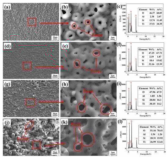
Figure 1.
SEM surface morphologies and EDS elements composition of various MAO coatings: (a–c) MAO-50, (d–f) MAO-100, (g–i) MAO-150, and (j–l) MAO-200.
Table 2 shows the average pore size and surface porosity of various MAO coatings prepared under different cathodic voltages. When the cathodic voltage was relatively low, the formation of MAO coatings with micro-sized pores was more likely to occur. Compared with the MAO-50 coating, the MAO-100 coating exhibited a comparable level of surface porosity; however, it featured the smallest pore size. When the cathodic voltage exceeded 100 V, an increase in the cathodic voltage resulted in a corresponding increase in both the pore size and porosity of the MAO coating surface.
Table 2.
Average pore size and surface porosity of various MAO coatings.
As the cathodic voltage increased, the current through the sample surface increased, which led to the generation of higher-energy electrical sparks and the formation of wider pores on the coating surface. From the EDS spectra in Figure 1c,f,i,l, it can be seen that all coatings are enriched with O, Si, and Ti elements, as well as a minor portion of Al. The Ti peak of the MAO-50 coating is the strongest compared with the other three coatings, possibly due to the thinner coating allowing more signals from the underlying Ti65 alloy substrate to be detected. The O element originates from the H2O in the electrolyte, which generates O2 during the MAO process, while the Si in the coatings primarily comes from Na2SiO3 in the electrolyte because of the very low Si content of the Ti65 alloy.
3.1.2. Cross-Sectional Morphologies and EDS Analyses of the MAO Coatings
Figure 2 shows the cross-sectional morphologies of various MAO coatings. Figure 2a–d correspond to the cross-sectional views of MAO-50, MAO-100, MAO-150, and MAO-200 coatings, respectively. The interface between the MAO coatings and the substrate is clearly visible, and the continuity of the coating remains intact, indicating strong adhesion between the coating and the substrate. The average thickness of the MAO-50 coating is approximately 0.99 μm, whereas for MAO-100, it is about 2.58 μm; for MAO-150, it is approximately 3.62 μm; and for MAO-200, it is approximately 19.34 μm. This shows that with increasing cathodic voltage, the micro-arc discharge reaction becomes more intense, accelerating the coating growth rate, leading to more surface protrusions and depressions, and increasing roughness. Various-sized pores are clearly visible in the cross-sectional view, and the pore sizes are increasing, although these pores do not penetrate the entire coating. Although thicker coatings offer better protection for the substrate, larger pore sizes and small cracks observed in the cross-sectional morphology could cause the coating to peel off during high-temperature oxidation, which is detrimental to improving high-temperature oxidation resistance.
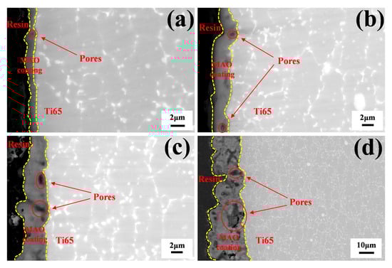
Figure 2.
Cross-sectional morphologies of various MAO coatings: (a) MAO-50, (b) MAO-100, (c) MAO-150, and (d) MAO-200.
Figure 3 shows the cross-sectional element distribution of various MAO coatings; it can be observed that the coating is enriched with large amounts of Ti, O, and Si elements, as well as a minor portion of Al, which is consistent with the surface EDS spectra data. The Si element in the substrate appears in the form of a Si-rich phase. In Figure 3d, a concentration of Al is observed in the coating, which may be due to the infiltration of Al2O3 alumina particles into the larger pores of the coating during the polishing process.
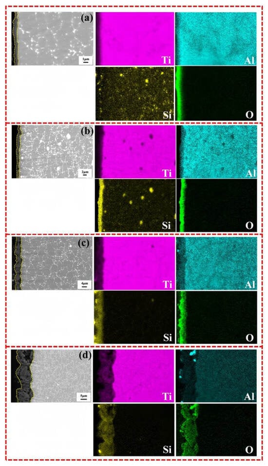
Figure 3.
SEM images and EDS element distribution along cross-section of various MAO coatings: (a) MAO-50, (b) MAO-100, (c) MAO-150, and (d) MAO-200.
3.1.3. Phase Composition of the MAO Coatings
Figure 4 is the XRD phase patterns of the Ti65 substrate and the MAO coatings prepared under different cathodic voltages. It can be observed that the phase of the Ti65 substrate is Ti, and the peak positions of the Ti in the MAO coatings show little change. This is because the MAO coatings are thin, and X-rays penetrate through the coating and hit the substrate, so the peaks mainly correspond to the Ti peaks of the substrate. Additionally, since the MAO coatings are porous, X-rays pass more easily through the voids and strike the substrate. As the cathodic voltage increases, the coating thickness increases, and oxide phases begin to appear. The main oxide phases are rutile TiO2 (R-TiO2) and anatase TiO2 (A-TiO2), confirming that the large amounts of O and Ti detected by EDS are present in the form of oxides.
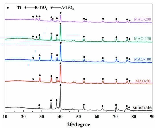
Figure 4.
XRD patterns of Ti65 alloy and various MAO coatings.
Through XRD analysis, no phases containing Si elements were detected. This is because the additional phases generated by the electrolyte decomposition may appear as an amorphous structure or crystalline form in the coating, but their content is below the detection limit of XRD. Therefore, XPS was used to detect the form of Si in the coatings. The thickest coating, MAO-200, was selected for XPS analysis. Figure 5a shows the high-resolution XPS spectra of Ti2p, Si2p, and O1s, with all peaks calibrated to the C1s peak at 284.8 eV. According to the literature [51,52], Ti2p can be deconvoluted into two peaks, Ti2p3/2 (459.09 eV) and Ti2p1/2 (464.82 eV), corresponding to the Ti4+oxidation state, indicating an increase in Ti activity and the formation of TiO2 through inward diffusion of O, consistent with the XRD results. The Si2p spectrum shows a single peak at 102.75 eV, corresponding to Si-O bonding [53]. The O1s spectrum can be deconvoluted into two peaks: one at 531.66 eV corresponding to the -OH group or oxygen vacancies [54], and the other at 532.75 eV corresponding to O2− [55,56], which corresponds to SiO2 and TiO2 oxides. SiO32− in the electrolyte participates in the formation of the MAO ceramic coating under high voltage, but due to “liquid quenching,” it generally exists in an amorphous SiO2 form throughout the coating [57]. Since the coating is thin (less than 10 μm), the crystalline SiO2 content is low, leading to no diffraction peaks being observed in the XRD spectrum [58]. No Al was detected in the XPS results, likely because when the element content is below 5%, XPS may fail to detect it. Based on the oxidation states of O detected by XPS, the presence of Al is likely in the form of trace Al2O3. Combining the XRD, XPS, and EDS results, it is concluded that the main components of the Ti65 alloy MAO coating are R-TiO2, A-TiO2, amorphous SiO2, and a small amount of Al2O3.
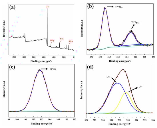
Figure 5.
XPS fine-scan profiles of MAO coatings (a) full-spectrum profile; (b) Ti2p; (c) Si2p; (d) O1s.
3.2. Coating Properties
3.2.1. Thermal Shock Property of the MAO Coatings
The thermal shock resistance of the coating is a critical parameter that significantly influences the application potential of these materials. After heat treatment at 700 °C for 5 min and cooling in water at 25 °C, the samples were subjected to repeated thermal shock for 50 cycles. The mass of the sample exhibited minimal variation as the number of thermal shock cycles increased. The macro morphology of the coatings showed no signs of spallation, indicating that the coatings possess excellent adhesion to the substrate. The outstanding thermal shock resistance of the coatings is related to the unique coating structure formed on the titanium surface by the micro-arc oxidation method. The large number of pores in the coatings allowed microcracks generated during thermal shock to propagate in multiple directions, thus inhibiting the formation of large cracks. This also reduced the diffusion speed of thermal flow and the temperature variation rate of the substrate. Additionally, the pore structure helped to decrease the thermal stress at the coating–substrate interface.
3.2.2. High-Temperature Oxidation Resistance of the MAO Coatings
Figure 6 shows the oxidation weight gain curves of the Ti65 alloy and MAO coatings after cyclic oxidation at 750 °C. The results show that both the Ti65 substrate and the MAO coatings increased in weight as oxidation time progressed. All samples formed oxide layers during the 100 h cyclic oxidation process at 750 °C. However, the weight gain varied between the samples. The Ti65 substrate showed the highest weight gain, while the MAO-50 coating showed the largest weight gain among the MAO coatings, indicating poor protection for the substrate. The MAO-150 and MAO-200 coatings showed moderate weight gains, and the weight gain curves of these coatings exhibited a quasi-linear increase. The MAO-100 coating showed the least weight gain of 0.5045 mg/cm2, which is only one-third of the weight gain of the substrate. This indicates that the MAO-100 coating effectively prevents O2 from corroding the substrate and provides excellent high-temperature oxidation resistance. The MAO-150 and MAO-200 coatings, with larger pores, offered lower resistance to O2 and showed greater weight gain.
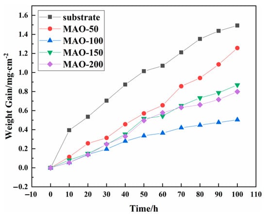
Figure 6.
Weight gain vs. oxidation time of the bared and coated Ti65 specimens during cyclic oxidation at 750 °C.
To analyze the oxidation kinetics, the weight gain was fitted using the following equation [59]:
where ΔM is the weight gain per unit area (mg/cm2), n is the exponent, kn is the oxidation reaction rate constant (mgn/(cm2n·h)), and t is the oxidation time (h). The values of n and kn were obtained through fitting using the Allometricl function tool embedded in the Origin software (Origin 8.5).
The test results are shown in Table 3. Based on the oxidation reaction rate constant Kn, the MAO-100 coating has the lowest oxidation rate constant (Kn = 0.003 mgn/(cm2n·h)), indicating better oxidation resistance. Therefore, it can be concluded that the sample prepared at a cathodic voltage of 100 V is suitable for preventing oxidation of the Ti65 substrate under high-temperature conditions at 750 °C.
Table 3.
Performance parameters of Ti65 alloy with various MAO coatings.
After 100 h of isothermal oxidation at 750 °C in air, the oxidation weight gain of the Ti65 alloy substrate and the Cr2AlC coating fabricated on Ti65 by magnetron sputtering was about 0.90 and 0.25 mg·cm−2, respectively [43], which were lower than the oxidation weight gain of the MAO-100 coating after 100 h of oxidation at the same temperature in this work. This difference is primarily attributed to the distinct oxidation methodologies employed. After a cyclic oxidation at a higher temperature of 800 °C for 100 h, the oxidation weight gain of the Cr-added Ti-Al-Si composite coatings prepared by the two-step hot-dipping + pre-oxidation method on Ti65 alloy varied between about 1.5 and 6.5 mg·cm−2 [41], which was significantly higher than the weight gain of the MAO-10 coating.
After cyclic oxidation at 750 °C, the XRD patterns of the Ti65 substrate and coatings were generated, which are shown in Figure 7. It can be observed that the Ti65 alloy substrate surface formed a high-temperature oxide layer, primarily consisting of a large amount of R-TiO2, a small amount of A-TiO2, and Al2O3. Compared to the coatings, the oxide layer formed on the substrate contains more oxide phases. Compared to Figure 4, the phase composition of the MAO coatings showed little change, with peaks corresponding to R-TiO2, A-TiO2, and Ti substrate phases. Additionally, a new peak for Al2O3 appeared, which is due to the oxidation of Al from the Ti65 alloy substrate at high temperature, increasing the amount of Al2O3 detected by XRD. After 750 °C cyclic oxidation, the amount of oxide phases on the coating surface significantly increased, indicating high-temperature oxidation occurred. Among the four coatings, the MAO-100 coating showed the least amount of oxide phases and the strongest Ti peak. As the cathodic voltage increased, the coating thickness increased, leading to a weakening of the Ti peak and a slight increase in oxide phases.
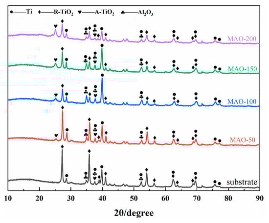
Figure 7.
XRD phase composition of Ti65 alloy and various MAO coatings after cyclic oxidation at 750 °C.
Figure 8 shows the surface morphologies of the Ti65 alloy and various MAO coatings after cyclic oxidation at 750 °C. After high-temperature oxidation, the Ti65 alloy substrate surface formed a gray oxide layer. Under high magnification, the oxide layer appeared granular, which is typical of high-temperature oxidation of metals. The EDS results show that the high-temperature oxide layer on the Ti65 substrate mainly consists of Ti, O, and Al elements. Based on XRD results, the oxide layer consists primarily of R-TiO2, A-TiO2, and Al2O3. Since the Al element originates from the Ti65 alloy substrate, the comparison of EDS results shows that the amount of Al on the coating surface is much lower than on the substrate, indicating that the substrate under the coating experienced less oxidation compared to the uncoated sample. In contrast to the high-temperature oxide film on the substrate, the MAO coatings developed a large amount of white “ice crystal”-like oxides in the pores of the porous structure after high-temperature oxidation, as shown in the XRD results. These white oxides are mainly R-TiO2 and A-TiO2, filling the pores on the coating surface. The MAO-50 sample, after 100 h of cyclic oxidation, showed significant spallation, severely reducing the protection for the substrate. The surface after spallation displayed a three-layer structure: the MAO layer, the first spalled layer, and the second spalled layer. The MAO-100 sample exhibited a uniformly filled pore structure with white oxides, forming a dense oxide layer and providing good sealing. For the MAO-150 sample, the surface also showed white oxide growth, but did not completely fill the micropores, which is related to the pore size. When the cathodic voltage reached 200 V, due to the large pore sizes and thicker coating, the high-temperature oxide grew within the porous structure, with only a small amount of white oxide visible on the surface, as shown in the red circle in Figure 8k. The white oxide was insufficient to fill the pores.
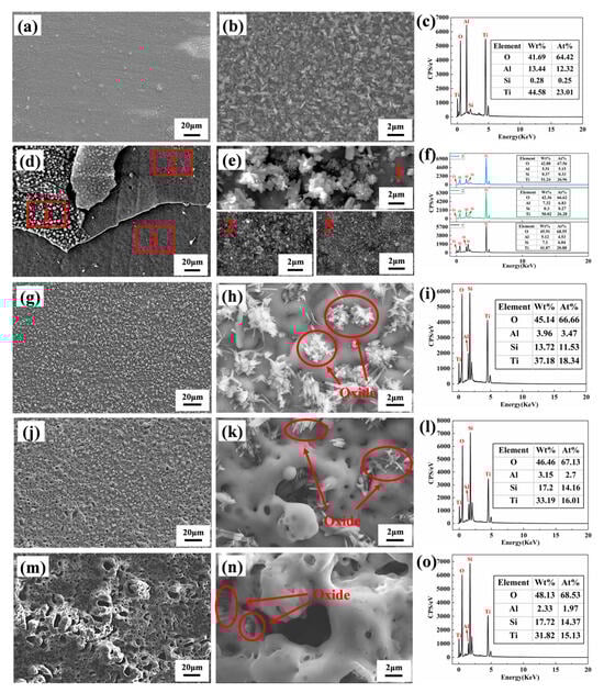
Figure 8.
SEM surface morphologies and EDS elements composition of Ti 65 alloy and various MAO coatings after cyclic oxidation at 750 °C: (a–c) Ti65 alloy, (d–f) MAO-50, (g–i) MAO-100, (j–l) MAO-150, and (m–o) MAO-200. The morphologies of samples 1, 2, and 3 in Figure (e) are magnified views corresponding to the labeled positions 1, 2, and 3 in Figure (d), respectively.
Figure 9 shows the cross-sectional morphology of the Ti65 alloy substrate and MAO coatings after 100 h of high-temperature oxidation at 750 °C. Figure 9a–d correspond to the cross-sections of the Ti65 alloy, MAO-50, MAO-100, MAO-150, and MAO-200 coatings, respectively. Due to the cyclic oxidation process, alternating heating and cooling induced significant thermal stress and tensile stress within the coatings. Both the MAO coating and the high-temperature oxidation layer became brittle. During cross-sectional sample preparation and polishing, mechanical forces may have caused fragmentation and spallation. Therefore, in this study, a chemical nickel plating process was used to deposit a nickel layer on the coating surface, which encapsulated the MAO coating and the high-temperature oxidation layer to provide protection. The bright white layer in Figure 10 represents this nickel-plated layer. After high-temperature oxidation, since the Ti65 alloy substrate lacked any protective coating, O2 rapidly reacted with the substrate, forming a high-temperature oxidation layer approximately 4.21 μm thick after 100 h of cyclic oxidation. The MAO-50 coating exhibited severe spallation, losing almost all protective effects for the substrate. Consequently, an oxidation layer of approximately 4.17 μm formed at the interface between the substrate and the coating, similar in thickness to the oxidation layer formed on the uncoated Ti65 alloy substrate. The MAO-100 sample exhibited an oxidation layer thickness of approximately 2.49 μm. The interface growth details are shown in Figure 9c, where TiO2 grew within the micropores of the MAO coating. As seen in Figure 8h, white “ice crystal-like” oxides were observed, which combined with the coating to increase its density. This interlocking effect improved the coating’s resistance to spallation. The oxidation layer thicknesses for the MAO-150 and MAO-200 samples were approximately 4.26 μm and 2.95 μm, respectively. After high-temperature exposure, the cross-sections revealed significant surface protrusions, increased roughness, and non-uniform coatings with poor density. Due to the large coating pores, a significant amount of metallic nickel grew within the pores during the electroless nickel plating process, filling the voids.
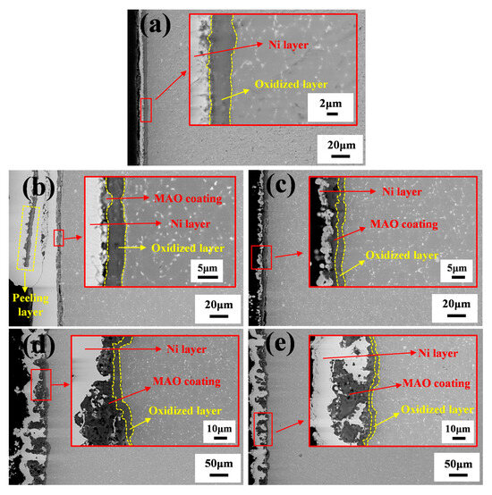
Figure 9.
Cross-sectional morphologies of Ti65 alloy and various MAO coatings after cyclic oxidation at 750 °C: (a) Ti65 alloy, (b) MAO-50, (c) MAO-100, (d) MAO-150, and (e) MAO-200.
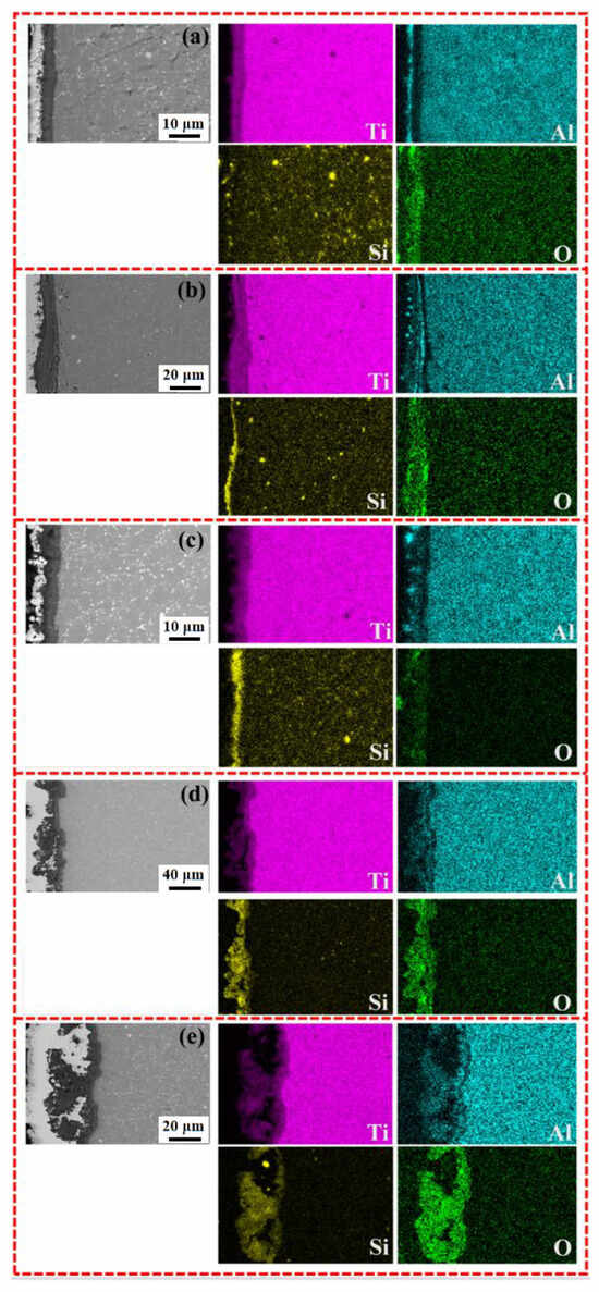
Figure 10.
SEM images and EDS element distribution along cross-section of Ti65 alloy and various MAO coatings after cyclic oxidation at 750 °C: (a) Ti65 alloy, (b) MAO-50, (c) MAO-100, (d) MAO-150, and (e) MAO-200.
Figure 10 shows the EDS elemental distribution of the cross-sections of the Ti65 alloy substrate and MAO coatings prepared at different cathodic voltages after cyclic oxidation at 750 °C. From the cross-sectional elemental distribution, it can be observed that after high-temperature oxidation, the MAO coating, located near the nickel-plated layer, exhibits a concentration of Si and O elements. However, at the interface between the MAO coating and the substrate, the Si content gradually decreased, while Ti and O elements became enriched. This indicates that during high-temperature oxidation, O elements penetrated through the coating and reacted with the substrate, forming a high-temperature oxidation layer at the interface between the substrate and the MAO coating. This finding is consistent with the cross-sectional morphology analysis in Figure 9.
The cathode voltage exerts a significant influence on the thickness, porosity, and pore size of the MAO coatings formed on Ti65 alloy. The data in Table 2 show that the porosity on the surface of MAO-150 and MAO-200 coatings is as high as 14%–15.5%, which is much higher than 3.0%–3.4% of MAO-50 and MAO-100 coatings. Under high-temperature oxidation conditions of 750 °C, oxygen diffuses inward through the different MAO coatings and oxidizes with the substrate elements to form a new oxide film. Therefore, the oxidation weight gain rate of MAO-150 and MAO-200 coatings is significantly higher than that of MAO-50 and MAO-100 coatings. This observation aligns with the fact that the weight gain curves of the MAO-150 and MAO-200 coatings, as depicted in Figure 6, exhibit a trend closely approximating linear growth. For the MAO-50 and MAO-100 coatings, although their surface porosity is similar, the pore size on the surface of the MAO-50 coating is larger than that of the MAO-100 coating. This results in an uneven high-temperature oxidation at the interface between the substrate and the MAO coating. Localized oxidation is particularly pronounced, leading to excessive compressive stress in those regions. Furthermore, the MAO-50 coating itself is relatively thin. Under significant compressive stress, cyclic oxidation accelerates, ultimately leading to premature spallation of the oxide film.
The surface porosity of the MAO-100 coating is the lowest, with small and uniformly distributed pores. During high-temperature oxidation, a newly formed oxide film is relatively evenly distributed at the interface between the substrate and the MAO coating. Concurrently, certain oxide films exhibit outward growth, filling the surface voids of the MAO coating. Once a continuous internal oxide layer is formed, it works in conjunction with the outward-growing oxide films to collectively inhibit the inward diffusion of oxygen. During the cyclic oxidation process at 750 °C, the weight gain curve of the MAO-100 coating initially exhibits a linear relationship, followed by a parabolic-like relationship. This behavior indicates that the MAO-100 coating demonstrates the best resistance to high-temperature cyclic oxidation.
4. Conclusions
- (1)
- Novel high-temperature oxidation-resistant ceramic coatings were fabricated on Ti65 alloy using MAO technology. The ceramic coatings primarily consisted of abundant amorphous SiO2, rutile TiO2 (R-TiO2), minor anatase TiO2 (A-TiO2), and trace Al2O3. All coatings fabricated at varied cathodic voltages demonstrated superior thermal shock resistance.
- (2)
- The influence of the cathodic voltage on microstructure and high-temperature oxidation performance at 750 °C of the MAO coatings was studied. The average surface pore size and surface porosity of the coatings show a trend of first decreasing and then increasing with the increase in cathodic voltage. The MAO-100 coating (with cathodic voltage of 100 V), with the smallest pore size and surface porosity, exhibited minimal oxidation weight gain after elevated-temperature exposure, only one-third that of the bare Ti65 substrate.
- (3)
- During the high-temperature oxidation process, new oxide layers were primarily formed at the interface between the MAO coating and the substrate, while simultaneously growing outward and progressively filling the micropores within the MAO coating. For the MAO-100 coating, the tendency for oxidation weight gain decreased significantly once the micropores within the coating were fully filled.
Author Contributions
Conceptualization, H.L.; methodology, Y.M.; investigation, H.L. and B.L.; data curation, B.L. and X.W.; formal analysis, Y.M.; writing—original draft preparation, H.L. and Y.M.; writing—review and editing, H.L. and Y.M.; supervision, H.Z. All authors have read and agreed to the published version of the manuscript.
Funding
This work is financially supported by the National Natural Science Foundation of China (No.52371097), Fundamental Research Funds for the Universities of Liaoning Province (No.LJ232410143034 and No.LJ232410143005), and Liaoning Provincial Natural Science Foundation of China (No.2024-BS-152).
Institutional Review Board Statement
Not applicable.
Informed Consent Statement
Not applicable.
Data Availability Statement
The original contributions presented in this study are included in the article. Further inquiries can be directed to the corresponding author.
Conflicts of Interest
Author Haitao Li was employed by the Aviation Industry Corporation of China. The remaining authors declare that the research was conducted in the absence of any commercial or financial relationships that could be construed as a potential conflict of interest.
References
- Antunes, R.A.; Salvador, C.A.F.; Oliveira, M.C.L. Materials selection of optimized titanium alloys for aircraft applications. Mater. Res. 2018, 21, e20170979. [Google Scholar] [CrossRef]
- Zhang, W.; Fan, J.; Huang, H.; Xue, X.; Wang, Y.; Zhang, B.; Jiang, P.; Wang, C.; Kou, H.; Li, J. Creep anisotropy characteristics and microstructural crystallography of marine engineering titanium alloy Ti6321 plate at room temperature. Mater. Sci. Eng. A 2022, 854, 143728. [Google Scholar] [CrossRef]
- Wang, L.; Zhao, X.; Wang, X.; Shang, S.; Xiu, Z.; Xi, Y.; Jia, H.; Xu, S.; Liu, H.; Wen, L.; et al. Current Status Review of Corrosion Resistance Applications of Titanium Alloys in the Petroleum Industry. Coatings 2024, 14, 941. [Google Scholar] [CrossRef]
- Zhang, L.C.; Chen, L.Y. A review on biomedical titanium alloys: Recent progress and prospect. Adv. Eng. Mater. 2019, 21, 1801215. [Google Scholar] [CrossRef]
- Zhu, S.; Zhu, C.; Luo, D.; Zhang, X.; Zhou, K. Development of a low-density and high-strength titanium alloy. Metals 2023, 13, 251. [Google Scholar] [CrossRef]
- Kang, L.M.; Yang, C. A review on high-strength titanium alloys: Microstructure, strengthening, and properties. Adv. Eng. Mater. 2019, 21, 1801359. [Google Scholar] [CrossRef]
- Zhao, Y.; Wang, H.; Meng, F.; Wang, L.; Xu, Q.; Zhou, T.; Wu, J. Formation of hydrogen resistant oxides of titanium alloy in water corrosion environment. J. Mater. Res. Technol. 2024, 33, 7293–7302. [Google Scholar] [CrossRef]
- Baltatu, M.S.; Tugui, C.A.; Perju, M.C.; Benchea, M.; Spataru, M.C.; Sandu, A.V.; Vizureanu, P. Biocompatible titanium alloys used in medical applications. Rev. Chim. 2019, 70, 1302–1306. [Google Scholar] [CrossRef]
- Qu, S.J.; Tang, S.Q.; Feng, A.H.; Feng, C.; Shen, J.; Chen, D.L. Microstructural evolution and high-temperature oxidation mechanisms of a titanium aluminide based alloy. Acta Mater. 2018, 148, 300–310. [Google Scholar] [CrossRef]
- Gloria, A.; Montanari, R.; Richetta, M.; Varone, A. Alloys for aeronautic applications: State of the art and perspectives. Metals 2019, 9, 662. [Google Scholar] [CrossRef]
- Williams, J.C.; Boyer, R.R. Opportunities and issues in the application of titanium alloys for aerospace components. Metals 2020, 10, 705. [Google Scholar] [CrossRef]
- Dong, E.; Yu, W.; Cai, Q.; Cheng, L.; Shi, J. High-temperature oxidation kinetics and behavior of Ti-6Al-4V alloy. Oxid. Met. 2017, 88, 719–732. [Google Scholar] [CrossRef]
- Dai, J.; Zhu, J.; Chen, C.; Weng, F. High temperature oxidation behavior and research status of modifications on improving high temperature oxidation resistance of titanium alloys and titanium aluminides: A review. J. Alloys Compd. 2016, 685, 784–798. [Google Scholar] [CrossRef]
- Satko, D.P.; Shaffer, J.B.; Tiley, J.S.; Semiatin, S.L.; Pilchak, A.L.; Kalidindi, S.R.; Kosaka, Y.; Glavicic, M.G.; Salem, A.A. Effect of microstructure on oxygen rich layer evolution and its impact on fatigue life during high-temperature application of α/β titanium. Acta Mater. 2016, 107, 377–389. [Google Scholar] [CrossRef]
- Li, S.; Deng, T.; Zhang, Y.; Liang, Y.; Li, R.; Dong, T. Review on the creep resistance of high-temperature titanium alloy. Trans. Indian Inst. Met. 2021, 74, 215–222. [Google Scholar] [CrossRef]
- Mordyuk, B.N.; Voloshko, S.M.; Zakiev, V.I.; Burmak, A.P.; Mohylko, V.V. Enhanced resistance of Ti6Al4V alloy to high-temperature oxidation and corrosion by forming alumina composite coating. J. Mater. Eng. Perform. 2021, 30, 1780–1795. [Google Scholar] [CrossRef]
- Dai, J.; Zhu, J.; Zhuang, L.; Li, S. Effect of surface aluminizing on long-term high-temperature thermal stability of TC4 titanium alloy. Surf. Rev. Lett. 2016, 23, 1550102. [Google Scholar] [CrossRef]
- Haanappel, V.A.C.; Clemens, H.; Stroosnijder, M.F. The high temperature oxidation behaviour of high and low alloyed TiAl-based intermetallics. Intermetallics 2002, 10, 293–305. [Google Scholar] [CrossRef]
- Zhao, R.T.; Sun, S.C.; Zhang, Y.Y. Recent advances in silicon containing high temperature titanium alloy. J. Mater. Res. Technol. 2021, 14, 3029–3042. [Google Scholar] [CrossRef]
- Xu, Y.; Fu, Y.; Li, J.; Xiao, W.; Zhao, X.; Ma, C. Effects of tungsten addition on the microstructural stability and properties of Ti-6.5 Al-2Sn-4Hf-2Nb-based high temperature titanium alloys. J. Mater. Sci. Technol. 2021, 93, 147–156. [Google Scholar] [CrossRef]
- Lee, D.B. Effect of Cr, Nb, Mn, V, W and Si on high temperature oxidation of TiAl alloys. Met. Mater. Int. 2005, 11, 141–147. [Google Scholar] [CrossRef]
- Pflumm, R.; Donchev, A.; Mayer, S.; Clemens, H.; Schütze, M. High-temperature oxidation behavior of multi-phase Mo-containing γ-TiAl-based alloys. Intermetallics 2014, 53, 45–55. [Google Scholar] [CrossRef]
- Tegner, B.; Zhu, L.; Siemers, C.; Saksl, K.; Ackland, G. High temperature oxidation resistance in titanium–niobium alloys. J. Alloys Compd. 2015, 643, 100–105. [Google Scholar] [CrossRef]
- Gong, X.; Chen, R.R.; Fang, H.Z.; Ding, H.S.; Guo, J.J.; Su, Y.Q.; Fu, H.Z. Synergistic effect of B and Y on the isothermal oxidation behavior of TiAl-Nb-Cr-V alloy. Corros. Sci. 2018, 131, 376–385. [Google Scholar] [CrossRef]
- Gogia, A.K. High-temperature titanium alloys. Def. Sci. J. 2005, 55, 149. [Google Scholar] [CrossRef]
- Hosseini, S.H.; Mirdamadi, S.; Rastegari, S. Investigating efficiency of α-Al2O3 diffusion barrier layer in oxidation of EB-PVD NiCrAlY coatings. Surf. Eng. 2015, 31, 146–155. [Google Scholar] [CrossRef]
- Alhafian, M.-R.; Chemin, J.-B.; Valle, N.; El Adib, B.; Penoy, M.; Bourgeois, L.; Ghanbaja, J.; Barrirero, J.; Soldera, F.; Mücklich, F.; et al. Study of the oxidation mechanism at high temperature of nanofiber textured AlTiCrN coatings produced by physical vapor deposition using high-resolution characterization techniques. Corros. Sci. 2022, 201, 110226. [Google Scholar] [CrossRef]
- Bobzin, K.; Brögelmann, T.; Kalscheuer, C.; Liang, T. High temperature oxidation protection of γ-titanium aluminide using (Cr, Al) ON coatings deposited by high-speed physical vapor deposition. Surf. Coat. Technol. 2017, 332, 2–11. [Google Scholar] [CrossRef]
- Chen, D.; Colas, J.; Mercier, F.; Boichot, R.; Charpentier, L.; Escape, C.; Balat-Pichelin, M.; Pons, M. High temperature properties of AlN coatings deposited by chemical vapor deposition for solar central receivers. Surf. Coat. Technol. 2019, 377, 124872. [Google Scholar] [CrossRef]
- Zhu, L.; Zhang, Y.; Hu, T.; Leicht, P.; Liu, Y. Oxidation resistance and thermal stability of Ti (C, N) and Ti (C, N, O) coatings deposited by chemical vapor deposition. Int. J. Refract. Met. Hard Mater. 2016, 54, 295–303. [Google Scholar] [CrossRef]
- Zhuang, Q.; Zhang, P.; Li, M.; Yan, H.; Yu, Z.; Lu, Q. Microstructure, Wear Resistance and Oxidation Behavior of Ni-Ti-Si Coatings Fabricated on Ti6Al4V by Laser Cladding. Materials 2017, 10, 1248. [Google Scholar] [CrossRef]
- Sayyedan, F.S.; Enayati, M.H. On structure and oxidation behaviour of non-stoichiometric amorphous aluminium phosphate coating. Surf. Eng. 2019, 35, 670–676. [Google Scholar] [CrossRef]
- Saremi, M.; Valefi, Z.; Abaeian, N. Hot corrosion, high temperature oxidation and thermal shock behavior of nanoagglomerated YSZ-Alumina composite coatings produced by plasma spray method. Surf. Coat. Technol. 2013, 221, 133–141. [Google Scholar] [CrossRef]
- Ghosh, D.; Das, S.; Roy, H.; Mitra, S.K. Oxidation behaviour of nanostructured YSZ plasma sprayed coated Inconel alloy. Surf. Eng. 2018, 34, 22–29. [Google Scholar] [CrossRef]
- Reddy, G.M.S.; Prasad, C.D.; Shetty, G.; Ramesh, M.R.; Rao, T.N.; Patil, P. High-temperature oxidation behavior of plasma-sprayed NiCrAlY/TiO2 and NiCrAlY/Cr2O3/YSZ coatings on titanium alloy. Weld. World 2022, 66, 1069–1079. [Google Scholar] [CrossRef]
- Tsai, D.C.; Deng, M.J.; Chang, Z.C.; Kuo, B.H.; Chen, E.C.; Chang, S.Y.; Shieu, F.S. Oxidation resistance and characterization of (AlCrMoTaTi)-Six-N coating deposited via magnetron sputtering. J. Alloys Compd. 2015, 647, 179–188. [Google Scholar] [CrossRef]
- Liang, J.; Chen, S.; Zou, C.; Tian, C.; Wang, Z.; Liao, S. Influence of oxygen contents on the microstructure, high temperature oxidation and corrosion resistance properties of Cr-Si-O-N coatings. Coatings 2018, 8, 19. [Google Scholar] [CrossRef]
- Wang, X.; Zhang, H.; Liu, B.; Man, T.; Cui, X.; Liu, T.; Zhao, T.; Luhovskyi, Y.; Lu, S.; Nong, Z. Design, preparation, and tribological properties of novel wide temperature range self-lubricating coatings on TC4 alloy. Surf. Coatings Technol. 2025, 517, 132852. [Google Scholar] [CrossRef]
- Yao, W.; Wu, L.; Wang, J.; Jiang, B.; Zhang, D.; Serdechnova, M.; Shulha, T.; Blawert, C.; Zheludkevich, M.L.; Pan, F. Micro-arc oxidation of magnesium alloys: A review. J. Mater. Sci. Technol. 2022, 118, 158–180. [Google Scholar] [CrossRef]
- Zhang, Z.; Fan, J.; Tang, B.; Kou, H.; Wang, J.; Wang, X.; Wang, S.; Wang, Q.; Chen, Z.; Li, J. Microstructural evolution and FCC twinning behavior during hot deformation of high temperature titanium alloy Ti65. J. Mater. Sci. Technol. 2020, 49, 56–69. [Google Scholar] [CrossRef]
- Li, F.; He, W.; Hu, X. Effect of Cr on microstructure and high temperature oxidation resistance of Ti-Al-Si composite coatings prepared by two-step hot-dipping + pre-oxidation method on Ti65 alloy. Appl. Surf. Sci. 2024, 678, 161070. [Google Scholar] [CrossRef]
- Han, R.; Li, J.; Kong, L.; Liu, J.; Shan, X.; Cui, X.; Xiong, T. A novel phosphate-ceramic coating for high temperature oxidation resistance of Ti65 alloys. Ceram. Int. 2019, 45, 23895–23901. [Google Scholar] [CrossRef]
- Ma, K.; Li, Y.; Li, J. Long-term oxidation resistance of a Ti65 alloy with Cr2AlC coating by magnetron sputtering. Corros. Commun. 2025, 18, 66–75. [Google Scholar] [CrossRef]
- Li, G.; Ma, F.; Liu, P.; Qi, S.; Li, W.; Zhang, K.; Chen, X. Review of micro-arc oxidation of titanium alloys: Mechanism, properties and applications. J. Alloys Compd. 2023, 948, 169773. [Google Scholar] [CrossRef]
- Zhou, Y.H.; Chen, P.H.; Huang, D.N.; Wu, Z.Z.; Yang, T.; Kai, J.J.; Yan, M. Micro-arc oxidation for improving high-temperature oxidation resistance of additively manufacturing Ti2AlNb. Surf. Coat. Technol. 2022, 445, 128719. [Google Scholar] [CrossRef]
- Zhou, K.; Xie, F.; Wu, X.; Wang, S. Fabrication of high temperature oxidation resistance nanocomposite coatings on PEO treated TC21 alloy. Materials 2019, 13, 11. [Google Scholar] [CrossRef]
- Chi, J.; Zhang, H.; Song, S.; Zhang, W.; He, X.; Nong, Z.; Cui, X.; Liu, T.; Man, T. The impact of pre- and post-treatment processes on corrosion resistance of micro-arc oxidation coatings on Mg alloys: A systematic review. Materials 2025, 18, 723. [Google Scholar] [CrossRef]
- Hussein, R.; Nie, X.; Northwood, D. A spectroscopic and microstructural study of oxide coatings produced on a Ti-6Al-4V alloy by plasma electrolytic oxidation. Mater. Chem. Phys. 2019, 134, 484–492. [Google Scholar] [CrossRef]
- Li, Q.; Liang, J.; Liu, B.; Peng, Z.; Wang, Q. Effects of cathodic voltages on structure and wear resistance of plasma electrolytic oxidation coatings formed on aluminium alloy. Appl. Surf. Sci. 2014, 297, 176–181. [Google Scholar] [CrossRef]
- Liu, F.; Xu, J.; Yu, D.; Wang, F.; Zhao, L. Effects of cathodic voltages on the structure and properties of ceramic coatings formed on NiTi alloy by micro-arc oxidation. Mater. Chem. Phys. 2010, 121, 172–177. [Google Scholar] [CrossRef]
- Pérez-Larios, A.; Torres-Ramos, I.; Zanella, R.; Rico, J.L. Ti-Co mixed oxide as photocatalysts in the generation of hydrogen from water. Int. J. Chem. React. Eng. 2022, 20, 129–140. [Google Scholar] [CrossRef]
- Wang, Q.; Qiu, L.; Tan, X.; Liu, Z.; Gao, S.; Wang, R. Amorphous TiO2 granular nanodisks on porous Ti foam for highly effective solar cells and photocatalysts. J. Taiwan Inst. Chem. Eng. 2019, 102, 85–91. [Google Scholar] [CrossRef]
- Biaggi-Labiosa, A.; Solá, F.; Resto, O.; Fonseca, L.F.; González-Berríos, A.; De Jesús, J.; Morell, G. Nanocrystalline silicon as the light emitting material of a field emission displaydevice. Nanotechnology 2008, 19, 225202. [Google Scholar] [CrossRef]
- Wang, X.; Liu, Y.; Han, H.; Zhao, Y.; Ma, W.; Sun, H. Polyaniline coated Fe3O4 hollow nanospheres as anode materials for lithium ion batteries. Sustain. Energy Fuels 2017, 1, 915–922. [Google Scholar] [CrossRef]
- Ke, W.; Qin, X.; Palomino, R.M.; Simonovis, J.P.; Senanayake, S.D.; Rodriguez, J.A.; Zaera, F. Redox properties of TiO2 thin films grown on mesoporous silica by atomic layer deposition. J. Phys. Chem. Lett. 2023, 14, 4696–4703. [Google Scholar] [CrossRef]
- Nguyen, N.M.; Nguyen, Y.H.; Phan, H.N.; Phan, M.N.; Duc, D.D.; Nga, P.T.; Van Nguyen, M.; Nguyen, T.M.; Duong, V.Q.; Nguyen, K.C. Investigation of origin optical properties of TiO2/graphene nanohybrids. Mater. Lett. 2020, 276, 128042. [Google Scholar] [CrossRef]
- Xu, J.L.; Xiao, Q.F.; Mei, D.D.; Zhong, Z.C.; Tong, Y.X.; Zheng, Y.F.; Li, L. Preparation and characterization of amorphous SiO2 coatings deposited by mirco-arc oxidation on sintered NdFeB permanent magnets. J. Magn. Magn. Mater. 2017, 426, 361–368. [Google Scholar] [CrossRef]
- Wang, Y.; Hu, Z.; Wu, G.; Zhang, X.; Yin, Y.; Li, L.; Yao, J. Effect of laser power on the microstructure and wear resistance of TiO2-SiO2 ceramic coating by laser-assisted micro-arc oxidation on Ti6Al4V alloy. Surf. Coat. Technol. 2025, 497, 131764. [Google Scholar] [CrossRef]
- Kumar, S.; Narayanan, T.S.; Raman, S.G.S.; Seshadri, S. Thermal oxidation of Ti6Al4V alloy: Microstructural and electrochemical characterization. Mater. Chem. Phys. 2010, 119, 337–346. [Google Scholar] [CrossRef]
Disclaimer/Publisher’s Note: The statements, opinions and data contained in all publications are solely those of the individual author(s) and contributor(s) and not of MDPI and/or the editor(s). MDPI and/or the editor(s) disclaim responsibility for any injury to people or property resulting from any ideas, methods, instructions or products referred to in the content. |
© 2025 by the authors. Licensee MDPI, Basel, Switzerland. This article is an open access article distributed under the terms and conditions of the Creative Commons Attribution (CC BY) license (https://creativecommons.org/licenses/by/4.0/).