Abstract
In order to solve the problem of inadequate confinement provided by traditional rectangular stirrups in concrete square columns under stringent seismic fortification requirements, a spiral stirrup with a better constraint effect was used in the square columns in this study. Through a comprehensive analysis of test results, numerical simulations, and theoretical derivations, the seismic performance and shear capacity calculation methods of concrete square columns confined with five-spiral composite stirrups were investigated. This study provides pertinent technical data to facilitate the engineering application of such columns. The existing low-cycle repeated loading tests of 13 concrete square columns confined with five-spiral composite stirrups were collected and analyzed; some of these specimens were selected for finite element numerical simulation, and the simulation results were compared with the test results. The results indicate that the hysteresis curves and skeleton curves obtained from the numerical simulation agree well with the experimental curves, which verifies the rationality of the numerical simulation model proposed in this paper; post-peak load behavior reveals a pronounced compound confinement effect attributable to the five-spiral stirrups; during mid-to-late loading stages, the tensile stress in small spiral stirrups at intersections with larger spirals escalates rapidly, resulting in maximum transverse confinement within these areas. Based on the validated numerical simulation approach, a comprehensive analysis was performed to investigate the effects of axial compression ratio, shear-span ratio, spacing of small spiral stirrups, and diameter ratio of large-to-small spiral stirrups on the seismic performance of the specimens. The results demonstrate that when the spacing of large and small spiral stirrups is kept consistent, the specimens yield optimal strength and ductility. With the diameter of the central large-spiral stirrup fixed, either an increase or a decrease in the diameter of small spiral stirrups will induce varying degrees of reduction in both strength and ductility of the specimens. Furthermore, the five-spiral reinforced columns achieve the best overall seismic performance when the diameter of the central large spiral stirrup reaches the maximum allowable value for the cross-section, and the diameter of small spiral stirrups is set to one-third that of the large spiral stirrup. Finally, the shear mechanism and influencing factors of the shear capacity of the concrete square columns confined with five-spiral composite stirrups were discussed, and a practical formula for calculating the shear capacity of such columns was proposed.
1. Introduction
Traditional rectangular stirrups are commonly utilized for reinforced concrete square columns found in building structures. However, such stirrups exhibit insufficient confinement when higher seismic design requirements are imposed. In light of this, circular spiral stirrups with enhanced confinement effects have been proposed. In recent years, scholars have conducted corresponding research into the mechanical properties of multi-spiral composite stirrups.
Recent studies have demonstrated the superior performance of multi-spiral stirrup systems in concrete columns. Yin [1,2,3] identified four-spiral and five-spiral configurations as optimal among ten designs through low-cyclic loading tests; both configurations exhibited improved strength, ductility, and energy dissipation compared with conventional rectangular stirrups, with the five-spiral arrangement showing particularly enhanced confinement effectiveness. Ou’s [4,5] experimental investigation involving low-cyclic loading and flexural tests revealed that five-spiral stirrup columns maintain excellent performance characteristics, including gradual post-peak strength degradation, substantial failure displacements, and sustained flexural capacity even with a 16–29% reduction in the volumetric stirrup ratio. Under high axial compression, these columns typically fail through spiral reinforcement fracture rather than anchorage hook pull-out observed in conventional designs.
Further validation comes from Zheng [6], in which retrofitted specimens with five-spiral configurations achieved ultimate lateral displacement ratios of 0.046–0.063, exceeding code requirements for rare earthquakes by 2.30–3.15 times. Xiong [7] demonstrated that increasing the shear-span ratio or spiral diameter enhances ductility in five-spiral stirrups reinforced with GFRP seawater–sea sand concrete columns, while higher axial compression ratios and larger stirrup spacing degrade seismic performance. Wang [8] proposed a simplified finite element analysis method for analyzing the axial compression behavior of rectangular section columns constrained by interlocking multi-helix stirrups. This method can replace the Mander constrained concrete model to obtain the complete compression curve of the column.
Notably, material efficiency has been consistently validated. Wu Jing [9] and Weng Zhengqiang [10] reported reductions in rebar usage for five-spiral stirrup columns of 15% and 24%, while maintaining structural superiority. Lu Dehui [11] confirmed that compared with cast-in-place ordinary composite stirrup columns, prefabricated five-spiral stirrup RC columns demonstrate significant advantages in seismic performance, particularly in terms of post-peak load-bearing capacity and ductility. Ngo [12] studied the applicability of the classical calculation method to the calculation of the maximum bending strength of multi-helix stirrup columns. The results showed that various classical methods do not fit well with the experimental results. Numerical simulations by Liu Yue [13] quantified these improvements, showing five-spiral columns achieving 1.14, 1.87, and 3.08 times the peak load, ductility, and energy dissipation of conventional columns under equivalent reinforcement quantities.
Existing studies have demonstrated that concrete columns confined with five-spiral composite stirrups exhibit superior mechanical performance and more pronounced economic benefits compared with conventional reinforced concrete columns. However, research in this area remains constrained by several critical limitations: (1) the composite confinement mechanism of five-spiral stirrups has not been systematically elucidated; (2) a comprehensive evaluation framework for assessing the seismic performance of such confined columns is still lacking; and (3) the design optimization methodology for multi-spiral composite stirrups has yet to be fully developed.
In summary, research into the seismic performance and design methodologies for square concrete columns confined by multi-spiral composite stirrups remains notably limited. The relevant design theories and methodologies for this column type are urgently required to be supplemented and refined. In response to these research needs, based on the analysis of existing experimental results, finite element numerical simulations, and theoretical derivations, the seismic performance and shear capacity calculation methods for square concrete columns confined by multi-spiral stirrups are systematically investigated in this study.
2. Existing Experimental Studies
Low-cyclic loading test data were collected from 13 groups of square concrete columns confined by five-spiral stirrups, as reported by Yin [3], Ou [4,5], Wu Jing [9], Weng Zhengqiang [10], and Lu Dehui [11]. Detailed specimen parameters are summarized in Table 1, with stirrup configurations illustrated in Figure 1. The specimen designation follows the format: Serial Number-Stirrup Configuration-Axial Compression Ratio, where “S5” denotes the five-spiral composite stirrup configuration. To facilitate unified analysis, this paper refers to the research of scholar Weng Zhengqiang [10] and uniformly calculates the volume reinforcement ratio of all specimens. At the same time, the compressive strength of the concrete cylindrical specimens cited in all references is converted into cube compressive strength and axial compressive strength.

Table 1.
Summary of specimen parameters.
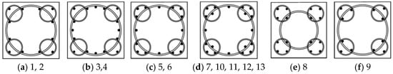
Figure 1.
Stirrup form.
3. Numerical Simulation and Validation
3.1. Numerical Model
Four five-spiral reinforced concrete specimens were selected as reference cases for numerical simulation analysis: specimens 10-S5-0.1 and 11-S5-0.3 that failed in shear, and specimens 12-S5-0.1 and 13-S5-0.3 that exhibited flexural failure.
The Concrete Damage Plasticity Model (CDP Model) was employed to characterize concrete behavior, which was originally established by Lubliner et al. [14] and subsequently improved by Lee and Fenves [15]. For concrete in the tensile region and unconfined concrete under compression, the uniaxial stress–strain relationships followed the provisions of GB50010-2015 [16]. The constitutive model for the confined core concrete was based on Mander’s theory [17], while the reinforcement was simulated using Fang Zihu’s Modified Hysteretic Model [18] to indirectly consider steel–concrete bond-slip effects.
A separated modeling approach was adopted, with concrete elements defined as C3D8R and reinforcement elements as T3D2. After repeated trial calculations, to balance accuracy and computational efficiency, the mesh size for the concrete column body region is set to 100 mm, while the mesh size for the remaining sections is 200 mm. The mesh size for the reinforcement sections is uniformly set to 50 mm (Figure 2A). Interactions were defined using the Embedded method for steel–concrete integration and Coupling constraints between reference points and corresponding surfaces (Figure 2B). Boundary conditions comprise displacement boundary conditions and load boundary conditions. Displacement boundary conditions include fully fixed constraints at the column base beam and out-of-plane loading constraints at the column top loading beam. Load boundary conditions encompass a constant axial force at the column top and cyclic horizontal displacement loading at the column top (Figure 2C).
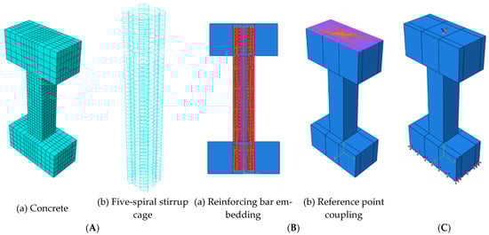
Figure 2.
Finite element modeling diagram: (A) grid division, (B) interaction, and (C) displacement and load boundary conditions.
3.2. Simulation Results Verification
Figure 3 compares the simulated and experimental hysteresis curves of the four specimens. Overall, the numerical simulations show good agreement with the experimental results. For shear-dominated specimens (10-S5-0.1 and 11-S5-0.3), the simulated hysteresis loops appear fuller with better energy dissipation characteristics, whereas the experimental curves display more pronounced pinching effects with distinct Z-shaped patterns. The reasons for this phenomenon can be attributed to two primary factors: firstly, the simplified model setup and partially idealized boundary conditions; secondly, in short columns with relatively small span-to-depth ratios, the slip between reinforcement and concrete is greater than in flexural specimens, resulting in more pronounced pinching in the hysteresis curves. For the flexural failure specimens 12-S5-0.1 and 13-S5-0.3, the simulated curves and experimental curves exhibit consistent fullness and pinching behavior. Therefore, excluding uncontrollable experimental factors and data processing errors, the established finite element model is reasonable.
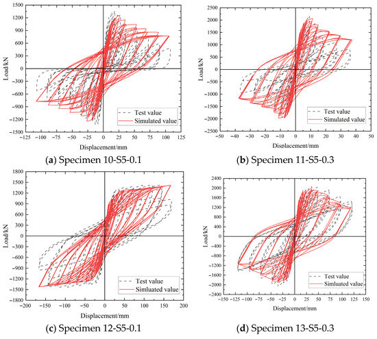
Figure 3.
Comparison of hysteresis curves of each specimen.
3.3. Stress Analysis of Five-Spiral Stirrups
Specimen 13-S5-0.3, which demonstrated the best simulated performance, was selected for detailed analysis of its five-spiral stirrup stresses at different loading stages, as illustrated in Figure 4. The results indicate that at the yield point, the large spiral stirrups experience higher stresses than the small corner spirals, while overall stirrup stresses remain relatively low due to limited concrete lateral deformation. As loading progresses to the peak point, stirrup stresses increase significantly, and the composite confinement effect of the five-spiral configuration becomes pronounced, substantially enhancing the core concrete confinement. At the ultimate stage, after the longitudinal reinforcement has yielded in compression, both the large spiral stirrups in the plastic hinge zone and some localized small spiral stirrups reach their tensile yield capacity.
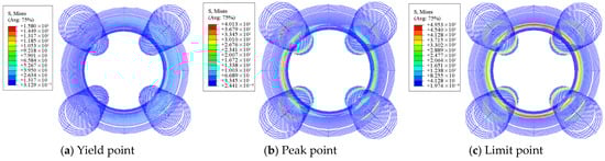
Figure 4.
Strain diagram of the five-spiral stirrup in specimen 13-S5-0.3.
4. Seismic Performance and Parametric Analysis
4.1. Parameter Design
To systematically investigate the seismic behavior and key influencing factors of square concrete columns reinforced with five-spiral stirrups, specimen 13-S5-0.3 (designated as M0) from the experimental program was selected as the reference case. The parametric study examined four key variables: axial compression ratio, shear-span ratio, spacing of small spiral stirrups, and diameter ratio between large and small spirals. Detailed parameter configurations are summarized in Table 2, with the corresponding stirrup arrangements illustrated in Figure 5 and Figure 6.
Table 2.
Parameter design of finite element analysis.
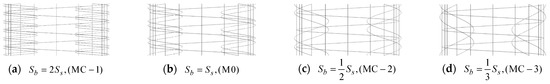
Figure 5.
Spiral spacing design of small spiral stirrup.
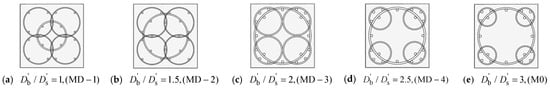
Figure 6.
Spiral diameter ratio design of large and small spiral stirrups.
Building on the fundamental principles of structural mechanics and considering the effects of loading direction, this study develops a stiffness degradation index based on the theoretical frameworks established by Chen [19] and Kunnath and Jenne [20]. The proposed formulation is expressed as follows:
In this formulation, parameters
and
correspond to the tangent stiffnesses in the positive and negative loading directions at the j-th cycle, respectively;
and
represent the corresponding tangent stiffnesses at yielding under positive and negative loading directions;
and
designate the stiffness degradation coefficients for the j-th cycle in the respective loading directions; and
indicates the mean stiffness degradation coefficient incorporating both positive and negative loading responses.
4.2. Parametric Analysis
4.2.1. Axial Compression Ratio
Figure 7 presents a comparative analysis of the hysteretic responses, skeleton curves, stiffness degradation patterns, and cumulative energy dissipation for specimens with varying axial compression ratios: MA-1 (n = 0.2), M0 (n = 0.3), MA-2 (n = 0.4), MA-3 (n = 0.5), and MA-4 (n = 0.6).
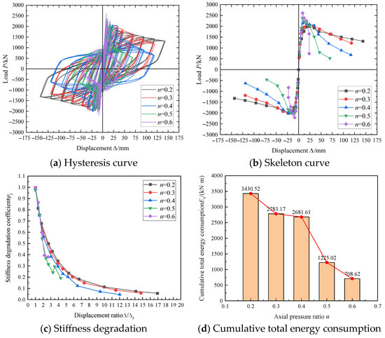
Figure 7.
Influence of axial pressure ratio.
Figure 7 reveals the following key observations regarding axial compression effects: (1) Increasing axial compression ratios intensify pinching behavior in hysteresis loops while substantially reducing their enclosed areas, indicating significant deterioration in energy dissipation capacity. (2) Although axial compression ratios minimally affect the ascending branches of skeleton curves, they markedly accelerate post-peak strength deterioration, manifested through steeper descending slopes and faster load capacity degradation. (3) Initial loading stages show nearly identical stiffness degradation patterns across specimens, whereas beyond the peak displacement (approximately 1.5
), higher axial compression ratios lead to systematically reduced stiffness retention despite moderated degradation rates. (4) Cumulative energy dissipation demonstrates an inverse relationship with axial compression ratios, with particularly dramatic reductions occurring between ratios of 0.4 and 0.5. When the axial compression ratio increased from 0.2 to 0.6, the displacement ductility coefficient of the specimen decreased from 16.36 to 3.13, with a reduction rate of 80.87% and a decrease rate of 79.34% in the total cumulative energy dissipation.
4.2.2. Shear-Span Ratio
Figure 8 presents a comparative analysis of hysteretic responses, skeleton curves, stiffness degradation, and cumulative energy dissipation for specimens with varying shear-span ratios: MB-1 ( = 2), MB-2 ( = 3), MB-3 ( = 4), MB-4 ( = 5), and MB-5 ( = 6).
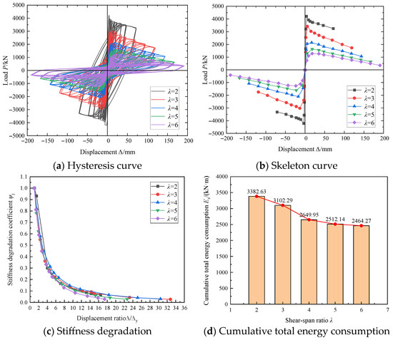
Figure 8.
Influence of shear span ratio.
Figure 8 demonstrates the following effects of shear-span ratio variation: (1) Increasing shear-span ratios result in progressively flattened hysteresis loops with enhanced pinching effects and reduced enclosed areas, indicating deteriorated energy dissipation capacity. (2) Higher shear-span ratios lead to significant reductions in peak load and gradually flattened descending branches in skeleton curves. (3) Although stiffness degradation patterns remain similar during initial loading phases, specimens with larger shear-span ratios exhibit accelerated stiffness deterioration beyond the peak point. (4) Cumulative energy dissipation decreases with increasing shear-span ratios, though this trend becomes less pronounced when the ratio exceeds 4, suggesting a threshold effect in energy dissipation reduction. When the ratio of span to height increases from 2 to 6 successively, the decrement of the ductility coefficient is 42.68%, 49.38%, 64%, and 71.53% respectively, and the cumulative energy dissipation total is reduced by 8.28%, 21.66%, 25.73%, and 27.15% respectively.
4.2.3. Spacing of Small Helical Stirrups
Figure 9 presents a parametric analysis of small spiral stirrup spacing effects under constant large spiral spacing (Sb = 90mm) examining the influence of varying small spiral spacing on hysteretic behavior, skeleton curves, stiffness degradation, and cumulative energy dissipation for specimens MC-1 (Ss = 45 mm), M0 (Ss = 90 mm), MC-2 (Ss = 180 mm), and MC-3 (Ss = 270 mm).
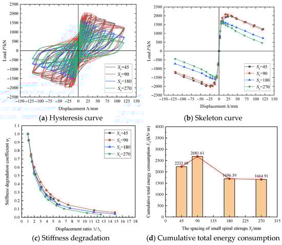
Figure 9.
Influence of small spiral stirrup spacing.
Figure 9 demonstrates that under constant large spiral spacing, reduced small spiral stirrup spacing produces fuller hysteresis loops with larger enclosed areas, indicating enhanced energy dissipation capacity. The peak load decreases with increased small spiral spacing, accompanied by slightly flattened descending skeleton curve branches. Specimen M0, featuring identical large and small spiral spacing (90 mm), achieves the maximum peak load. At identical displacement levels, the stiffness degradation coefficient decreases with larger small spiral spacing, with M0 exhibiting the highest stiffness retention. Similarly, cumulative energy dissipation reduces with increased spacing, where M0 demonstrates superior energy dissipation performance. Consequently, specimen M0 with identical 90 mm spiral spacing exhibits the most balanced structural performance.
4.2.4. Spiral Diameter Ratio of Large and Small Spiral Stirrups
Figure 10 presents the effects of spiral diameter ratios for large and small spiral stirrups on hysteretic behavior, skeleton curves, stiffness degradation, and cumulative energy dissipation. Specimens MD-1 ( = 1.0), MD-2 ( = 1.5), and MD-3 ( = 2) maintain identical small spiral diameters with varying large spiral diameters, while specimens MD-3 ( = 2), MD-4 ( = 2.5), and M0 ( = 3.0) share identical large spiral diameters with varying small spiral diameters.
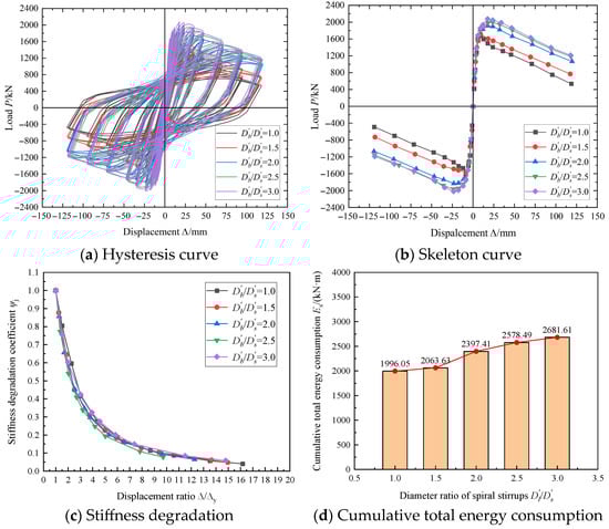
Figure 10.
Influence of the size spiral diameter ratio.
Figure 10 reveals the following observations: (1) All specimens exhibit similar hysteretic loop shapes, though the enclosed area progressively expands with increasing spiral diameter ratios, indicating enhanced energy dissipation capacity—a trend that diminishes beyond the ratio of 2.5. (2) Although the ascending branches of skeleton curves remain largely consistent across specimens, both the peak load and post-peak behavior improve with increasing diameter ratios, with this effect becoming less pronounced above 2.5. (3) The spiral diameter ratio shows negligible influence on stiffness degradation patterns. (4) Cumulative energy dissipation increases monotonically with diameter ratios, confirming the beneficial effect of larger spiral size differentials on energy absorption capacity.
Further analysis provides additional insights into the effects of spiral diameter variations. When comparing specimens MD-1, MD-2, and MD-3, where the diameter ratio increases from 1 to 2 through progressively larger large-spiral diameters while maintaining a constant small-spiral diameter, both strength and ductility properties demonstrate substantial enhancement.
In contrast, examination of specimens MD-3, MD-4, and M0 reveals a different pattern. As the diameter ratio increases from 2 to 3 through progressively smaller small-spiral diameters while maintaining the maximum permissible large-spiral diameter, only marginal improvements in strength and ductility are observed.
These comparative results indicate that variations in large-spiral diameter exert considerably greater influence on both strength and ductility than equivalent changes in small-spiral diameter. Consequently, optimal comprehensive performance is achieved when the large-spiral diameter reaches the maximum allowable value within the cross-sectional constraints, combined with a small-spiral diameter measuring one-third of the large-spiral dimension, as exemplified by specimen M0.
5. Shear Capacity Calculation
5.1. Shear Resistance Mechanism
Similar to conventional stirrup-confined concrete columns, the shear resistance in five-spiral reinforced concrete columns is primarily provided by concrete and transverse reinforcement, with additional contribution from axial compression. However, the interlocking spiral mechanism of five-spiral composite stirrups renders their shear resistance mechanism more complex.
Figure 11 shows the division of the five-spiral stirrup column’s sectional restraint zones. The interlocking design between the corner small spiral stirrups and the central large spiral stirrups divides the square column section into three zones with varying degrees of restraint: low, medium, and high. Therefore, the shear capacity of the concrete must be calculated separately for each zone before being superimposed. For the spiral stirrups, shear cracks and tensile stresses at their intersections are transmitted upward and downward along the spiral, respectively. This reduces stress concentration in the stirrups, thereby fully utilizing the tensile capacity of each stirrup segment. Additionally, the continuous longitudinal arrangement of the five-spiral stirrups ensures that the concrete within each confinement zone maintains its cylindrical integrity during failure. Additionally, increased axial force enhances the Poisson Effect in the constrained concrete zone, thereby strengthening the lateral confinement provided by the stirrups. Furthermore, axial force inhibits crack propagation.
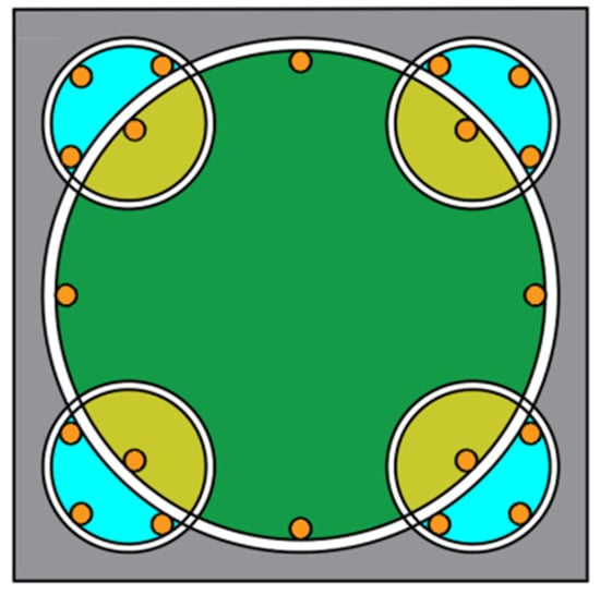
Figure 11.
Section constraint area division of five-spiral stirrup column: light blue, green, and yellow represent the low-constraint, medium-constraint, and high-constraint regions, respectively.
Based on the established shear resistance mechanisms and existing experimental data for five-spiral stirrup columns, and with reference to the Concrete Structure Design Code (GB50010-2015) [16] and Technical Specification (T/CECS 512-2018) [21], this study proposes a formula for calculating the shear capacity of five-spiral stirrup-constrained concrete square columns, as follows:
In the equation,
represents the total shear force in the column’s diagonal section;
and
denote the shear forces borne by the concrete and spiral stirrups, respectively;
is the favorable contribution of axial force to the diagonal section’s shear resistance;
is the seismic adjustment factor for bearing capacity;
is the shear-span ratio (set to 1 when less than 1, and to 3 when greater than 3);
and
are the width and effective height of the column section, respectively;
and
are the design tensile strengths of concrete and stirrups, respectively;
is the stirrup spacing;
is the cross-sectional area of the large spiral stirrups;
is the spiral diameter of the large spiral stirrups; and
is the design axial force corresponding to the design shear force ( taken as when greater than
, where
is the total cross-sectional area of the column).
5.2. Shear Strength of Concrete
5.2.1. Low-Constraint Zone
The concrete zone near the corners of the small spiral stirrups exhibits the least confinement force. As the concrete cover deteriorates, the confinement force exerted by the outermost concrete layer on this zone also diminishes. Considering that the tensile-to-compressive strength ratio for concrete of different strength grades ranges from 6.2% to 12.7% with an average of 8.67%, this study recommends approximating the tensile strength of concrete
in this zone as 1/10 of the concrete’s axial compressive strength
, disregarding any enhancement from confinement effects. The area of this low-confinement zone is conservatively set at 1/3 of the area confined by the small spiral stirrups
. Therefore, the calculation method for the shear capacity
borne by concrete in the low-constraint zone is as follows:
5.2.2. Medium-Constraint Zone
The medium-constraint zone constitutes the primary constraint region during the mid-to-late loading stages, featuring the largest hoop reinforcement area. Consequently, parameter values in shear capacity calculations for this zone must be more precise and reasonable. Concrete within this zone undergoes triaxial compression, simultaneously subjected to axial pressure and circumferential constraint from the large spiral hoop reinforcement, while also experiencing lateral squeezing from the highly constrained concrete at the four corners along the intersecting diagonal range. Using the tensile strength of ordinary concrete under axial loading would significantly underestimate the concrete strength in this zone. Therefore, this study employs the Mander Confined Concrete Model [17] to first determine the concrete’s axial compressive strength
within this confined zone. Subsequently, the corresponding axial tensile strength
is calculated using the tensile-compressive strength conversion formula [22,23], as shown below.
Additionally, the concrete area in the medium-constraint zone is obtained by subtracting the intersection area of the large and small spiral stirrups at the four corners from the total constraint area of the large spiral stirrups. The intersection area between the large and small spiral stirrups is taken as 2/3 of the constraint area
of the small spiral stirrups (corresponding to the low-constraint zone area mentioned above). Therefore, the shear capacity
borne by the concrete in the medium-constraint zone is calculated as follows:
where
is the axial compressive strength of the confined concrete calculated using the Mander Model;
is the cube compressive strength of the concrete; and
and
are the confinement areas of the large and small spiral stirrups, respectively.
5.2.3. High-Constraint Zone
The concrete in the intersection zone of large and small spiral stirrups experiences the highest confinement forces and exhibits a highly complex stress distribution, making its shear capacity difficult to derive directly from theory. Given that the Mander Model was employed to calculate the shear capacity of concrete in the medium-constraint zone, accounting for the enhancement of confinement effects, the shear capacity of the high-constraint zone can be determined as a fraction of
based on the area ratio (area of the intersection zone between large and small spiral stirrups/area of confinement by the central large spiral stirrups). Furthermore, based on the aforementioned research, a spiral diameter ratio of 3 between the large and small spiral stirrups was selected (superior comprehensive seismic performance). This results in the area ratio being calculated as 8/27. This area ratio is then multiplied by an enhancement factor of 1.1 to account for the complex confinement effects in the highly confined region. Therefore, the shear capacity
borne by the concrete in the highly confined region is:
In summary, the expression for the shear capacity
borne by the concrete portion in a five-spiral stirrup-constrained concrete square column is:
5.3. Shear Capacity of Stirrup Section
For the five-spiral composite stirrup, based on Formula (5), the contributions of the central large spiral stirrup and the four-corner small spiral stirrups to the shear resistance capacity are considered separately, as shown below:
In the equation,
and
represent the contributions to shear resistance after installing the large spiral stirrups and the four corner small spiral stirrups, respectively;
and
denote the yield strengths of the large and small spiral stirrups, respectively;
and
denote the cross-sectional areas of the large and small spiral stirrups, respectively;
and
denote the spiral diameters of the large and small spiral stirrups, respectively; and
is the spacing between spiral stirrups.
Therefore, the contribution
to shear resistance after installing the five-spiral composite stirrups is:
5.4. Axial Force Influence
The aforementioned studies indicate that the shear capacity of five-spiral stirrup reinforced concrete columns increases with rising axial compression ratio. Concurrently, research [24] demonstrates that the rate of increase in RC column shear capacity diminishes as axial force rises, reaching a plateau at high axial compression ratios. For five-spiral composite stirrups, given their superior confinement effect, the shear capacity of such columns under higher axial forces exceeds that of conventional stirrup columns. Therefore, by increasing the coefficient in Formula (6) from 0.056 to 0.06, the expression for axial force versus shear capacity
of five-spiral stirrup reinforced concrete square columns is derived as:
5.5. Shear Capacity Calculation for Square Concrete Columns Constrained by Five-Spiral Stirrups
The shear capacity of the concrete section and the five-spiral stirrup section are superimposed, taking into account the influence of axial force, to obtain the total shear capacity
of the five-spiral stirrup reinforced concrete square column:
To validate the reliability of Formula (19), calculations were performed for all collected specimens and compared with experimental values, with results shown in Table 3. The table indicates that the calculation errors for most specimens are within 10%, with the smallest error being only 0.30%. This demonstrates that Formula (19) proposed in this paper can be used to calculate the shear capacity of five-spiral stirrup-constrained RC columns considering seismic capacity adjustment. Additionally, specimens 4-S5-0.1 and 9-S5-0.3 exhibited larger errors of 12.88% and 14.11%, respectively. These discrepancies stemmed from errors introduced during the linear data fitting correction process.
Table 3.
Calculation and test values of shear capacity of five-spiral stirrup column specimens.
6. Conclusions
This study integrates experimental investigations, finite element simulations, and theoretical analyses to systematically examine the seismic behavior and key influencing factors of square concrete columns confined by five-spiral composite stirrups. The research further elucidates the shear resistance mechanism and identifies primary parameters governing the shear capacity of this structural system. The principal findings are summarized as follows:
- (1)
- The confinement effect of the five-spiral composite stirrups manifests predominantly in the post-peak loading phase. The central large spiral stirrup sustains tensile stresses throughout the entire loading process until ultimate failure. In contrast, the four corner small spirals contribute more significantly during initial loading stages by providing effective confinement to the corner concrete regions. As loading progresses to the middle and late stages, the small spirals located in the intersection zones with the large spiral experience rapid stress development, generating the highest lateral confinement pressure in these interaction regions.
- (2)
- Although increased axial compression ratios moderately enhance the load-bearing capacity of five-spiral composite stirrup columns, they substantially compromise member ductility. Higher shear-span ratios lead to significant deterioration in both load-bearing capacity and energy dissipation performance.
- (3)
- Specimen M0 (Figure 11) represents the optimal geometric configuration for a column constrained by five-spiral stirrups. When the spacing of small spiral stirrups is equal to that of large spiral stirrups, the specimen exhibits optimal strength and ductility, achieving the best overall performance. When the diameter of the central large spiral reaches the maximum allowable value for the cross-section, and the small spiral stirrups are one-third the diameter of the large spiral, the five-spiral stirrup column demonstrates the most favorable comprehensive performance. This configuration ensures the maximum possible area of core-constrained concrete.
- (4)
- For five-spiral stirrup-constrained concrete square columns, the interlocking design between the four corner small spiral stirrups and the central large spiral divides the cross-section into three zones with varying constraint levels: low, medium, and high. The concrete contribution to the column’s shear capacity is the sum of these three zones. Simultaneously, by separately considering the contributions of the central large stirrups and the four corner small stirrups, combined with a discrete calculation shear strength model, a simplified calculation formula for the shear capacity of five-spiral composite stirrups is proposed.
- (5)
- The shear capacity of the five-spiral stirrup reinforced concrete square columns comprises both the concrete portion and the stirrup portion, while also accounting for the influence of axial loads. Based on this, this study proposes a shear capacity calculation formula applicable to five-spiral composite stirrup-constrained concrete square columns. When compared with experimental results, the minimum error is 0.30%, with most errors falling within 10%.
Author Contributions
Conceptualization, S.S., Z.Z. and T.S.; Software, T.Y. and Z.H.; Data curation, T.Y.; Writing—original draft, X.G.; Writing—review & editing, S.S.; Funding acquisition, S.S. All authors have read and agreed to the published version of the manuscript.
Funding
The authors would like to acknowledge the financial support by the Open Foundation of Shock and Vibration of Engineering Materials and Structures Key Lab of Sichuan Province, China (No. 20kfgk04); the Natural Science Foundation of Shandong Province (No. ZR2025MS802).
Institutional Review Board Statement
Not applicable.
Informed Consent Statement
Not applicable.
Data Availability Statement
The original contributions presented in this study are included in the article. Further inquiries can be directed to the corresponding authors.
Conflicts of Interest
Author Zhixing Hao was employed by the company East China Architectural Design & Research Institute Co., Ltd. The remaining authors declare that the research was conducted in the absence of any commercial or financial relationships that could be construed as a potential conflict of interest.
References
- Samuel, Y. Researches and Developments of Alternative Confinements for Rectangular Concrete Columns (II). China Civ. Eng. J. 2004, 37, 1–12. [Google Scholar]
- Yin, S. Helical Rebar Structure. U.S. Patent US6860077B2, 1 March 2005. [Google Scholar]
- Yin, S.Y.L.; Wang, J.C.; Wang, P.H. Development of multi-spiral confinements in rectangular columns for construction automation. J. Chin. Inst. Eng. 2012, 35, 309–320. [Google Scholar] [CrossRef]
- Ou, Y.C.; Li, J.Y.; Roh, H. Shear strength of reinforced concrete columns with five-spiral reinforcement. Eng. Struct. 2021, 233, 111929. [Google Scholar] [CrossRef]
- Ou, Y.C.; Lau, J.V.J.; Li, J.Y.; Havlásek, P.; Bittnar, Z. Cyclic behavior of reinforced concrete columns with five-spiral reinforcement. J. Build. Eng. 2022, 61, 105245. [Google Scholar] [CrossRef]
- Zheng, W.; Hao, M.; Chang, W. Seismic behavior of full-scale RC columns jacketed by modified multi-spiral stirrups. Arch. Civ. Mech. Eng. 2022, 22, 158. [Google Scholar] [CrossRef]
- Xiong, Z.; Zheng, J.; Chen, Z.; Huang, Y.; Wang, Z.; Chen, J.; Lin, L.; Li, L.; Qiao, S.; Liu, F. Seismic behavior and design method of seawater sea-sand concrete reinforced with GFRP and five interlocking spirals. Eng. Struct. 2023, 291, 116410. [Google Scholar] [CrossRef]
- Wang, P.H.; Chang, K.C.; Yin, S.Y.L.; Wang, J.C.; Ou, Y.C. Simplified finite-element analysis method for axial compression behavior of rectangular concrete columns with interlocking multispiral reinforcements. J. Struct. Eng. 2020, 146, 04019176. [Google Scholar] [CrossRef]
- Wu, J. The Seismic Behavior of Multi-Spiral Stirrup Toughening Reforced Lightweight Concrete. Doctoral Dissertation, Wuhan University of Technology, Wuhan, China, 2010. [Google Scholar]
- Weng, Z.Q.; Yin, Y.L.; Wang, R.Z.; Liang, C.; Lin, G. Seismic Cyclic Loading Test of Full-Scale Reinforced Concrete Columns Confined with 5-Spirals. J. Struct. Eng. 2011, 26, 57–91. [Google Scholar]
- Lu, D.H.; Wu, Z.L.; Cao, J.Y.; Gong, C. Experimental Study on Seismic Resistance of Fabricated Five-screw-stirrup Column. Build. Constr. 2019, 41, 2237–2241. [Google Scholar]
- Ngo, S.H.; Ou, Y.C. Expected maximum moment of multi-spiral columns. Eng. Struct. 2021, 249, 113386. [Google Scholar] [CrossRef]
- Liu, Y. Study on Axial Compression Capacity and Seismic Performance of Innovative Five-Spiral Stirrup for Steel Rectangular Columns. Master’s Thesis, Southwest Jiaotong University, Chengdu, China, 2021. [Google Scholar]
- Lubliner, J.; Oliver, J.; Oller, S.; Onate, E. A plastic-damage model for concrete. Int. J. Solids Struct. 1989, 25, 299–326. [Google Scholar] [CrossRef]
- Lee, J.; Fenves, G.L. Plastic-damage model for cyclic loading of concrete structures. J. Eng. Mech. 1998, 124, 892–900. [Google Scholar] [CrossRef]
- GB50010-2015; Code for Design of Concrete Structures. China Architecture & Building Press: Beijing, China, 2015.
- Mander, J.B.; Priestley, M.J.; Park, R. Theoretical stress-strain model for confined concrete. J. Struct. Eng. 1988, 114, 1804–1826. [Google Scholar] [CrossRef]
- Fang, Z.H.; Zhen, Y.; Li, X.P. Steel hysteretic model of reinforced concrete structures. Eng. J. Wuhan Univ. 2018, 51, 613–619. [Google Scholar]
- Chen, Z.; Chen, J.; Jiang, X.; Mo, L. Experimental research and finite element analysis on seismic behavior of square reinforced concrete columns with four interlocking spirals. Structures 2022, 39, 1–16. [Google Scholar] [CrossRef]
- Kunnath, S.K.; Jenne, C. Seismic damage assessment of inelastic RC structures. In Proceedings of the 5th US National Conference on Earthquake Engineering (EERI), Chicago, IL, USA, 10–14 July 1994; Volume 1, pp. 55–64. [Google Scholar]
- T/CECS 512-2018; Technical Specification for Application of Multi-Spiral Columns. Planning Press: Beijing, China, 2018.
- Yu, Z.W.; Ding, F.X. Unified calculation method of compressive mechanical properties of concrete. J. Build. Struct. 2003, 24, 41–46. [Google Scholar]
- Ding, F.X.; Yu, Z.W. Unified Calculation Method of Mechanical Properties of Concrete in Tension. J. Civ. Eng. Manag. 2004, 5, 29–34. [Google Scholar]
- Ou, Y.C.; Kurniawan, D.P. Effect of axial compression on shear behavior of high-strength reinforced concrete columns. ACI Struct. J. 2015, 112, 209–220. [Google Scholar] [CrossRef]
Disclaimer/Publisher’s Note: The statements, opinions and data contained in all publications are solely those of the individual author(s) and contributor(s) and not of MDPI and/or the editor(s). MDPI and/or the editor(s) disclaim responsibility for any injury to people or property resulting from any ideas, methods, instructions or products referred to in the content. |
© 2025 by the authors. Licensee MDPI, Basel, Switzerland. This article is an open access article distributed under the terms and conditions of the Creative Commons Attribution (CC BY) license (https://creativecommons.org/licenses/by/4.0/).