Abstract
Current heat transfer coefficient models for scCO2-MQL exhibit critical limitations because they neglect the Mach disk phenomenon and the effects of radial velocity distribution in the scCO2 jets. These theoretical deficiencies result in significant deviations in the thermal predictions, limiting the application potential of scCO2-MQL technology in γ-TiAl machining applications. This study establishes a modified heat transfer coefficient model incorporating Mach disk and radial velocity distribution correction factors to characterise complex jet flow behaviour. Based on the modified heat transfer coefficient model, comprehensive simulation and experimental investigations were conducted to analyse cutting forces, cutting temperatures, stress distributions, and serrated chip formation during scCO2-MQL machining of γ-TiAl alloys. Results demonstrate that the modified model achieves superior predictive accuracy, with average relative error reductions of 21.8% for cutting force predictions and 37.3% for temperature predictions compared to conventional models. The developed modified heat transfer coefficient model establishes a foundation for the widespread application of scCO2-MQL cutting of γ-TiAl alloys.
1. Introduction
γ-TiAl alloys have emerged as promising materials for next-generation aerospace propulsion systems due to their exceptional specific strength and high-temperature capabilities. These intermetallic compounds exhibit a density approximately 50% lower than that of conventional nickel-based superalloys while maintaining superior creep and oxidation resistance within the 750–900 °C operating range [,,]. However, the poor thermal conductivity (6.8–17.2 W/(m·K)) and severe work-hardening characteristics significantly affect the machinability of γ-TiAl alloys. These metallurgical phenomena collectively lead to increased cutting forces and extreme temperature accumulation at the tool-workpiece interface, which accelerates tool degradation and compromises surface integrity. Furthermore, under elevated thermal conditions, Ti readily reacts with atmospheric oxygen and nitrogen, forming brittle hardened layers on the workpiece surface that further deteriorate its machinability. The combined effect of these challenges diminishes processing efficiency, accelerates tool degradation, and ultimately restricts the widespread industrial implementation of γ-TiAl alloys [].
Supercritical carbon dioxide minimum quantity lubrication (scCO2-MQL) technology has been adopted for machining difficult-to-cut materials to control heat and improve machinability. This technology utilises the Joule-Thomson effect to generate three-phase jets comprising gaseous CO2, oil droplets, and dry ice particles, achieving temperatures as low as −78.5 °C for cryogenic cooling [,]. Above its critical point (31.26 °C, 7.39 MPa), CO2 combines gas-like viscosity with liquid-like density, providing superior diffusion and solvent properties for complete lubricant dissolution [].
Researchers have conducted extensive investigations on scCO2-MQL technology, achieving significant research progress. Foundational research by Pusavec and Kopac established cryogenic machining with LN2 as a sustainable and economically viable alternative to conventional flood cooling, demonstrating the potential for up to a 70% reduction in machining costs by enabling higher cutting speeds []. Building on this, Pereira et al. demonstrated the synergistic benefits of hybrid CryoMQL systems, showing that combining CO2 cooling with MQL lubrication for milling Inconel 718 improved tool life by 120% compared to standalone MQL, thereby highlighting the critical interplay between cooling and lubrication []. Systematic comparative investigations by Supekar et al. revealed that compared with traditional water-based coolants and gas cooling methodologies, scCO2-MQL demonstrates superior efficiency in reducing thermal loads at the tool-workpiece interface []. Further investigations by Rahim et al. confirmed that scCO2-MQL technology reduces cutting temperatures by 15%–30% and diminishes average cutting forces by 5%–14%, while simultaneously offering economic advantages and enhanced environmental sustainability []. Experimental studies conducted by Khosravi and Proud et al. demonstrated that implementing scCO2-MQL in titanium alloy machining substantially mitigates tool wear, extending tool life by up to 245% [,]. Zhu Libin, Huang Haihong, and colleagues examined the thermal equilibrium dynamics within scCO2 jet fields, demonstrating that optimised thermal balance regulation significantly reduces cutting zone temperature, primary cutting forces, and surface roughness parameters [,]. Shi et al. systematically investigated the interaction mechanisms between scCO2 and lubricating oil, proposing an oil penetration theory based on a capillary model. Their study provided an in-depth analysis of the role of dry ice particulates in capillary formation dynamics, thereby establishing a theoretical foundation for understanding the lubrication mechanisms of scCO2-MQL technology during machining processes []. Recent advancements by Proud et al. have further confirmed the superiority of this approach for titanium alloys. They revealed that scCO2-MQL can extend tool life by up to 338% over traditional emulsion cooling, underscoring the urgent need for precise thermal models to harness this technology’s potential for materials like γ-TiAl fully [].
However, current heat transfer coefficient models for scCO2-MQL overlook the Mach disk phenomenon and the impact of radial velocity distribution in scCO2 jets, leading to significant discrepancies between simulation results and experimental data. This study establishes a modified heat transfer coefficient model by incorporating Mach disk correction factors and radial velocity distribution correction factors to characterise the complex jet flow behaviour. Based on the modified heat transfer coefficient model, its effectiveness was evaluated through in-depth simulation and experimental investigations of cutting forces, cutting temperatures, stress distributions, and serrated chip formation during scCO2-MQL machining of γ-TiAl alloys.
2. Theoretical Description of Modified Heat Transfer Coefficient
2.1. Jet Flow Dynamics and Thermodynamic Modelling
This section presents the mathematical modelling of the heat transfer mechanisms during γ-TiAl machining under scCO2-MQL conditions. The theoretical analysis focused on jet flow dynamics and heat transfer coefficient calculations to characterise the complex cooling behaviour. Based on the flow field analysis, the cutting zone can be divided into two distinct regions: the initial injection zone and the fluid transformation zone, as illustrated in Figure 1. The initial injection zone was characterised by the rapid expansion of the scCO2 jet following nozzle ejection, accompanied by phase transitions that resulted in the formation of oil mist and CO2 dry ice particles. In contrast, in the fluid transformation zone, a high-speed compressible fluid flows through the narrow space between the tool rake face and the underside of the cutting layer.
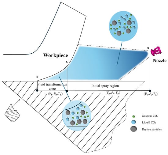
Figure 1.
The fluid motion process of the front cutting surface during scCO2-MQL machining.
2.1.1. Initial Injection Zone Dynamic Model
Upon nozzle ejection, the scCO2 underwent rapid pressure reduction from 8 MPa to atmospheric pressure, inducing a temperature decline through the Joule-Thomson effect and facilitating the formation of dry ice with characteristic under-expanded flow properties.
As shown in Figure 2, the jet core region from the nozzle exit to the Mach disk exhibits extremely high velocity and low pressure. Temperatures near the Mach disk dropped to −78 °C due to rapid expansion. Beyond the Mach disk, the flow velocity decreased to sonic speed, and the pressure equilibrated with ambient conditions. Following the transition segment, the flow completely transforms into one-dimensional submerged jet motion [].
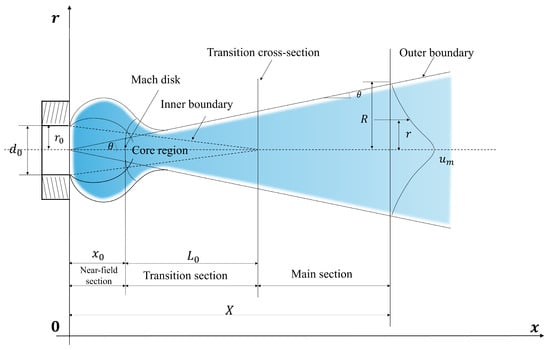
Figure 2.
Macro structure diagram of jet flow.
When the pressure ratio between the nozzle exit and ambient conditions exceeded the critical value, a Mach disk structure developed within the jet. The axial position of the Mach disk was determined as follows []:
where
is the axial distance from the nozzle exit to the Mach disk
is the nozzle exit diameter (m);
represents the stagnation pressure of the jet at the nozzle exit, which is the pressure of the fluid if it were brought to rest isentropically; and
is the ambient pressure into which the jet is discharged.
Based on the momentum conservation principles and accounting for the Mach disk influence, the transition segment length can be expressed as
where
represents the transition segment length,
denotes the nozzle radius,
is the Mach number,
represents the momentum correction coefficient (reflecting velocity distribution non-uniformity,
for uniform flow), and x0 indicates the Mach disk position.
Within the main segment, the relationship between the centerline velocity and axial distance can be expressed as
where
represents the centerline velocity
, c denotes the sonic velocity
, and
indicates the axial distance from the nozzle
. This Equation (3) demonstrates that the centerline velocity is inversely proportional to the distance, which directly influences the spatial distribution of the cooling efficiency.
2.1.2. Initial Injection Zone Thermodynamic Analysis
Let the temperature at the jet nozzle cross-section be denoted as
, the ambient temperature as
, the centerline temperature as
, and the temperature at any point on the selected cross-section as
. The corresponding concentrations are denoted as
, and
respectively. Experimental measurements of jet cross-sections revealed the following correlations among the temperature, concentration, and velocity distributions []:
This relationship indicates that the temperature gradient distribution exhibits a nonlinear correlation with the velocity gradient. At the jet boundary
, the temperature approaches the ambient temperature, at the centerline
, the temperature reaches its local minimum value
.
A conservation-based integral model was established to quantify the thermal energy transfer under scCO2-MQL conditions.
Building upon Equation (5), and innovatively extended Abramovich’s centerline model to account for multiphase-jet characteristics. The present study incorporated the enhanced convective cooling contributed by CO2 dry ice particles. The resulting predictive equation for the centerline temperature drop is
where
represents the influence coefficient of carbon dioxide dry ice particles,
, with specific values influenced by factors such as the carbon dioxide dry ice particle concentration.
Similarly, for the lubricating oil mist droplet concentration variation, we derived
However, to reflect the continuous sublimation and phase loss of CO2 particles during transport, an additional correction factor
was introduced into the concentration field as follows:
This multiparameter model provides a novel framework for predicting the spatiotemporal evolution of multiphase jets in scCO2-MQL environments, laying a theoretical foundation for optimising cooling and lubrication strategies in high-performance machining.
2.1.3. Fluid Transformation Zone Dynamic Model
The flow characteristics from the initial injection zone reached the entrance of the fluid transformation zone after passing through the Mach disk structure and transition segment. At position
, following the supercritical phase transformation and temperature plunge induced by the Joule-Thomson effect, the fluid transitioned to near-wall flow based on boundary layer theory.
Equation (9) establishes the velocity connection between the two regions, ensuring the continuity of flow characteristics at the transition position. This indicates that the velocity at the entrance of the fluid transformation zone equals the centerline velocity at the end of the initial injection zone (the endpoint of the transition segment).
The Navier–Stokes equations for this phase of fluid flow can be expressed as [].
The fluid motion analysis near the tool rake face in the second stage is illustrated in Figure 3, where fluid moves from right to left along the rake face with velocity
, forming the boundary layer as shown. Setting
,
, the boundary layer equations become:
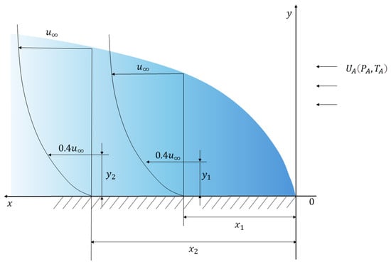
Figure 3.
Boundary layer of a flat plate.
By introducing the dimensionless parameter
, Equation (11) is transformed into a third-order nonlinear ordinary differential equation as follows:
With boundary conditions:
at
,
as
.
Although this equation lacks an analytical solution, it can be approximated using numerical methods. By further introducing the boundary layer momentum integral relationship, we derived the relationship between the boundary layer thickness
and
:
where
represents the Reynolds number with
as the characteristic length, this relationship enables the calculation of the boundary layer thickness at any position on the rake face, providing an accurate understanding of the fluid movement across its surface and establishing a theoretical foundation for understanding the fluid behaviour on the tool surface.
2.1.4. Fluid Transformation Zone Thermodynamic Analysis
The entrance of the fluid transformation zone exhibited a low temperature, whereas the rake face and chips reached high temperatures owing to severe deformation during cutting. High-speed, low-temperature fluids undergo intense convective heat transfer in the transformation zone. Building on the movement boundary layer, thermal boundary layer equations were established to analyse the convective heat transfer during this phase.
For a two-dimensional steady boundary layer flow without internal heat generation, the governing equations are [].
where
and
represent velocity components in
and
directions, respectively,
denotes pressure,
represents kinematic viscosity, α denotes thermal diffusivity.
In boundary layer theory, the quantitative relationship between the flow and thermal boundary layer thicknesses is
2.2. Heat Transfer Coefficient Calculation
During the machining of γ-TiAl alloys with scCO2-MQL, the cooling effectiveness primarily depends on the convective heat transfer between the fluid and tool/workpiece surfaces. Based on the classical heat transfer theory, the local convective heat transfer coefficients can be calculated using the Nusselt number.
2.2.1. Basic Heat Transfer Coefficient
To rigorously validate the proposed modified model, a conventional heat transfer coefficient derived from the classical Chilton-Colburn analogy for flat-plate convection is established as a baseline. It provides a standard, universally recognized reference for comparison.
For laminar forced convection over a flat plate, the local convective heat transfer coefficient can be expressed as
where
represents the Reynolds number with
as the characteristic length, an
represents the Prandtl number. Rearranging Equation (16):
The local Nusselt number was obtained as follows:
Through the Chilton-Colburn analogy, for external isothermal flat plate flow with
, setting the critical Reynolds number
, we obtain:
where
represents the Reynolds number with the plate’s total length
as the characteristic length. The average surface heat transfer coefficient
for the entire plate is calculated as follows:
2.2.2. Modified Heat Transfer Coefficient
Conventional heat transfer coefficients derived from the flat-plate turbulent boundary layer theory exhibit limited accuracy in characterising scCO2 jet cooling phenomena because these models fail to account for the distinctive flow characteristics inherent to supercritical fluid jets. Conventional correlations fail to account for critical phenomena that significantly affect heat transfer performance: (1) Mach disk formation effects that enhance local heat transfer intensity, (2) non-uniform radial velocity distributions that modify convective coefficients, and (3) CO2 phase transitions involving dry ice formation and sublimation. The synergistic interactions between these mechanisms generate enhanced cooling effects that conventional single-phase convection correlations cannot adequately capture. Consequently, modified heat transfer coefficients that incorporate these scCO2-specific mechanisms are essential for precise thermal analysis in supercritical fluid machining applications.
Following a systematic investigation of jet fluid dynamics and heat transfer mechanisms, this study established a modified heat transfer coefficient calculation methodology.
This approach adopts conventional turbulent heat transfer relationships as the foundational framework, while introducing two critical modification functions,
and
, to characterise jet dynamics and thermal properties. The Mach disk correction factor
quantifies the enhancement effect on heat transfer efficiency as follows:
This function characterises the modulation effect of the Mach disk structure on the enhanced heat transfer of the jet. When fluid resides within the Mach disk region
, intense pressure and velocity gradients generate strong turbulent fluctuations and local vortical structures, significantly enhancing convective heat transfer efficiency. As the distance from the Mach disk position increased, this enhancement effect gradually diminished, when
, reflecting the conventional heat transfer characteristics of far-field jets.
To precisely characterise the modulating effect of radial velocity distribution on heat transfer coefficients, the velocity distribution influence function
is introduced:
This function is constructed based on the radial velocity distribution characteristics in the jet main segment, where the cross-sectional radius
. The function quantifies the influence of the radial velocity distribution on the local heat transfer coefficients with a form isomorphic to the velocity distribution equation, ensuring self-consistency in the physical meaning.
Integrating these factors, the final optimized heat transfer coefficient expression is as follows:
The modified heat transfer coefficient comprehensively accounts for (1) fluid dynamic effects through Mach disk and velocity distribution corrections, (2) phase-change enhancement via dry ice particle formation, and (3) temperature gradient influences, establishing a robust theoretical framework for scCO2-MQL thermal modeling. In this formulation, λ represents the thermal conductivity of scCO2, l denotes characteristic length, collectively constituting the dimensional basis of the heat transfer coefficient; the dry ice particle influence coefficient quantifies the heat transfer enhancement effect through latent heat of phase change and solid-gas two-phase flow, essentially reflecting the contribution of supercritical-to-solid phase transformation to heat absorption, the temperature ratio correction term
reflects the contribution of temperature differential between workpiece surface and fluid to heat transfer enhancement.
3. Simulation and Experimental Setup
3.1. Simulation Method
A two-dimensional thermomechanically coupled finite element model was developed using ABAQUS 2024 to simulate the γ-TiAl cutting process. An explicit dynamic solver was employed to handle the highly nonlinear characteristics of machining, including large deformations, progressive material failure, and complex tool-workpiece contact interactions. The solution employed adaptive time stepping with automatic time increment control, while the mass-scaling factor was constrained to be below five to maintain quasi-static conditions and ensure solution stability. Element distortion during chip formation was addressed using the Johnson-Cook damage criterion coupled with element deletion techniques. Elements exceeding the critical damage parameter were automatically removed to simulate natural chip separation while maintaining computational stability. The plastic behaviour of the γ-TiAl alloy was characterised using the Johnson-Cook constitutive model, which effectively accommodates the high strain rates and elevated temperatures encountered during cutting operations.
A 2D turning simulation model for the γ-TiAl alloy was established, as shown in Figure 4. The thermophysical and mechanical properties of the γ-TiAl alloy used in the simulations are listed in Table 1.
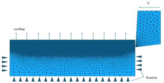
Figure 4.
Geometric model of 2D cutting.

Table 1.
Mechanical properties of γ-TiAl.
The Johnson-Cook constitutive equation model for γ-TiAl alloy is []:
The mechanical boundary conditions were configured as follows: the bottom edge of the workpiece was subjected to fully constrained conditions, restricting all degrees of freedom; the lateral boundaries of the workpiece were assigned symmetric constraints, limiting only the vertical displacement components; and the top surface of the workpiece remained a free boundary. Tool motion was implemented by applying constant velocity boundary conditions at the reference point, with cutting velocities set at four discrete levels corresponding to the experimental conditions: 15, 25, 35, and 45 m/min. The thermal boundary condition specification proved to be considerably more intricate, necessitating an accurate representation of the scCO2-MQL cooling phenomenon. The initial temperature of the workpiece was uniformly prescribed at 20 °C.
The thermophysical parameters of scCO2 at 50 °C under 8 MPa pressure (supercritical state) were obtained as follows (Table 2).

Table 2.
Thermophysical parameters of scCO2 (at 8 MPa pressure).
Using the parameters (nozzle diameter
, nozzle velocity
, and surface distance
), the heat transfer coefficients were calculated according to the theoretical models developed in Section 2. The calculation results are presented in Table 3.

Table 3.
Heat transfer coefficient calculation results.
The calculated modified heat transfer coefficient (h∗m) was integrated into the ABAQUS finite element model by applying a *FILM boundary condition to the workpiece surfaces exposed to the coolant jet.
3.2. Experimental Configuration
To evaluate the reliability and accuracy of the established numerical model and simulation method, comparative analyses of the experimental and simulation results were conducted to validate the predictive precision of the model developed in this study.
The experimental material consisted of γ-TiAl alloy bars with dimensions of
65.5 mm × 196 mm. The experimental setup is illustrated in Figure 5. A CKA6150 CNC lathe was selected, as shown in Figure 5b, which can perform complex, high-precision external cylindrical and face machining operations. The experimental site is shown in Figure 5c. Cemented carbide inserts (Mitsubishi turning insert CNMG120408-MJ, cemented carbide grade RT9010, uncoated, hardness HRA91.8) were selected. The scCO2-MQL equipment used was the Cry0lube-iOOW system manufactured by Dongguan Amolin Mechanical Manufacturing Technology Co., Ltd. (Dongguan, China), as shown in Figure 5a,b. This system operates based on the Joule-Thomson effect, where high-pressure CO2 (7.5–8.5 MPa) undergoes rapid expansion upon exiting the nozzle. This expansion creates a three-phase jet of gaseous CO2, solid dry ice particles, and atomized oil droplets, which provides simultaneous cryogenic cooling and lubrication to the cutting zone.

Figure 5.
Experimental equipment.
The cutting parameters are listed in Table 4.

Table 4.
Cutting parameters.
The system parameters are shown in Table 5.

Table 5.
Parameters of the supercritical carbon dioxide micro lubrication system.
A single-factor experimental design was employed, with cutting speed as the primary variable, while the feed rate (0.15 mm/rev) and cutting depth (1 mm) were held constant. Each experimental condition was repeated three times to ensure measurement reliability, and the arithmetic mean of the three measurements was calculated as the final result for subsequent analysis.
4. Results and Discussion
4.1. Model Validation and Accuracy Assessment
Model reliability was assessed using two error metrics: absolute error and relative error. The predictive performances of the conventional and modified heat-transfer coefficient models were evaluated through a systematic comparison with experimental data under varying cutting conditions.
Figure 6 shows that the modified heat transfer coefficient model demonstrates superior predictive accuracy compared with the conventional model. At a low cutting speed (15 m/min), the absolute error decreased from 12 N (conventional model) to 10 N (modified model), representing an improvement of 16.7%. As the cutting speed increased to 45 m/min, the errors of both models approached 2N. This indicates that in high-speed cutting regions, the thermal effects on the material behaviour exceed the lubrication factors, which is consistent with the metal thermal softening theory.
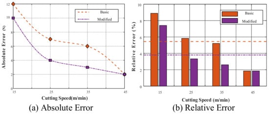
Figure 6.
Error analysis of cutting forces.
A relative error analysis further confirmed the advantages of this modified model. The modified heat transfer coefficient model exhibited an average relative error of 8.1%, representing a 21.8% reduction compared to the basic model’s 10.3%. In particular, under medium-speed cutting conditions (25 m/min), the error reduction reached 42.9%, confirming that the precise characterisation of the heat transfer coefficients within this velocity range has a decisive impact on cutting force prediction.
Figure 6 presents the comparative results of the temperature prediction performance. As shown in Figure 6a, the modified heat transfer coefficient demonstrated superior temperature prediction accuracy across the entire velocity range. At a cutting speed of 15 m/min, the temperature deviation between the basic model and the experimental value was 28 °C, whereas the modified model reduced this to 20 °C. As the cutting speed increased to 45 m/min, the basic model error expanded to 71 °C. In contrast, the modified model showed only a 16 °C deviation, demonstrating significant advantages and indicating that the modified heat-transfer coefficient more accurately captures the complex heat-transfer behaviour in high-speed cutting environments.
The temperature-relative error analysis (Figure 7b) demonstrates that the modified model achieved an average relative error of 8.5% across various cutting speeds, which is a 37.3% reduction compared with the basic model of 13.6%. In particular, under high-speed cutting conditions (45 m/min), the modified model exhibited the most significant improvement in prediction accuracy, with the relative error decreasing from 14.1% to 3.2%, representing a 77.5% reduction. This confirms that the modified heat transfer coefficient more precisely characterises the enhanced convective heat transfer mechanism between scCO2 and the workpiece surfaces under high-speed cutting conditions.
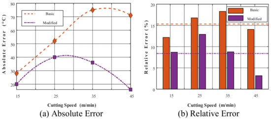
Figure 7.
Error analysis of cutting temperatures.
The comprehensive error analysis results for the cutting force and temperature fields indicate that the modified heat transfer coefficient demonstrates superior predictive performance compared to the basic heat transfer coefficient across the entire velocity range. This result validates the rationality of the modified heat transfer coefficient proposed in this study for describing scCO2-MQL cooling mechanisms, providing a reliable theoretical foundation for an in-depth analysis of the mechanical and thermodynamic characteristics of γ-TiAl alloy cutting under scCO2-MQL conditions.
4.2. Cutting Force and Temperature Evolution Characteristics
Figure 8 compares the experimental and simulated cutting forces for γ-TiAl machining under scCO2-MQL conditions using the modified heat transfer coefficient model. The results showed that the cutting force decreased with increasing cutting speed, dropping from 135 N at 15 m/min to 109 N at 45 m/min. This trend results from two competing mechanisms: (1) increased cutting speed generates higher cutting zone temperatures, inducing thermal softening that reduces material strength, and (2) efficient scCO2-MQL cooling suppresses excessive temperature increases while reducing tool-chip friction coefficients. Under scCO2-MQL conditions, the efficient cooling action effectively suppressed thermal softening phenomena, maintaining higher material strength levels while simultaneously reducing the friction coefficient at the tool-chip interface. The combined action of these mechanisms resulted in an overall decreasing trend in the cutting forces.
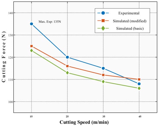
Figure 8.
Comparison of cutting forces.
As shown in Figure 9, the cutting temperature exhibited a nonlinear growth relationship with the cutting speed, increasing significantly from 235 °C at 15 m/min to 505 °C at 45 m/min. The modified heat transfer coefficient model maintained high consistency with the experimental data across the entire velocity range, with an average prediction deviation of only 4.6%. In contrast, the basic heat transfer coefficient model generally predicted higher temperatures, particularly in high-speed regions, with maximum temperature predictions reaching 579 °C, exceeding the experimental values by over 14.1%.
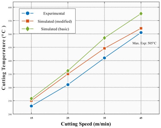
Figure 9.
Comparison of cutting temperatures.
The analysis indicates that the modified heat transfer coefficient significantly improves the accuracy of temperature field predictions by precisely capturing the phase-change heat transfer characteristics of the scCO2 fluid and the flow field distribution in the cutting zone. Particularly under high-speed cutting conditions, the basic model fails to accurately characterise the complex convective heat transfer process formed by scCO2 jet impingement cooling. In contrast, the modified model effectively resolves this issue, reducing the temperature prediction errors.
4.3. Multi-Field Distribution Characteristics in Cutting Zone
Figure 10a reveals a highly non-uniform stress distribution in γ-TiAl under scCO2-MQL conditions. The maximum equivalent stress concentrations (1106–1306 MPa) occurred within the primary shear zone, forming distinct shear bands characterised by intense plastic deformation. The stress field displayed distinct gradient characteristics along the cutting direction, gradually decreasing from the cutting edge region toward the chip-free surface, with a range of 114 to 334 MPa. A secondary high-stress zone (775–885 MPa) formed at the tool-chip interface region, with a distribution directly related to the tool friction effects.

Figure 10.
Stress field, temperature field, and equivalent plastic strain field.
As the cutting speed increased, the concentration of the high-stress zone intensified, and the stress gradients became steeper. When the cutting speed increased from 15 m/min to 45 m/min, the stress field concentration became more pronounced despite an overall decrease in the main cutting force, providing the fundamental mechanical conditions for the subsequent periodic formation of serrated chips.
As illustrated in Figure 10b, the temperature field in the cutting zone exhibited distinct gradient distribution characteristics. The highest temperature zone is primarily located at the intersection of the tool-chip interface and primary deformation zone, with temperature contours displaying characteristic “arc-shaped” distributions in the cutting region. The temperature field formed clearly demarcated gradients from the tool rake face toward the chip-free surface, with chip root region temperatures maintained within the 314–363 °C range. Temperature gradients significantly decreased with distance from the cutting zone.
The efficient cooling effect of scCO2-MQL creates distinct layered temperature gradient characteristics, particularly in the critical regions of chip formation, where the temperature gradients substantially exceed those under conventional cooling conditions. This steep temperature gradient distribution creates the necessary thermodynamic conditions for shear-band localisation, which is a crucial factor in serrated chip formation.
As shown in Figure 10c, the equivalent plastic strain field exhibited distinct layered characteristics, with maximum values concentrated in the shear deformation zone, displaying a gradient reduction trend along the cutting direction. As the cutting speed increased, the distribution range of the equivalent plastic strain in the deformation zone became more concentrated, with slightly reduced maximum values, which were highly consistent with the trends in stress concentration zone variation.
This distribution characteristic of the plastic strain field is closely related to the nonlinear cooling effect of scCO2, which forms a synergistic coupling mechanism among the stress, temperature, and plastic strain fields. As the cutting speed increased, the scCO2 cooling efficiency improved, which elevated the material strength and caused more localized and non-uniform deformation, providing a microstructural deformation foundation for serrated chip formation.
4.4. Serrated Chip Formation Phenomenon Analysis
Figure 11 illustrates the temporal evolution of the chip formation during γ-TiAl machining under scCO2-MQL conditions. Finite element analysis captures the characteristic features of serrated chip formation, including periodic stress concentrations, localised temperature increases, and progressive shear band development. The simulation demonstrated localised stress concentrations exceeding 1200 MPa in discrete regions, accompanied by corresponding temperature elevations of up to 521 °C.

Figure 11.
Serrated chip formation process.
Microstructural examination of the chip specimens revealed surface features consistent with the computational predictions. As shown in Figure 12, the chip-free surface exhibited alternating regions with different deformation characteristics, with dimple structures concentrated in areas corresponding to the simulated high-temperature zones. These morphological features aligned with the stress and strain distributions predicted by finite element analysis.
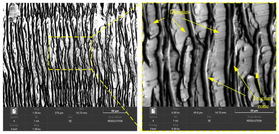
Figure 12.
Chip-free surface.
The scCO2-MQL cooling system creates non-uniform thermal boundary conditions that influence the material flow behaviour. The temperature gradients established by the cooling system corresponded to the spatial variations in the stress and strain distributions observed in the simulation results. Concurrently, the reduced friction coefficient under cooling conditions alters the stress transmission mechanisms within the cutting zone, optimising the stress distribution while enhancing the concentration effects at predetermined locations, thereby facilitating controlled serrated chip formation.
Computational and experimental analyses provided a comprehensive characterisation of the chip formation behaviour of γ-TiAl alloys under scCO2-MQL conditions. The modified heat transfer coefficient model enables more accurate predictions of temperature distributions and stress fields, contributing to an improved understanding of thermal management in machining difficult-to-cut materials.
5. Conclusions
The present study investigates the heat transfer mechanisms, cutting force characteristics, temperature field distributions, and serrated chip formation phenomena in γ-TiAl machining under scCO2-MQL conditions. This is achieved through the development and validation of a modified heat transfer coefficient model incorporating Mach disk correction factors and radial velocity distribution functions. The following conclusions were drawn from this study:
- A modified heat transfer coefficient model was developed by incorporating two correction factors: (quantifying Mach disk enhancement effects) and (accounting for radial velocity distribution).
- Model validation was conducted through comparative analysis of experimental and simulation results for cutting forces and temperature fields. The modified model exhibited superior predictive performance with 21.8% and 37.3% reductions in average relative error for cutting force and temperature predictions, respectively, compared to the basic model. The predicted thermal and stress distributions demonstrated high consistency with experimental measurements.
- Through comparative simulations between the modified model and basic models, it was found that the modified heat transfer coefficient model demonstrated significantly enhanced consistency between the simulated serrated chip morphology and experimental observations.
The present study establishes a validated thermal modeling framework for the scCO2-MQL machining of γ-TiAl alloys. The improved prediction accuracy of the modified heat transfer coefficient model enables more reliable process planning and thermal management in production environments. Future investigations should explore multi-parameter optimization, including feed rate variations and cutting depth effects, to establish comprehensive process maps for industrial-scale applications and quantify the economic viability of scCO2-MQL technology for γ-TiAl machining.
Author Contributions
Conceptualization, L.S. and X.Z.; methodology, L.S. and X.Z.; software, X.Z. and L.C.; validation, X.Z. and H.C.; formal analysis, L.S. and X.Z.; investigation, L.S. and X.Z.; resources, L.S.; data curation, X.Z.; writing—original draft preparation, L.S.; writing—review and editing, L.S.; visualization, X.Z. and L.C.; supervision, E.L.; project administration, L.S.; funding acquisition, L.S. and E.L. All authors have read and agreed to the published version of the manuscript.
Funding
This research was funded by National Natural Science Foundation of China Project: Research on the Synergistic Milling Technology of Supercritical Carbon Dioxide—Minimum Quantity Lubrication—Ultrasonic Vibration for Aviation TC11 Titanium Alloy, grant number 52265059; Gansu Provincial Natural Science Foundation: Research on the Mechanism of Synergistic Milling of Supercritical Carbon Dioxide—Minimum Quantity Lubrication—Ultrasonic Vibration, grant number 22JR11RE194.
Institutional Review Board Statement
Not applicable.
Informed Consent Statement
Not applicable.
Data Availability Statement
The raw/processed data required to reproduce these findings can be obtained from the corresponding author (Limin Shi slm@tsnu.edu.cn) upon reasonable request.
Conflicts of Interest
The authors declare no conflicts of interest.
References
- Cheng, T.T.; Willis, M.R.; Jones, I.P. Effects of significant alloying additions on the microstructure and mechanical properties of γ-TiAl. Intermetallics 1999, 7, 89–99. [Google Scholar] [CrossRef]
- Zhang, C.; Wang, W.; Li, H. Tool wear prediction method based on symmetrized dot pattern and multi-covariance Gaussian process regression. Measurement 2021, 189, 110466. [Google Scholar] [CrossRef]
- Xu, R.; Li, M.; Zhao, Y. A review of microstructure control and mechanical performance optimization of γ-TiAl alloys. J. Alloys Compd. 2023, 932, 167611. [Google Scholar] [CrossRef]
- Ye, Y.; Wang, J. An Overview on Application Status and Processing Technology Development of Titanium Alloy. Mater. Rev. 2012, 26, 360–363. [Google Scholar]
- Zhou, L.; Yao, L.; Chen, Y.; Jiang, L.; Wang, C. Supercritical-CO2 Minimum Quantity Lubrication Technology for Hard-to-cut Materials. Tool Eng. 2019, 53, 3–6. [Google Scholar]
- Pimenov, D.Y.; da Silva, L.R.R.; Machado, A.R.; Franca, P.H.P.; Pintaude, G.; Unune, D.R.; Kuntoğlu, M.; Krolczyk, G.M. A comprehensive review of machinability of difficult-to-machine alloys with advanced lubricating and cooling techniques. Tribol. Int. 2024, 196, 109677. [Google Scholar] [CrossRef]
- Lewis, J.; Argyropoulos, J.N.; Nielson, K.A. Supercritical carbon dioxide spray systems. Met. Finish. 2000, 98, 254–262. [Google Scholar] [CrossRef]
- Pušavec, F.; Kopač, J.; Stoic, A.; Balic, J.; Sokovic, M. Sustainability Assessment: Cryogenic Machining of Inconel 718. Stroj. Vestn.—J. Mech. Eng. 2011, 57, 637–647. [Google Scholar] [CrossRef]
- Pereira, O.; Celaya, A.; Urbikaín, G.; Rodríguez, A.; Fernández-Valdivielso, A.; de Lacalle, L.N.L. CO2 cryogenic milling of Inconel 718: Cutting forces and tool wear. J. Mater. Res. Technol. 2020, 9, 8459–8468. [Google Scholar] [CrossRef]
- Supekar, S.D.; Clarens, A.F.; Stephenson, D.A.; Skerlos, S.J. Performance of supercritical carbon dioxide sprays as coolants and lubricants in representative metalworking operations. J. Mater. Process. Technol. 2012, 212, 2652–2658. [Google Scholar] [CrossRef]
- Rahim, E.A.; Rahim, A.A.; Ibrahim, M.R.; Mohid, Z. Experimental Investigation of Supercritical Carbon Dioxide (scCO2) Performance as a Sustainable Cooling Technique. Procedia Cirp 2016, 40, 637–641. [Google Scholar] [CrossRef]
- Khosravi, J.; Azarhoushang, B.; Barmouz, M.; Bösinger, R.; Zahedi, A. High-speed milling of Ti6Al4V under a supercritical CO2 + MQL hybrid cooling system. J. Manuf. Process. 2022, 82, 1–14. [Google Scholar] [CrossRef]
- Proud, L.; Tapoglou, N.; Wika, K.K.; Taylor, C.M.; Slatter, T. Role of CO2 cooling strategies in managing tool wear during the shoulder milling of grade 2 commercially pure titanium. Wear 2023, 524–525, 204798. [Google Scholar] [CrossRef]
- Zhu, L.; Wang, Y.; Nie, S.; Huang, H.; Liu, Z. Thermal Equilibrium Research of Supercritical CO2 Assisted Cutting Process Based on Mass Flow Optimization. J. Mech. Eng. 2024, 60, 367–376. [Google Scholar]
- Zhu, L.; Wang, Y.; Zhang, X.; Bao, H.; Qing, Z.; Peng, K.; Liu, Z.; Huang, H. Thermal equilibrium modeling of cutting zone cooled by supercritical CO2: A case study on Ti-6Al-4V validated with experimental data. J. Manuf. Process. 2023, 98, 54–66. [Google Scholar] [CrossRef]
- Shi, L.; Wang, T.; Liu, E.; Wang, R. Lubrication Mechanism of scCO2-MQL in the Assisted Machining of Titanium Alloys. Machines 2023, 11, 291. [Google Scholar] [CrossRef]
- Proud, L.; Roberts, P.; Xu, N.; Wika, K.K.; Morina, A.; Taylor, C.M. The tool wear and productivity impact of CO2 and emulsion-based cooling when milling diverse titanium alloys. Wear 2025, 570, 206031. [Google Scholar] [CrossRef]
- Luo, T. Fluid Mechanics; China Machine Press: Beijing, China, 2003. [Google Scholar]
- Crist, S.; Glass, D.; Sherman, P. Study of the highly underexpanded sonic jet. AIAA J. 1966, 4, 68–71. [Google Scholar] [CrossRef]
- Zhang, Z.; Dong, Z. Viscous Fluid Mechanics; Tsinghua University Press: Beijing, China, 2011. [Google Scholar]
- Yang, S.; Tao, W. Heat Transfer; Higher Education Press: Beijing, China, 2006. [Google Scholar]
- Wang, X.; Qiu, W.; Niu, J.; Liu, G.; Fu, X.; Guo, P.; Qiao, Y. Experimental and simulation investigation of cutting temperatures in cryogenic machining of titanium aluminide alloys. J. Mech. Eng. 2024, 60, 318–331. [Google Scholar]
Disclaimer/Publisher’s Note: The statements, opinions and data contained in all publications are solely those of the individual author(s) and contributor(s) and not of MDPI and/or the editor(s). MDPI and/or the editor(s) disclaim responsibility for any injury to people or property resulting from any ideas, methods, instructions or products referred to in the content. |
© 2025 by the authors. Licensee MDPI, Basel, Switzerland. This article is an open access article distributed under the terms and conditions of the Creative Commons Attribution (CC BY) license (https://creativecommons.org/licenses/by/4.0/).