
Extreme High-Speed DED of AISI M2 Steel for Coating Application and Additive Manufacturing


Abstract
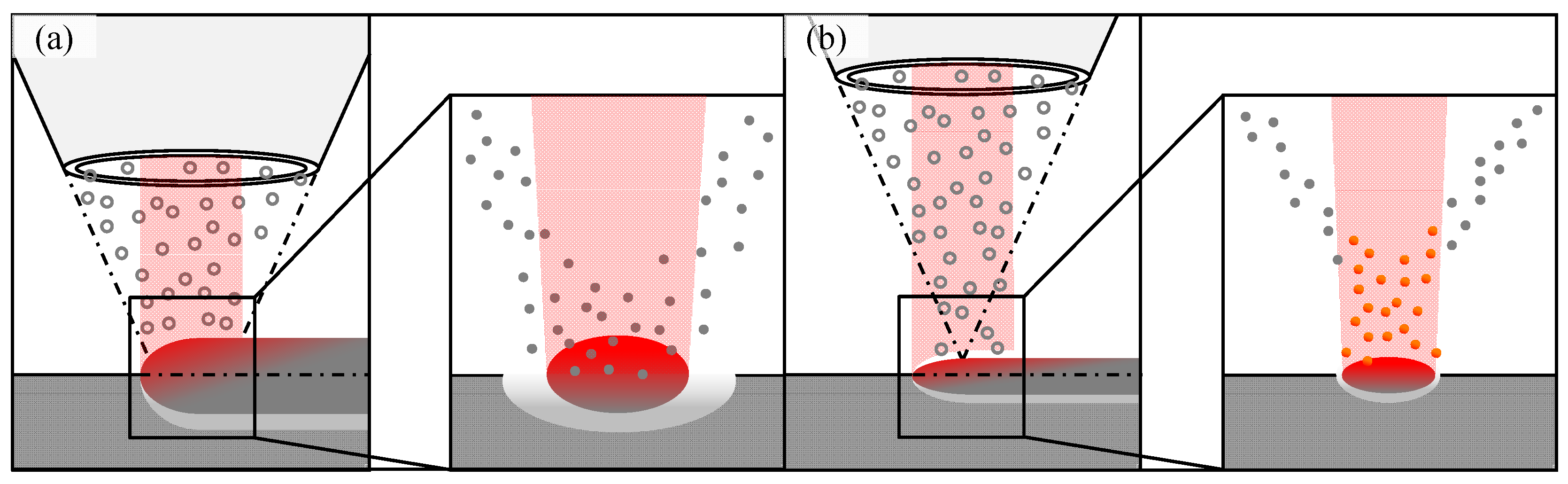
1. Introduction and State-of-the-Art
2. Materials and Methods
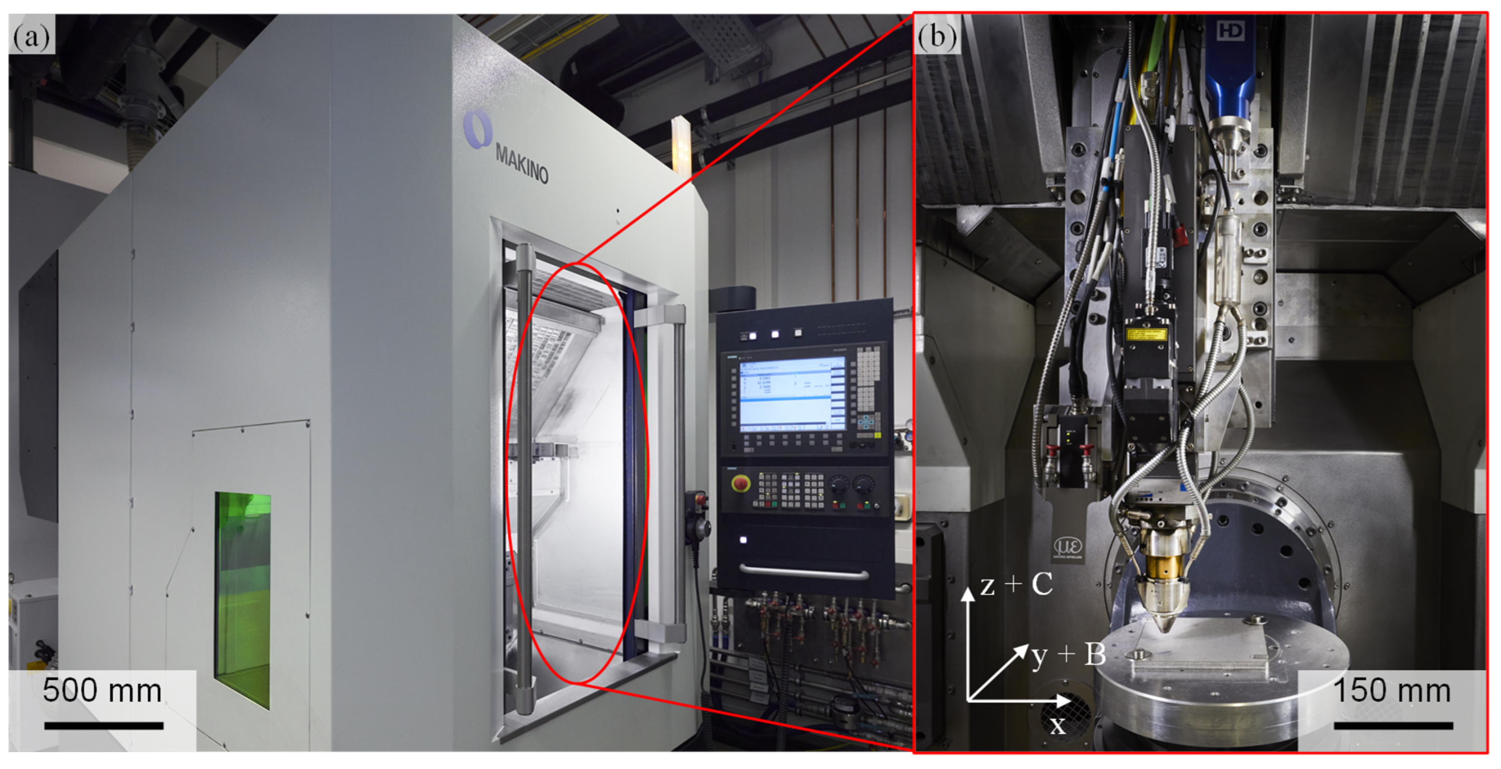
2.1. System Technology
2.2. Materials
2.3. Methods
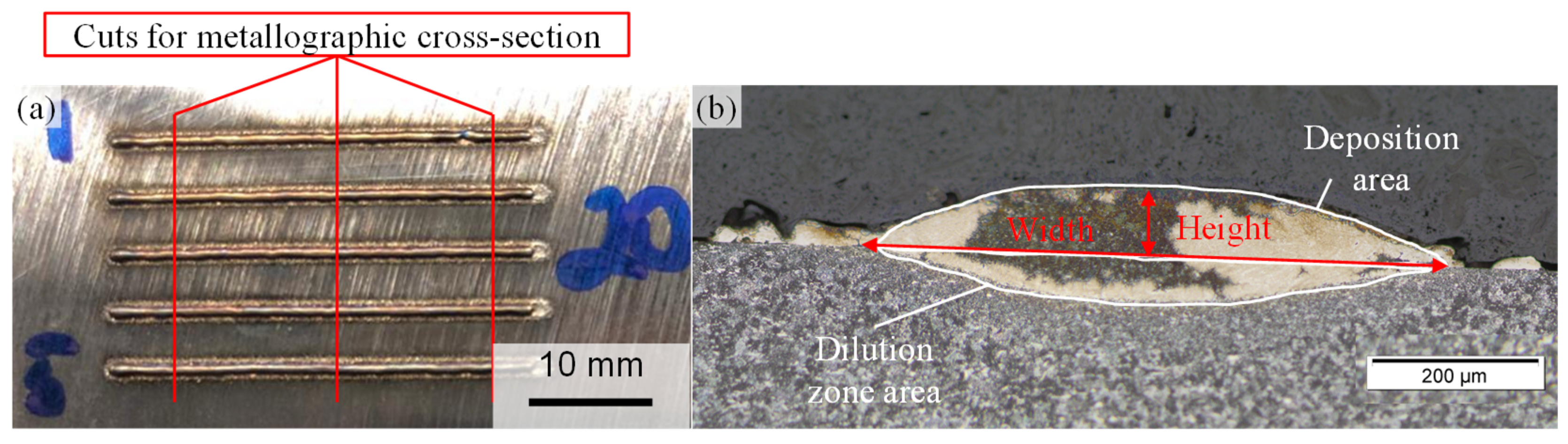
2.3.1. Single-Track Evaluation
- -
- Weld bead width;
- -
- Weld bead height;
- -
- Deposition area;
- -
- Dilution zone area.
- -
- No bonding defects;
- ○
- Depth of dilution zone: 20–50 µm;
- -
- No pores;
- -
- No crack formation;
- -
- Set powder mass flow:
- ○
- High productivity: 1.9 kg/h;
- ○
- Low heat input: 0.4 kg/h.
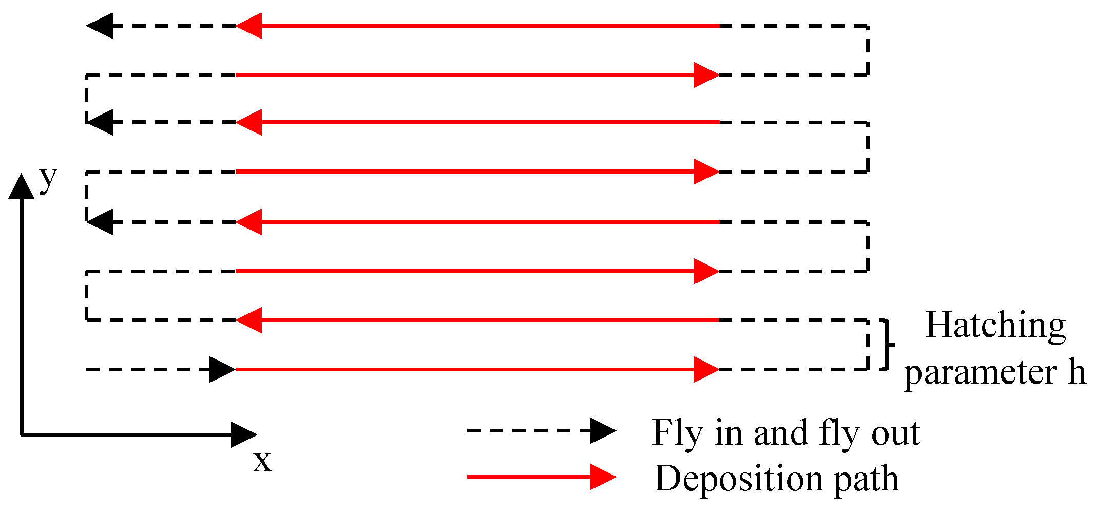
2.3.2. Coating Deposition
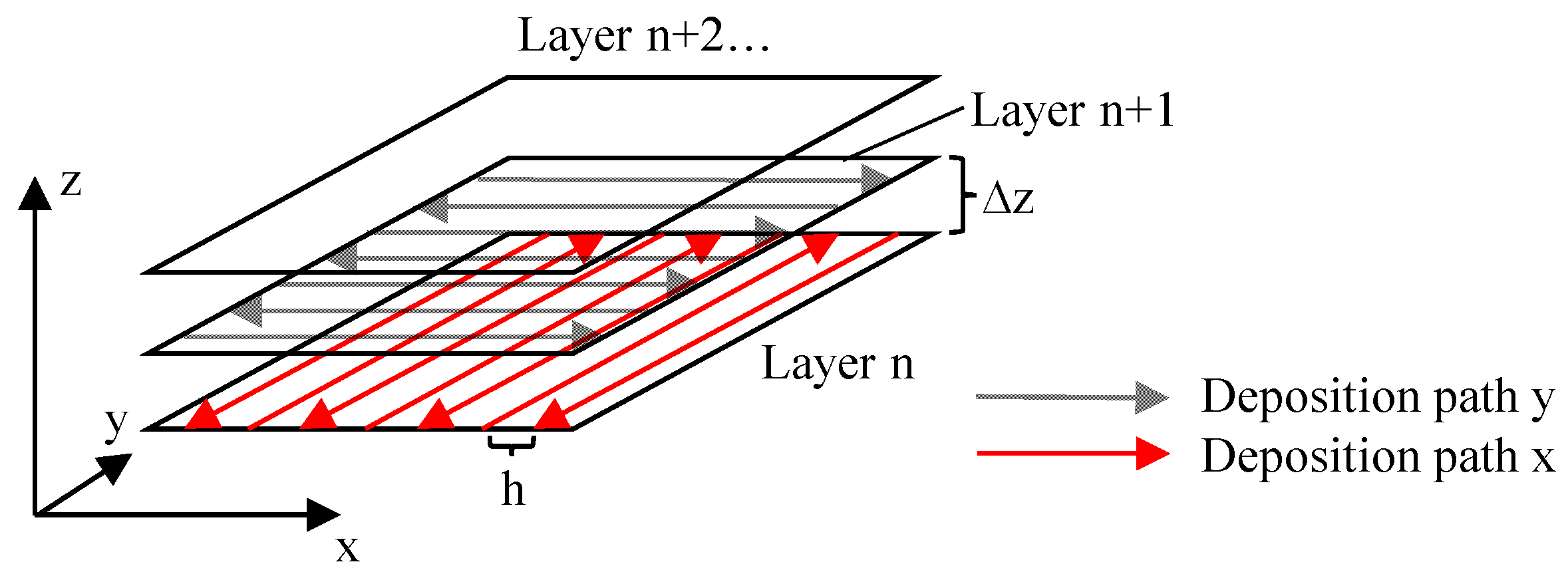
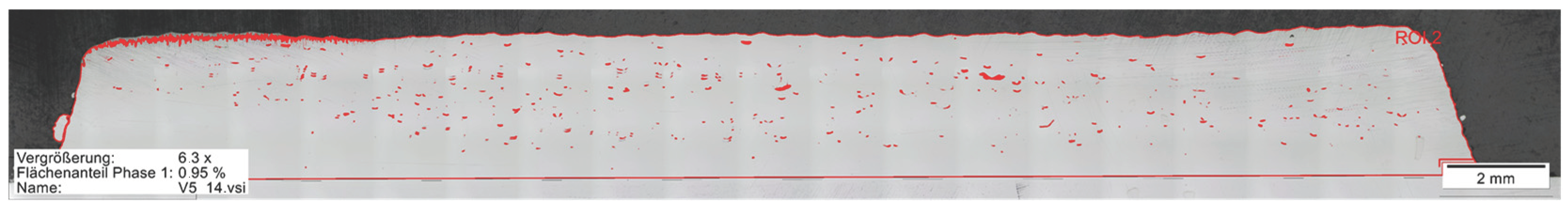
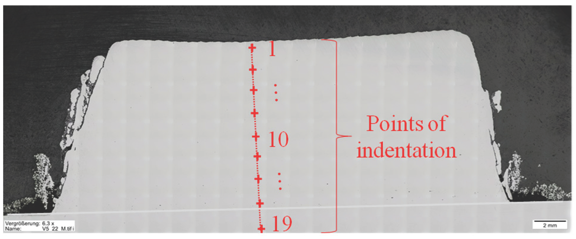
2.3.3. Volume
3. Results and Discussion
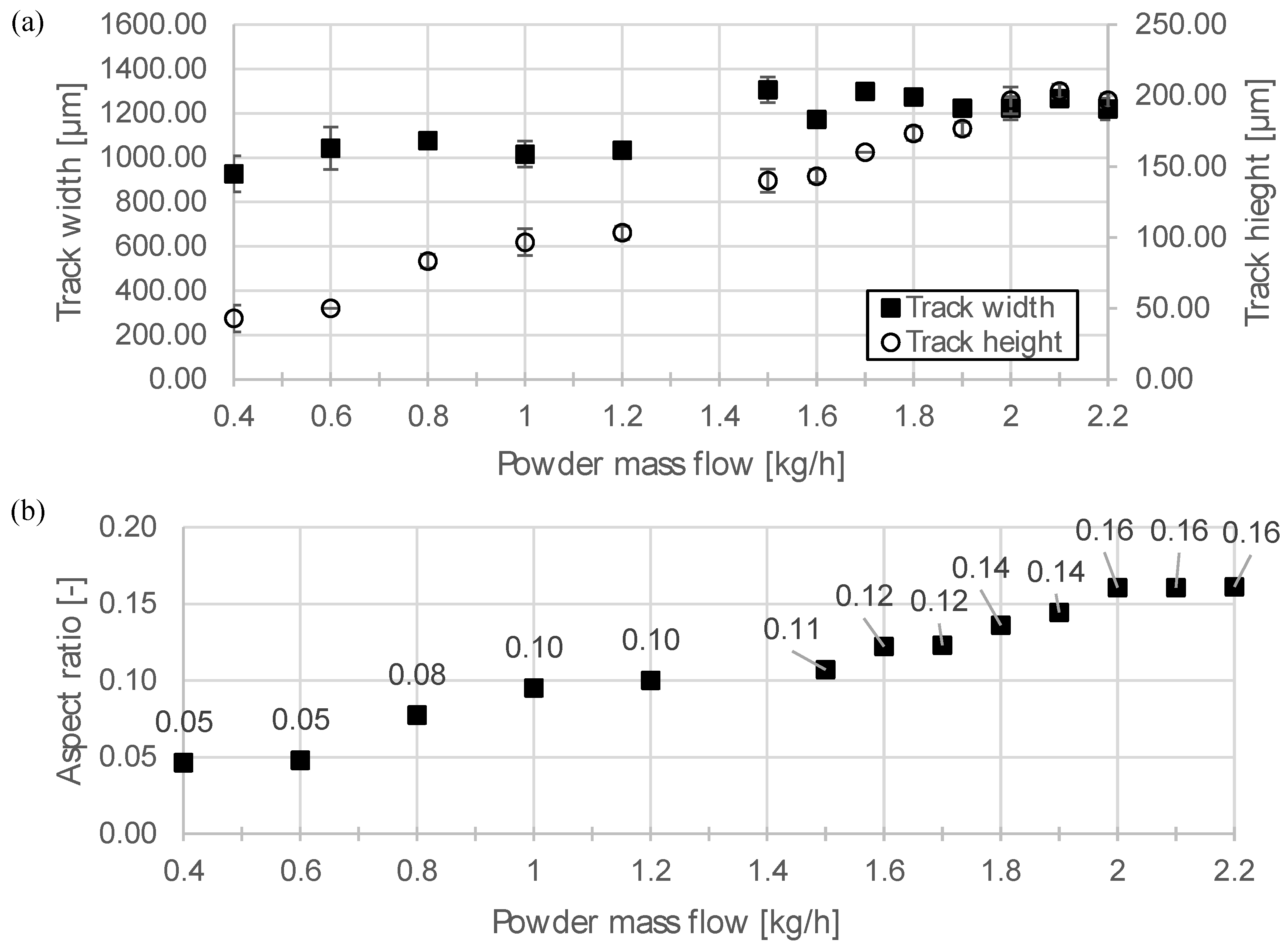
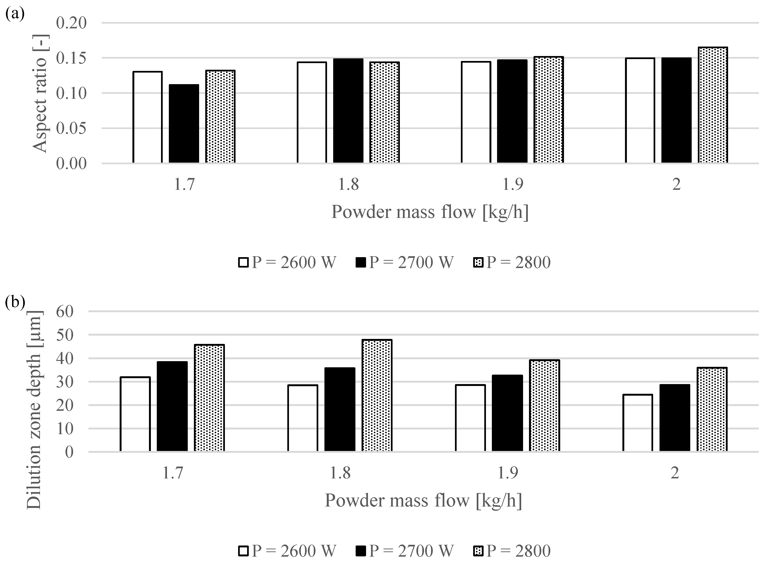
3.1. Single Track
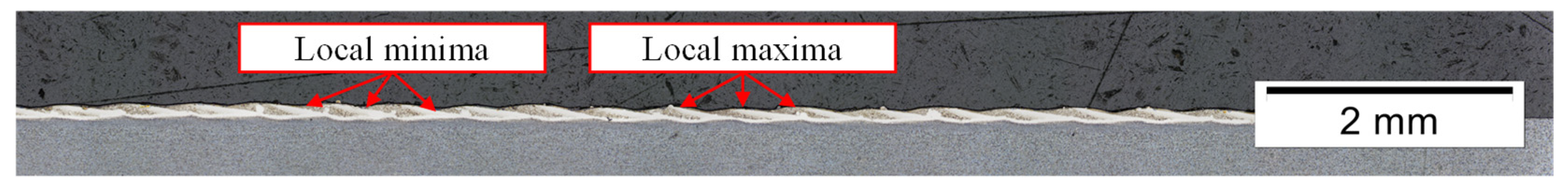
3.2. Coating
3.3. Volume
4. Conclusions
4.1. Single Track
- -
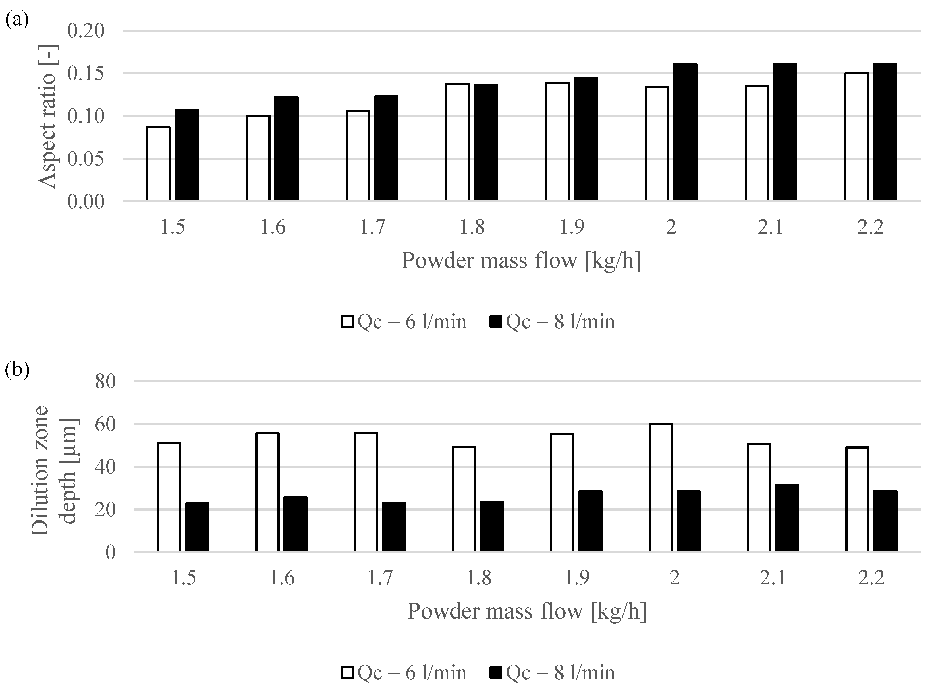
- Weld bead geometry: the resulting weld bead width is mainly influenced by the set beam diameter while the powder mass flow mainly affects the resulting single-track height. An increasing carrier gas flow also results in a small increase in the single-track height. The beam power only has a minor effect on the resulting single-track geometry;
- -
- Dilution zone: an increasing beam power results in an increasing dilution zone depth. Also, a major parameter which affects the dilution zone is the carrier gas flow because this parameter affects the interaction time between powder particle and laser beam in the EHLA process. Hence, the bonding to the substrate material as well as the generated heat input into the substrate can be controlled with the beam power and carrier gas flow.
4.2. Coating
- -
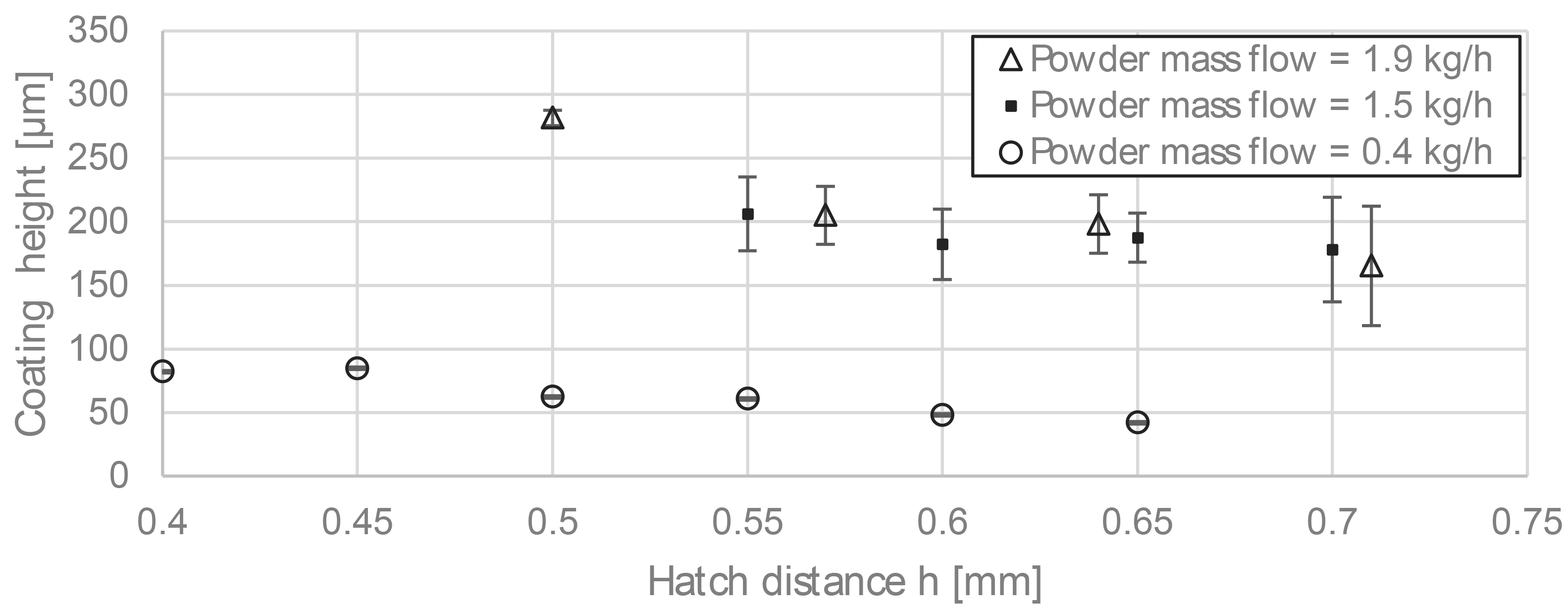
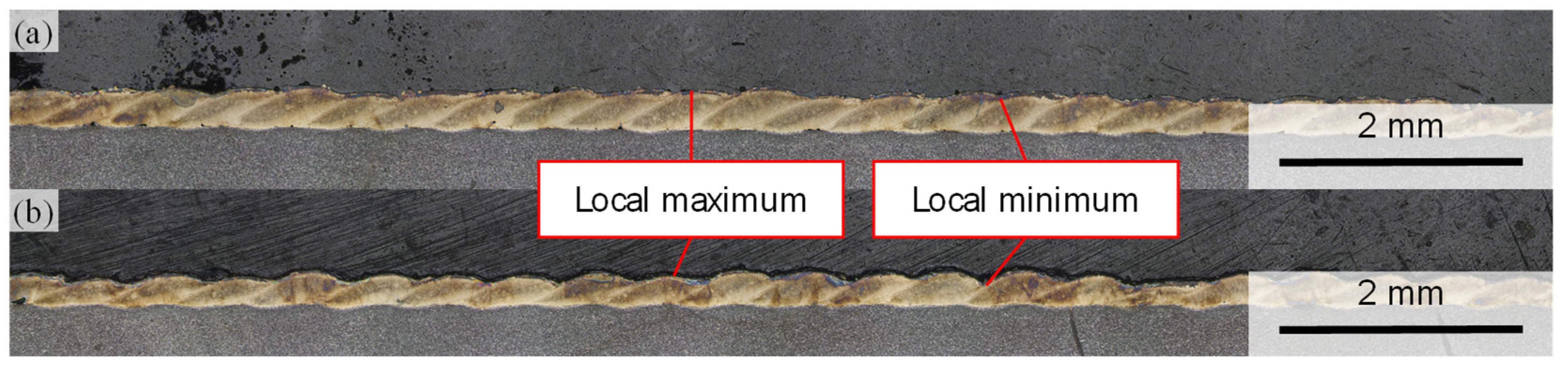
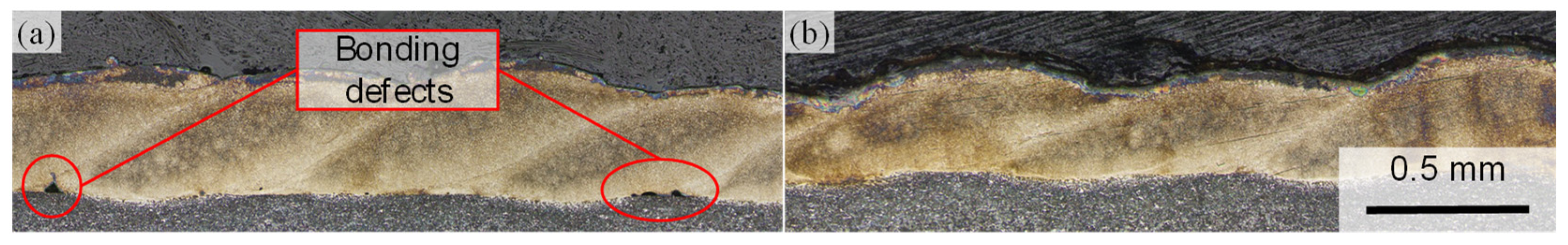
- The resulting coating thickness increases with a decreasing hatching parameter as a higher proportion of the prior deposited weld bead overlaps with the next deposited weld bead. The deviation of the coating thickness can be reduced with a decreasing hatching parameter; however, lack of bonding begins to occur at small hatching parameter within this study;
- -
- Coating parameters with a set powder mass flow of ṁ = 1.9 kg/h and ṁ = 0.4 kg/h were developed and result in an average coating thickness of 205 µm and 60 µm, respectively. Compared to the parameters provided in the literature, the powder mass flow is increased by 0.1 kg/h when applying the parameter set with a lower heat input. In the case of the parameter set with ṁ = 1.9 kg/h, the powder mass flow is increased by 1.6 kg/h;
- -
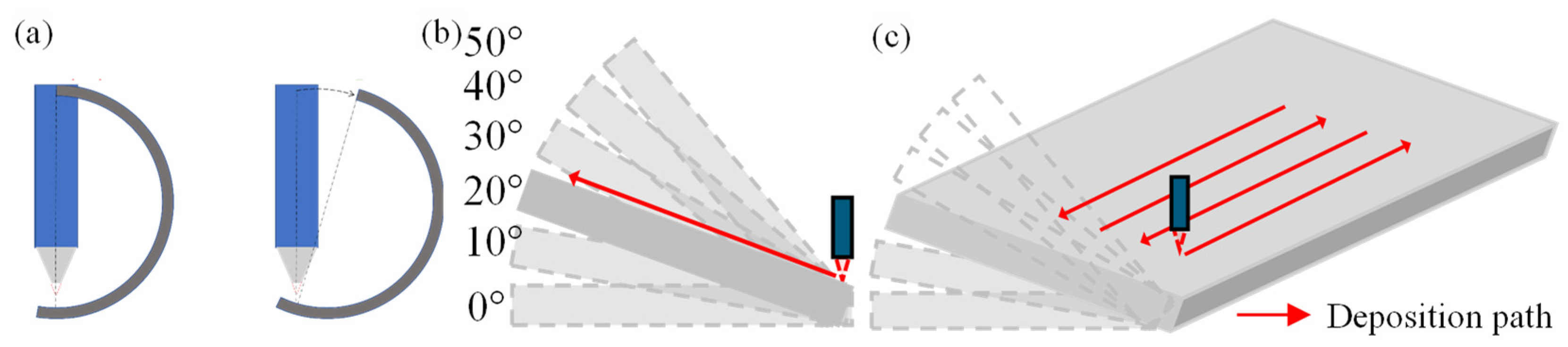
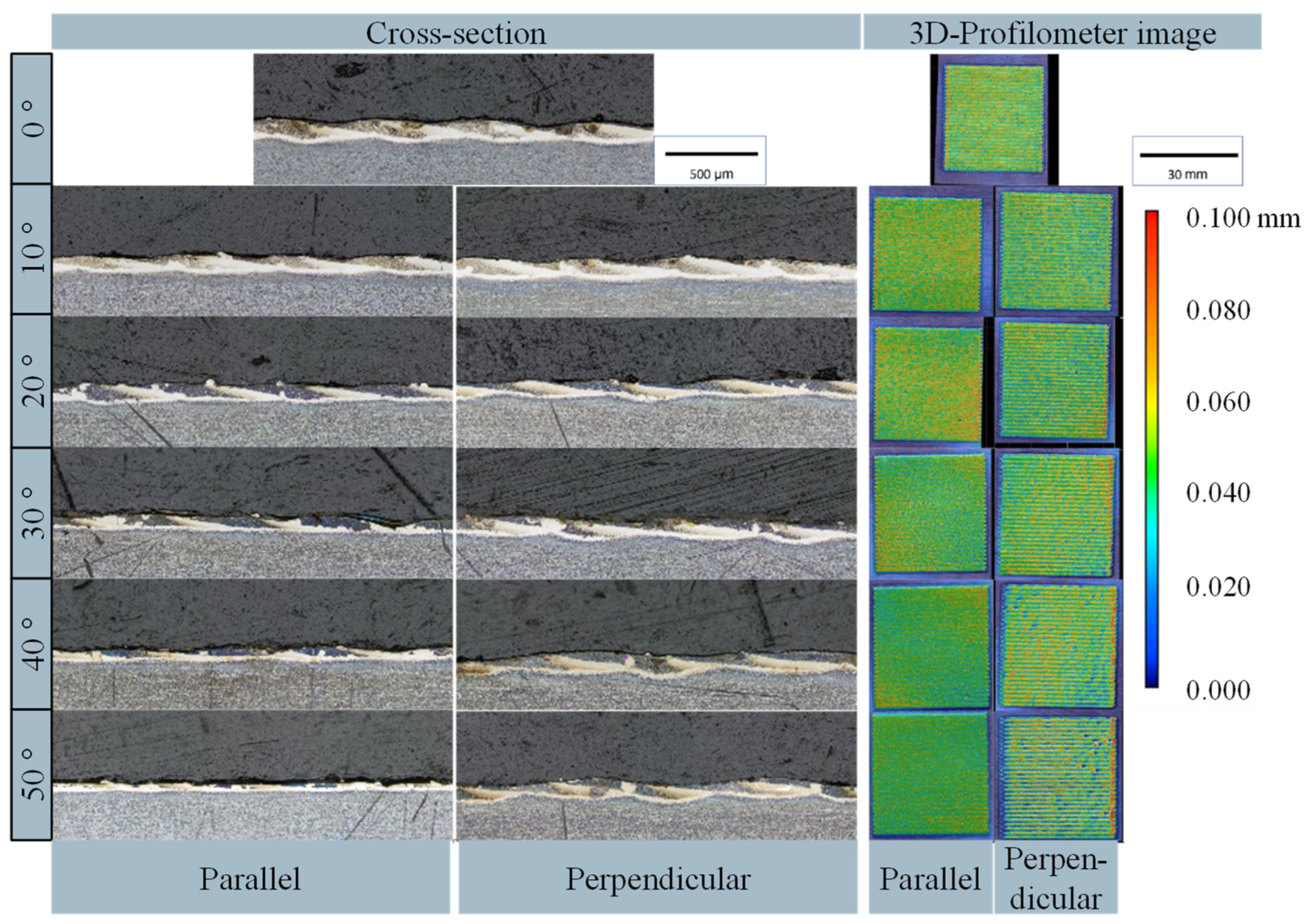
- The experiments with non-perpendicular deposition qualitatively indicate that the coating process tolerates a tilting angle of up to 20°. This can be potentially applied when a perpendicular deposition condition is not applicable due to interfering contours of a component.
4.3. Volume
- -
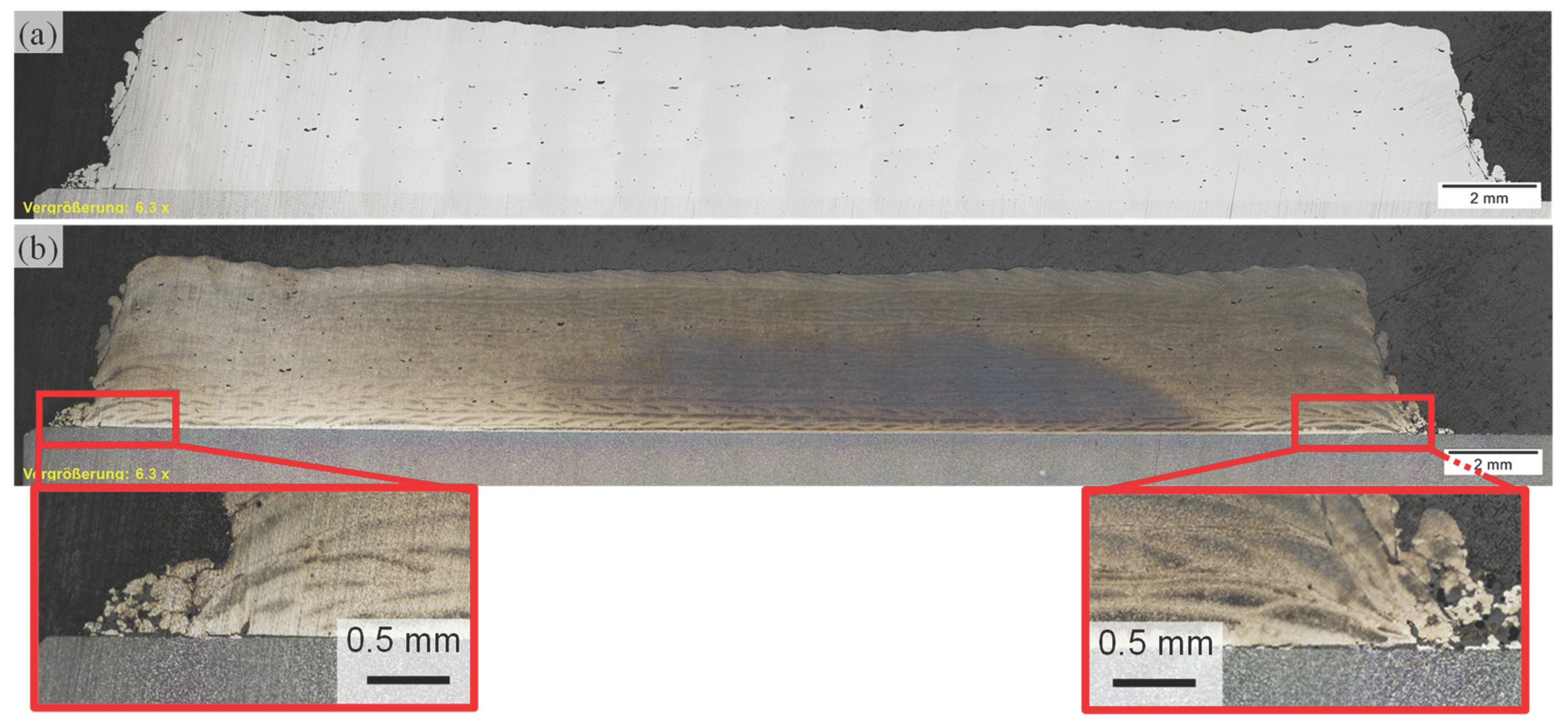
- Due to high thermal-induced stresses, which lead to crack formation in the bonding zone, the parameter set with ṁ = 1.9 kg/h cannot be applied for the deposition of bulk specimens. A variation in deposited geometries, which potentially prevents a crack formation, can be further investigated in following experiments;
- -
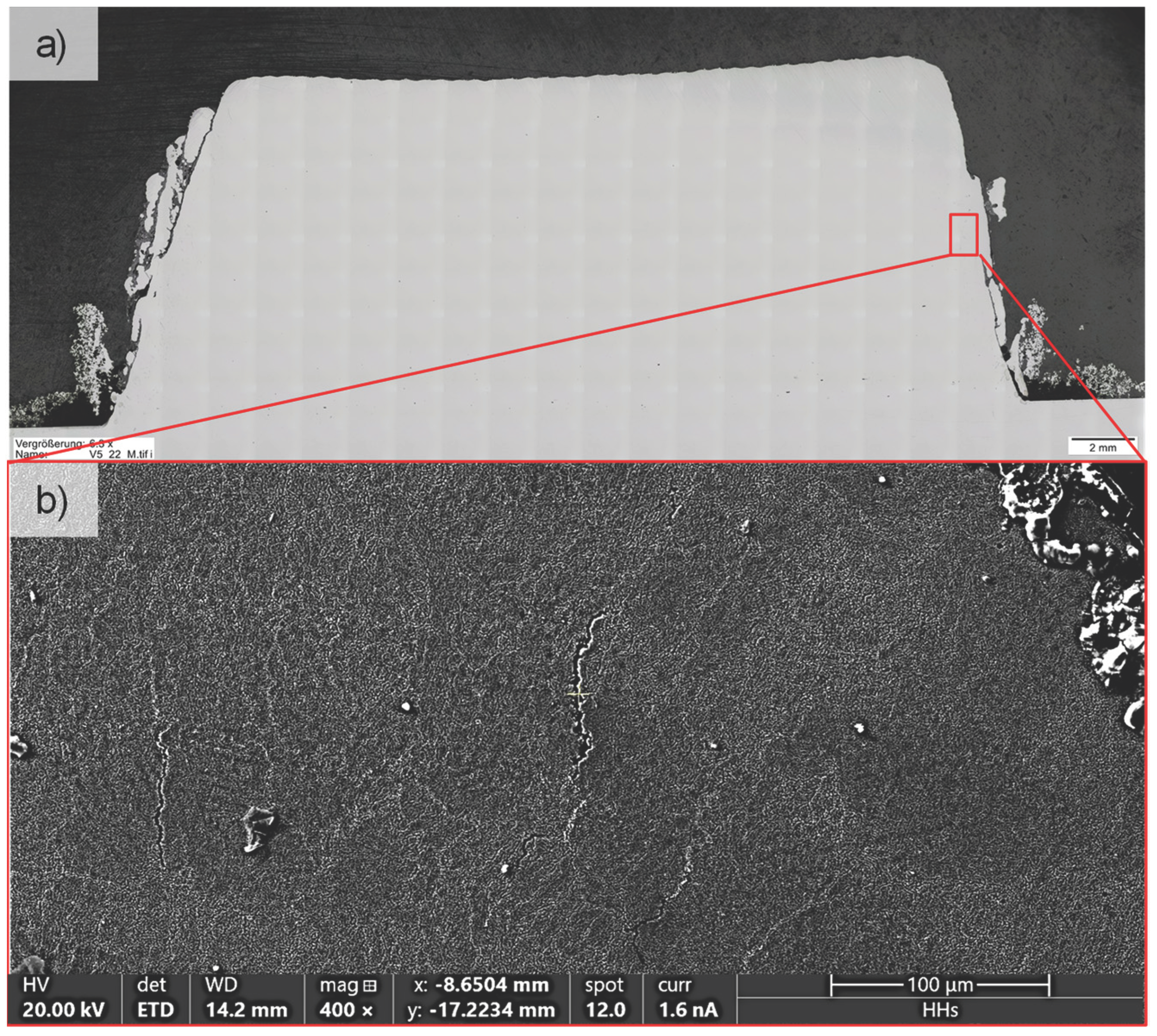
- Due to a lower generated heat input, a parameter set for additive manufacturing could be developed with the set powder mass flow of ṁ = 0.4 kg/h. However, the formation of micro cracks is identified at the area within 1 mm from the specimen edge, when bigger volumes are deposited. The micro defects need to be potentially removed in post-processing steps;
- -
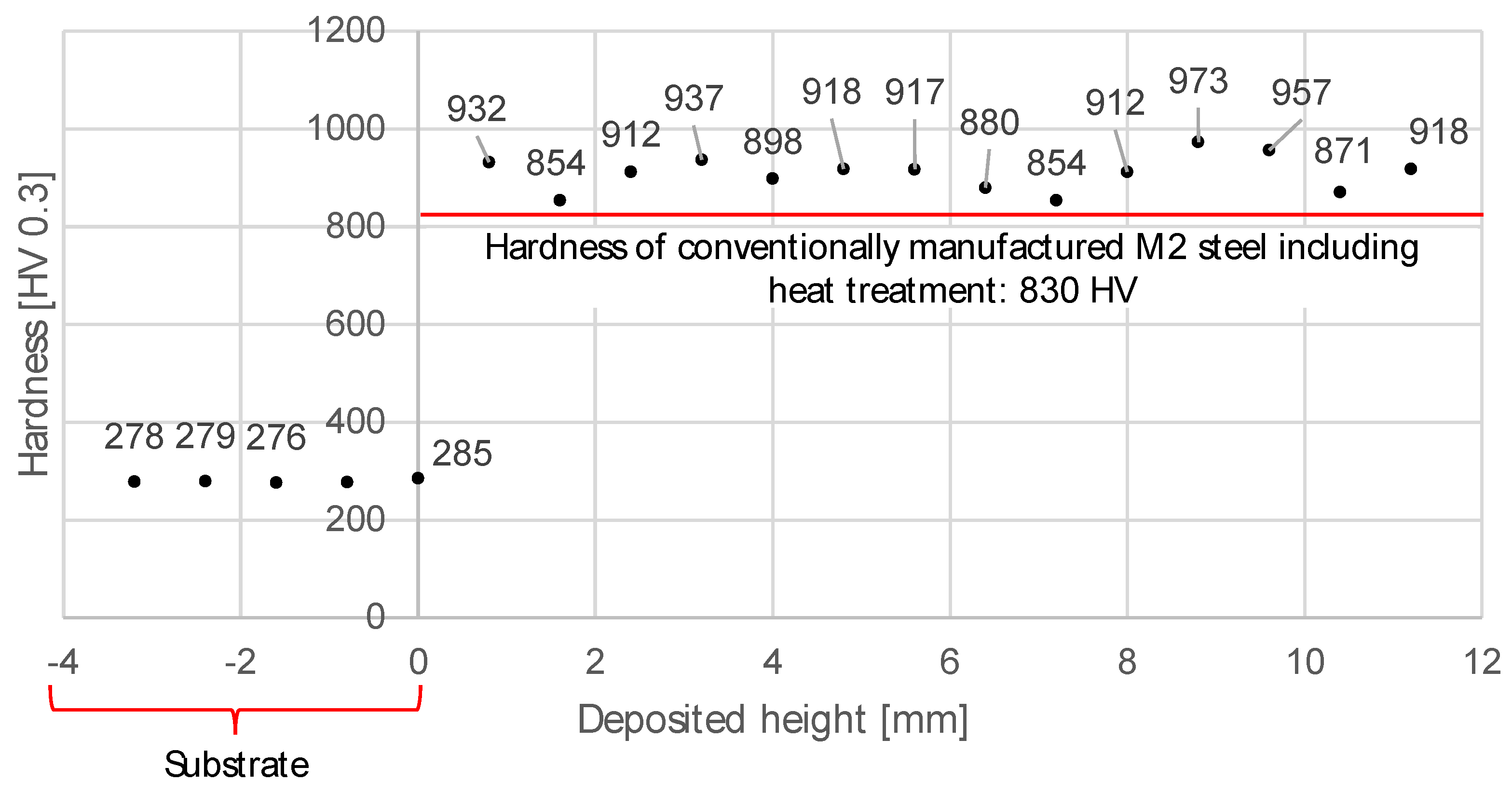
- The conducted hardness measurements on the bulk specimen validate that a hardness of ~900 HV can be achieved without heat treatment. As a conclusion, when post-processing steps are considered, the developed process parameter can be applied for the additive manufacturing of simple geometries or repair applications. To further investigate the feasibility of depositing more complex structures and geometries, future studies need to be extended with the deposition of different geometrical features.
Author Contributions
Funding
Institutional Review Board Statement
Informed Consent Statement
Data Availability Statement
Conflicts of Interest
References
- Kelbassa, I. Qualifizieren des Laserstrahl-Auftragschweißens von BLISKs aus Nickel- und Titanbasislegierungen. Ph.D. Thesis, Faculty of Mechanical Engineering, Aachen, Germany, 2006. [Google Scholar]
- Witzel, J. Qualifizierung des Laserstrahl-Auftragschweißens zur generativen Fertigung von Luftfahrtkomponenten. Ph.D. Thesis, Faculty of Mechanical Engineering, Aachen, Germany, 2015. [Google Scholar]
- Baek, G.Y.; Shin, G.Y.; Lee, E.M.; Shim, D.S.; Lee, K.Y.; Yoon, H.S.; Kim, M.H. Mechanical Characteristics of a Tool Steel Layer Deposited by Using Direct Energy Deposition. Met. Mater. Int. 2017, 23, 770–777. [Google Scholar] [CrossRef]
- Park, Y.K.; Ha, K.; Shin, K.Y.; Lee, K.Y.; Kim, D.J.; Kwon, S.H.; Lee, W. Wear resistance of direct-energy–deposited AISI M2 tool steel with and without post-heat treatment. Int. J. Adv. Manuf. Technol. 2021, 16, 3917–3931. [Google Scholar] [CrossRef]
- Svetlizky, D.; Zheng, B.; Vyatskikh, A.; Das, M.; Bose, S.; Bandyopadhyay, A.; Schoenung, J.M.; Lavernia, E.J.; Eliaz, N. Laser-based directed energy deposition (DED-LB) of advanced materials. Mater. Sci. Eng. A 2022, 840, 142967. [Google Scholar] [CrossRef]
- Bajaj, P.; Hariharan, A.; Kini, A.; Kürnsteiner, P.; Raabe, D.; Jägle, E.A. Steels in additive manufacturing: A review of their microstructure and properties. Mater. Sci. Eng. A 2020, 772, 138633. [Google Scholar] [CrossRef]
- Li, Y.; Wang, Y.; Niu, J.; Liu, S.; Lin, Y.; Liu, N.; Ma, J.; Zhang, Z.; Wang, J. Microstructure and mechanical properties of M2 high speed steel produced by electron beam melting. Mater. Sci. Eng. A 2023, 862, 144327. [Google Scholar] [CrossRef]
- Chaus, A.S.; Bračík, M.; Sahul, M.; Dománková, M. Microstructure and properties of M2 high-speed steel cast by the gravity and vacuum investment casting. Vacuum 2019, 162, 183–198. [Google Scholar] [CrossRef]
- Otai Special Steel M2 Tool Steel|1.3343|HS-6-5-2C|SKH51. Available online: https://www.astmsteel.com/product/m2-tool-steel-1-3343-hs-6-5-2c-skh51/ (accessed on 13 May 2024).
- Moritz, S.; Schwanekamp, T.; Reuber, M.; Lentz, J.; Boes, J.; Weber, S. Impact of in Situ Heat Treatment Effects during Laser-Based Powder Bed Fusion of 1.3343 High-Speed Steel with Preheating Temperatures up to 700 °C. Steel Res. Int. 2023, 94, 2200775. [Google Scholar] [CrossRef]
- Schopphoven, T. Experimentelle und modelltheoretische Untersuchungen zum Extremen Hochgeschwindigkeits-Laserauftragschweißen. Ph.D. Thesis, Faculty of Mechanical Engineering, Aachen, Germany, 2019. [Google Scholar]
- Xu, X.; Lu, H.; Qiu, J.; Luo, K.; Su, Y.; Xing, F.; Lu, J. High-speed-rate direct energy deposition of Fe-based stainless steel: Process optimization, microstructural features, corrosion and wear resistance. J. Manuf. Process. 2022, 75, 243–258. [Google Scholar] [CrossRef]
- Yong, Z.; Chang, L.; Jiang, S.; Xie, D.; Xing, F.; Shen, H.; Shen, L.; Tian, Z. Parameter optimization of T800 coating fabricated by EHLA based on response surface methodology. Opt. Laser Technol. 2023, 158, 108837. [Google Scholar] [CrossRef]
- Meghwal, A.; Pinches, S.; Anupam, A.; Lie, L.; Munroe, P.; Berndt, C.C.; Ang, A.S.M. Structure-property correlation of a CoCrFeNi medium-entropy alloy manufactured using extreme high-speed laser material deposition (EHLA). Intermetallics 2023, 152, 107769. [Google Scholar] [CrossRef]
- TRUMPF SE + Co. KG. Laser Metal Deposition—A Process for Various Applications. Available online: https://www.trumpf.com/en_INT/solutions/applications/additive-manufacturing/laser-metal-deposition/ (accessed on 4 June 2024).
- ponticon GmbH. Coating, Repair and Additive Manufacturing in Three Dimensions. Available online: https://ponticon.de/en/produkte/ (accessed on 4 June 2024).
- Bold, M.-N.; Schleifenbaum, J.H.; Schmitt, N. Application of the 3D-EHLA Process for Agile Alloy Development; Universitätsbibliothek der RWTH Aachen: Aachen, Germany, 2022. [Google Scholar]
- Makino Asia Pte Ltd. AML500 5-Axis CNC Machine for High-Speed DED. Available online: https://www.makino.com.sg/en-us/machine-technology/machines/laser-metal-deposition/aml500 (accessed on 3 January 2024).
- Schaible, J.; Sayk, L.; Schopphoven, T.; Schleifenbaum, J.H.; Häfner, C. Development of a high-speed laser material deposition process for additive manufacturing. J. Laser Appl. 2021, 33, 012021. [Google Scholar] [CrossRef]
- Ko, M.-U.; Zhang, Z.; Schopphoven, T. Process development and process adaption guidelines for the deposition of thin-walled structures with IN718 using extreme high-speed directed energy deposition (EHLA3D). J. Laser Appl. 2023, 35, 042059. [Google Scholar] [CrossRef]


| [wt.%] | |||||
|---|---|---|---|---|---|
| C | Si max. | Cr | Mo | V | W |
| 0.86–0.94 | 0.45 | 3.8–4.5 | 4.7–5.2 | 1.7–2.1 | 5.9–6.7 |
| Beam Diameter [mm] | Beam Power [W] | Powder Mass Flow [kg/h] | Carrier Gas Flow [l/min] | Feed Rate [m/min] |
|---|---|---|---|---|
| 1.4 | 2800 | 2.2 | 8 | 30 |
| 1.5 | ||||
| 1.6 | 1800–3000 | 0.4–2.2 | 6; 8 | |
| 1.7 | 2800 | 2.2 | 8 | |
| 1.8 |
| Parameter set: high productivity | PL [W] | ṁ [kg/h] | QC [L/min] | dB [mm] | Vf [m/min] |
| 2800 | 1.9 | 8 | 1.6 | 30 | |
| Single-track cross-section | 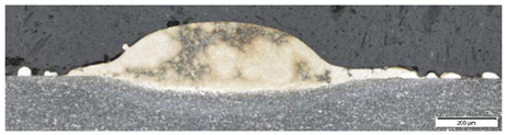 | ||||
| Single-track properties | Width [µm] | Height [µm] | Aspect ratio [-] | Dilution zone depth [µm] | |
| 1223 ± 26 | 176 ± 5 | 0.14 | 28.6 | ||
| Parameter set: Low heat input | PL [W] | ṁ [kg/h] | QC [L/min] | dB [mm] | Vf [m/min] |
| 2000 | 0.4 | 8 | 1.6 | 30 | |
| Single-track cross-section | 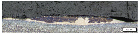 | ||||
| Single-track properties | Width [µm] | Height [µm] | Aspect ratio [-] | Dilution zone depth [µm] | |
| 927 ± 80 | 43 ± 9 | 0.05 | 39.0 | ||
| Parameter Set | PL [W] | ṁ [kg/h] | QC [L/min] | dB [mm] | Vf [m/min] | h [mm] | Coating Thickness [µm] |
|---|---|---|---|---|---|---|---|
| High productivity | 2800 | 1.9 | 8 | 1.6 | 30 | 0.6 | 205 ± 22 |
| Low heat input | 2000 | 0.4 | 0.55 | 60 ± 10 |
| Parameter Set | PL [W] | ṁ [kg/h] | QC [L/min] | dB [mm] | Vf [m/min] | h [mm] | ∆z [µm] |
|---|---|---|---|---|---|---|---|
| High productivity | 2800 | 1.9 | 8 | 1.6 | 30 | 0.6 | 190 |
| Low heat input | 2000 | 0.4 | 0.55 | 55 |
| PL [W] | Metallographic Cross-Section | Porosity [%] |
|---|---|---|
| 2100 | 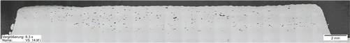 | 0.95 |
| 2000 | 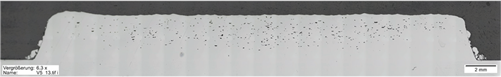 | 1.23 |
| 1800 | 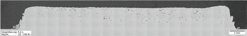 | 0.68 |
| 1600 | 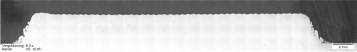 | 0.11 |
Disclaimer/Publisher’s Note: The statements, opinions and data contained in all publications are solely those of the individual author(s) and contributor(s) and not of MDPI and/or the editor(s). MDPI and/or the editor(s) disclaim responsibility for any injury to people or property resulting from any ideas, methods, instructions or products referred to in the content. |
© 2024 by the authors. Licensee MDPI, Basel, Switzerland. This article is an open access article distributed under the terms and conditions of the Creative Commons Attribution (CC BY) license (https://creativecommons.org/licenses/by/4.0/).
Share and Cite
Ko, M.-U.; Cüppers, J.; Schopphoven, T.; Häfner, C. Extreme High-Speed DED of AISI M2 Steel for Coating Application and Additive Manufacturing. Coatings 2024, 14, 953. https://doi.org/10.3390/coatings14080953
Ko M-U, Cüppers J, Schopphoven T, Häfner C. Extreme High-Speed DED of AISI M2 Steel for Coating Application and Additive Manufacturing. Coatings. 2024; 14(8):953. https://doi.org/10.3390/coatings14080953
Chicago/Turabian StyleKo, Min-Uh, Julius Cüppers, Thomas Schopphoven, and Constantin Häfner. 2024. "Extreme High-Speed DED of AISI M2 Steel for Coating Application and Additive Manufacturing" Coatings 14, no. 8: 953. https://doi.org/10.3390/coatings14080953
APA StyleKo, M.-U., Cüppers, J., Schopphoven, T., & Häfner, C. (2024). Extreme High-Speed DED of AISI M2 Steel for Coating Application and Additive Manufacturing. Coatings, 14(8), 953. https://doi.org/10.3390/coatings14080953