Abstract
Aiming its analysis at the poor hardness and wear-resistance of E690 high-strength steel, and the high hardness and good wear-resistance of AlCrN-coated, combined with the laser impact micro-modeling which can store oil lubrication, this paper carries out research on the synergistic wear reduction mechanism of laser impact micro-modeling AlCrN coated on the surface of E690 high-strength steel. Multi-arc ion plating technology is used to prepare the AlCrN coating on the laser-impact micro-modeling specimen; the micro-modeling AlCrN-coated specimen is subjected to a reciprocating friction test, and the hardness and residual stress of the coated surface are measured by equipment such as a residual stress meter and a microhardness tester. The microstructure and physical elements of the surface wear before and after the preparation of the coating are analyzed by scanning electron microscope (SEM), confocal three-dimensional morphometer and XRD diffractometer, respectively. The results show that the prepared AlCrN-coated materials were well-bonded to the substrate. Compared with the micro-molding-only specimens, the average friction coefficient and wear amount of the micro-molded AlCrN-coated specimens with different micro-molding densities and depths decreased compared with the micro-molded specimens; among them, the average friction coefficient of the specimens with a micro-molding density of 19.6% and a depth of 7.82 µm was 0.0936, which was the lowest. Additionally, the AlCrN coating enhances the stability of the friction process of the specimen and reduces the amount of wear of the specimen. Under the premise of ensuring the anti-wear and stability properties of the material, the best integrated friction performance was achieved at a micro-molding density of 19.6% and a depth of 24.72 µm. A synergistic wear reduction and lubrication model of micro-molding and AlCrN-coating was established.
1. Introduction
The pile leg rack and pinion lifting mechanism made of E690 high-strength steel is prone to failures (such as pitting corrosion, adhesion, wear, and plastic micro-deformation) of the tooth surface under extreme working conditions, which substantially threatens the safety of offshore platforms [1,2]. Laser impact micro-modeling technology (which does not compromise the surface integrity of the processed material) is applicable under high-pressure, heavy-load conditions and improves the tribological properties of the friction sub-surface. This is a new technology for extending the service life of the friction sub-surface [3,4,5]. It has found wide application in various fields, such as plain bearings [6], piston cylinder liners [7,8], and tool cutting. Multi-arc ion plating, a new coating preparation process, is widely used on the surface of mechanical parts to enhance their wear resistance and corrosion resistance [9]. AlCrN coatings exhibit high-temperature oxidation resistance and abrasive wear resistance, rendering them important for applications in tool cutting, mold forming, and critical gear protection [10,11]. Previous studies have combined laser surface micro-texturing with coating technology, but they have mainly focused on the effects of laser micro-texturing manufacturing and coating loaded on surfaces to assess friction properties under low-pressure as well as light-load conditions [12,13]. As an extension of laser micro-structuring and strengthening technology, research on the tribological properties of laser impact micro-structuring and coating composite treatment has recently emerged to address molding guidelines for materials used in offshore equipment, in addition to the wear-resistant properties of materials under high-pressure and heavy loads, as well as cyclic loading conditions.
In this paper, on the basis of the group’s previous experiments [14], AlCrN coating has the given advantages of high hardness, good wear resistance, and high interfacial bonding strength, which can make up for the defects of E690 high strength steel with low hardness and bad abrasion resistance, and, combined with the laser impact micro-modeling, can realize oil storage lubrication. This paper carries out the research on the mechanism of laser impact micro-modeling and AlCrN-coated synergistic abrasion reduction. Firstly, laser impact micro-modeling is carried out on the surface of E690 high-strength steel specimen; after that, AlCrN-coated with layered structure is prepared on the surface of the micro-modeling specimen; finally, a multifunctional friction and wear tester is used to carry out reciprocating friction test on micro-modeled, AlCrN-coated specimen to study the mechanism of laser impact micro-modeling and AlCrN-coated synergistic abrasion reduction. The research work in this paper provides a theoretical basis for improving the tribological performance of E690 high strength steel under a heavy load environment and extending its service life, which has important theoretical significance and engineering value.
2. Materials and Methods
2.1. Laser Impact Micro-Modeling
The specimen material of E690 high-strength steel, specifically, its material chemical composition and mechanical properties, are shown in Table 1. A sample of 30 mm × 25 mm × 5 mm specimen was shaped through wire-cutting material processing, according to ASTM E3 standards. In turn, 240–1200# sandpaper was used on the surface of the specimen for sanding and polishing; the use of diamond polishing agent ensures that the specimen is polished to a mirror surface, in addition to ultrasonic cleaning and blow-drying.

Table 1.
Chemical composites of E690 high-strength steel (mass fraction/%) and its mechanical capacity.
To investigate the effects of various micro-modeling densities on the friction properties, an yttrium aluminum garnet solid-state pulsed laser system (YS100-R200A, Tyrida, Xi’an, China) was used to perform laser impact micro-modeling on the surface of E690 high-strength steel; the laser shock wavelength was 1064 nm and the pulse width was 20 ns. The laser impact parameters were as follows: the spot diameter was 2 mm and the impact energy was 7 J. A single impact was applied; the micro-pit densities were set as 0%, 12.6%, 19.6%, 34.9%, and 50.3%. Subsequently, the AlCrN coating was prepared by using multi-arc ion plating technology to obtain various distribution densities of micro-pits. To investigate the effect of various pit depths on the friction performance, the specimens were subjected to various numbers of impacts (1× to 4×) at each location based on the optimal micro-pit density determined from tribological performance tests of AlCrN coatings with varying micro-pit densities. This enabled the generation of micro-pit distributions with varying depths.
2.2. Coating Preparation
The experiments were carried out by using multi-arc ion coating equipment (NANOARC-SP1010, Wuxi Naarc New Material Technology, Wuxi, China). The E690 high-strength steel specimens were fixed on a turntable rotating at a frequency of 20 Hz. The substrate was pre-treated before deposition, and the surface of the specimens was cleaned by argon ion glow for 15 min. A 99.9% pure chromium (Cr) target and aluminum (Al) target were used. Nitrogen gas (N2) with a purity of 99.99% was introduced into the chamber as a reactive gas to obtain the AlCrN coating. Table 2 shows the detailed deposition parameters for this experiment. The deposition rate and coating thickness were determined by the arc current as well as the deposition time. Figure 1 shows the combined preparation process of laser impact micro-molding treatment and coating deposition on E690 high-strength steel substrates. Of these, LSP stands for laser shock peening technology.
Table 2.
Deposition parameters.
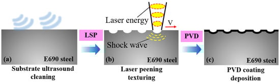
Figure 1.
Preparation of an AlCrN coating on a laser impact micro-modeling surface.
2.3. Friction Wear Test
A multifunctional friction and wear tester (MRT-5000, Rtec, San Jose, CA, USA) was used for conducting friction tests as well as wear tests. The main parameters were as follows: resolution of 1 µm; speed range of 0.001–10 mm/s; and loading force resolution of 5 mN for 1–100 N, and 250 mN for 100–5000 N. The linear reciprocating module was used to simulate the working conditions of the wear pins in this test. High-carbon chromium-bearing steel GCr15 (with a diameter of φ10 mm and a hardness of 900 HV) was selected as the material for the wear pins.
The test was conducted under oil-poor lubrication conditions, and the lubricant was 30# mechanical oil. According with ASTM G133 standard, a constant load of 100 N, a constant speed of 0.2 m/s, a frequency of 5 Hz, a time of 600 s, and a temperature of 25 °C were used.
2.4. Analysis and Testing
The surface, cross-section and surface morphology of the AlCrN-coated specimens after the friction and wear experiments were observed by scanning electron microscopy (Quanta 650F, FEI Corporation, Hillsboro, OR, USA) (SEM) with an operating voltage of 10 kV. A confocal microscope (usurf, NanoFocus, Oberhausen, Germany) was used to observe the surface three-dimensional morphology of the AlCrN-coated specimens after the friction wear experiments and to extract the geometric feature data. The crystal structure and phase structure of the AlCrN coating were detected with an X-ray (Ultima IV, Rigaku Corporation, Tokyo, Japan) diffractometer, with a scanning range from 5° to 90°. A microhardness tester (TMVS-1 type, Beijing Times Peak Technology, Beijing, China) was used for the hardness test according to the ASTM E92 standard, with an interval of 0.3 mm between each measurement point; a total of six points were measured, the loading force was 200 g, and the retention time was 15 s in order to obtain the average microhardness value of the sample surface. An X-ray stress analyzer (Xstress 3000 G2R, STRESSTECH OY, Jyväskylä, Finland) was used to detect the residual stresses on the surface of the E690 high-strength steel matrix and the AlCrN-coated material, and the tilting method was chosen as the test method; five measurement points were selected on the surface of the specimen for the test, and the measurement of each point was repeated three times to take the average value. The basic parameters of the residual stresses test were as follows: collimation tube diameter, 1 mm; target material, Cr; Bragg angle, 156.4°; tube voltage, 30 kV; tube current, 6.7 mA; exposure time, 14 s; and iron, ferrite (211) crystal type. A scratch tester (WS-2005, Lanzhou Zhongke Kaihua, Lanzhou, China) was used to detect the adhesion between the AlCrN coating and the substrate; the average of three measurements was reported as the engineering bond strength of the interfacial bond.
3. Results
3.1. Analysis of AlCrN Coating Properties
3.1.1. Surface Topography
Figure 2 shows the surface morphology of an AlCrN coating prepared on a micro-modeling specimen. The surface exhibited a uniform matte black color and good adhesion with the substrate, with a smooth coating surface, high film densities, and micro-pit arrays that were clearly visible.
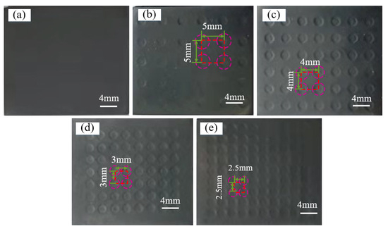
Figure 2.
Morphology of specimens with various micro-modeling densities after surface coating: (a) 0%; (b) 12.6%; (c) 19.6%; (d) 34.9%; (e) 50.3%.
Figure 3 shows the SEM morphology of the AlCrN-coated surface and regional surface sweeps. Figure 3c shows an enlarged view of the red-boxed area in Figure 3a. The AlCrN coating surface was smooth, with no obvious defects such as pinholes and bubble flaking, and no uncoated areas (Figure 3a–c). The elemental distribution on the coating surface was obtained by energy-dispersive X-ray spectroscopy (EDS) elemental energy spectrum face-sweeping of the AlCrN coating’s surface (Figure 3d–h). The coating on the specimen surface was continuous and complete, with a uniform distribution of elements, and there were no additional impurities or obvious defects. Figure 4 shows the EDS elemental detection analysis of Figure 3c. According to the EDS analysis results, the chemical elements of the coating mainly contain the elements of Al, Cr, N, C, O and Fe, and the atomic fractions of Al, Cr and N are 26.8%, 13.3%, and 48.29%, respectively. In addition to the elements of Al, Cr, and N, there are also the elements of C, Fe, and O in the AlCrN-coating, and the elements of C and Fe are the result of the measurement of the X-ray penetrating the coating to reach the substrate of the E690 high-tensile steel. The C and Fe elements are measured due to X-ray penetration of the coating into the E690 high-tensile steel substrate, while the oxygen element is the result of the oxidation reaction of the coating’s surface in contact with the air.
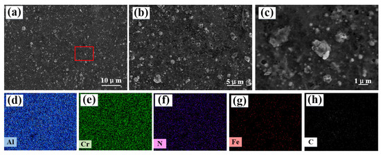
Figure 3.
Morphology of an AlCrN coating’s surface and a regional surface sweep analysis: (a–c) surface morphology as per scanning electron microscopy (SEM); (d–h) regional element distribution as per energy-dispersive X-ray spectroscopy (EDS).
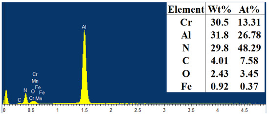
Figure 4.
EDS elemental analysis of localized regions on the surface of an AlCrN-coated specimen.
3.1.2. Phase Analysis
Figure 5 shows a typical X-ray diffraction pattern of the AlCrN coating. The diffraction peaks of the E690 high-strength steel matrix were relatively sharp; in particular, the (110) diffraction peak exhibited the largest peak-to-height ratio in the spectrum, indicating a highly crystalline matrix with a (110) crystal plane. Thus, the material was an iron-based solid solution with a body-centered cubic structure [15]. The diffraction peak (111) exhibited the highest intensity in the AlCrN coating, whereas the diffraction peak (220) had a lower intensity. During vapor deposition, the effects of the bias pressure and magnetic field lead to high energy as well as strong bombardment of aluminum and chromium ions. Additionally, the higher atomic density of the (111) facet in the face-centered cubic structure renders this crystal plane more susceptible to ion sputtering effects. As a result, grains tend to grow with a preferred orientation, whereas grains with other orientations are selectively sputtered. The main physical phase of the AlCrN coating is the solid solution fcc-(Cr,Al) N phase [16]. The aforementioned crystalline and amorphous phases were hard phases that improved the coating’s wear resistance and can extend the material’s service life.
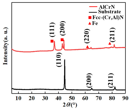
Figure 5.
X-ray diffraction analysis of the AlCrN-coated surface. FCC: face-centered cubic.
3.1.3. Microhardness and Residual Stress
Figure 6 shows the surface hardness and residual stress of a micro-pit in the radial direction. The surface hardness after laser impact was improved compared with the base sample; the overall hardness trend was a gradual decrease along the radial direction from the spot center. The average hardness value of the E690 high-strength steel base sample was 373.3 HV. With an increasing number of impacts (one to four), the hardness value at the center of the spot was increased by 8.0%, 11.28%, 15.64%, and 16.53% compared with the base sample, respectively, with the rate of increase gradually decreasing. Thus, after one to three impacts, the surface grains of the material were gradually refined, with a substantial increase in the number of grain boundaries and improved resistance to external deformation [14]. After four impacts, the surface grains were refined to the nanometer scale, forming a nanocrystalline structure, and the surface organization became more uniform, resulting in saturation of hardness at the macroscopic level. The average hardness composite of the E690 high-strength steel substrate after applying the AlCrN coating was 508.9 HV, which is 36.32% higher than that of the base sample, improving the wear resistance.
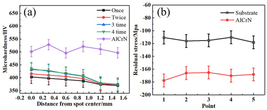
Figure 6.
Surface hardness and residual stress of the AlCrN coatings: (a) surface hardness; (b) surface residual stresses.
Figure 6b shows the residual stress on the surface of the AlCrN coating. The average residual stress of the E690 high-strength steel matrix was −114.1 MPa, whereas the average residual stress on the surface of the AlCrN coating was −169.5 MPa. The residual stresses of the matrix and coating were uniformly distributed, with no obvious areas of stress concentration; furthermore, the difference between the stress values of the matrix and the coating was relatively small. These facts correspond to improved bonding strength between the coating and substrate, which can facilitate stress transfer and reduce the risk of coating failure.
3.1.4. Bonding Strength of the Coating to the Substrate
Figure 7 shows the engineering bond-strength test of the AlCrN coating bonded to the substrate. As the dynamic normal load increased, the depth and width of the scratches on the surface of the coating increased, and tiny fragments were evident at the end of the scratches. A small portion of the coating peeled away from the substrate. At this point, the instrument emitted a strong sharp acoustic signal and the slope of the corresponding friction curve abruptly changed; this indicated the critical load, which represents the engineering bond strength of the coating [17]. The engineering bond strength of the coating to the substrate was approximately 35 N.
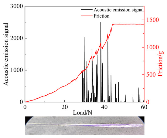
Figure 7.
AlCrN coating engineering bond-strength test.
Figure 8a,b show cross-sectional SEM images of the bonding region of the AlCrN coating with the E690 high-strength steel matrix and a corresponding EDS line sweep. Al, Cr, and N in the coating formed a step transition distribution at the bonding interface, indicating that these three atoms diffused in a manner that facilitated formation of a metallurgical bond at the bonding interface. The dense structure did not exhibit coarse columnar grains or pores, and the coating had a good bonding force with the substrate.
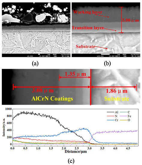
Figure 8.
SEM and EDS line-scan analysis of a cross-section of the AlCrN coating bonded to the substrate: (a) SEM image of cross-section; (b) SEM enlargement of cross-section; (c) EDS line scan of coating cross-section.
Figure 8c shows an EDS line scan of a cross-section of the AlCrN coating and substrate. The coating was mainly divided into the substrate, composite layer, and working layer. Among them, in the composite layer, combined with the EDS line-scan analysis of the AlCrN-coated cross-section, it was learned that the different contents of Al, Cr, and Fe lead to the emergence of different delaminations of the 1.35 µm regional layer, which are the Al-rich coating, with the widest thickness, closest to the side of the outermost Al layer; the Cr-rich transition layer, with the smallest thickness, in the middle; and the bonded Cr- and Fe-containing layer close to the side of the Fe matrix, respectively. The coating element combined with the substrate consisted mainly of Cr; the thickness of this over-coating was ca. 0.25 µm, enhancing the bonding performance of the coating because of the similarity in atomic radii between chromium and iron. The second and third layers of the coating were composite layers of Cr, Al, N, and other elements; the infiltration of aluminum and nitrogen elements can correspond to the formation of compounds with chromium elements in a manner that enhances their stability. The most superficial layer of the coating was dominated by the distribution of aluminum; its thickness was ca. 1.73 µm. The Al2O3 oxide layer can be generated by the aluminum element in friction wear [18]; since Al2O3 is a ceramic material with high hardness, the generation of Al2O3 on the surface of the coating increases the hardness and abrasion resistance of the coating, which makes the coating more resistant to surface abrasion and scratches; this enhances the friction and wear performance. In summary, the coating and substrate formed a diffusion interface, improving the interfacial bond strength.
3.2. Tribological Performance of Micro-Molded AlCrN-Coated Specimens
3.2.1. Analysis of Various Densities
The following friction test parameters were selected: normal load of 100 N, reciprocating frequency of 4 Hz, and test time of 600 s. Figure 9 shows the friction coefficients at various densities. During the initial stage of reciprocating friction, the friction coefficients of the micro-molded AlCrN-coated specimens exhibited a decreasing trend before reaching stability. This can be attributed to the large surface roughness of the specimens and the point contacts at the friction sub-contacts. Comparing the friction coefficient curves with the geometric area formed by the horizontal and vertical coordinates, the overall friction coefficient of the uncoated base sample was higher, and the friction process fluctuated greatly. Compared with the uncoated base samples, the micro-molded specimens with densities of 12.6%, 19.6%, and 34.9% exhibited lower and less-fluctuating friction coefficients. The friction coefficients fluctuated substantially only in the initial stage, when the micro-molding density was 34.9%, and then quickly stabilized. Because of the reduced distance between the micro-pits, when the micro-molding density was 50.3%, the effective contact area of the upper and lower specimens became smaller due to the reduction of the pit spacing; the raised edges of the pits led to part of the contact being changed to a point contact, which aggravated the friction and increased the fluctuation of the friction coefficient. At the same time, with the increase of micro-molding density, the processing cost increases, so the higher micro-molding density is not beneficial to the friction and wear performance.
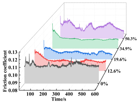
Figure 9.
Friction coefficients of micro-molded AlCrN-coated specimens with various densities.
Figure 10 shows the average friction coefficient and wear extent of various densities of micro-molded specimens and micro-molded AlCrN-coated specimens; among them, LPT stands for laser shock texturing. The friction coefficient and wear extent of the specimens after various process treatments were minimized. The coating reduced the average coefficient of friction of the micro-molded specimens with various distribution densities by 4.3%, 1.3%, 0.6%, 11.4%, and 7.7% (compared with the uncoated micro-molded specimens) (Figure 10a). The coated specimens with 34.9% micro-molding density exhibited the most substantial improvement in friction performance, and the coated specimens with 19.6% micro-molding density exhibited the best friction performance. The coating reduced the average wear of micro-molded specimens with various distribution densities by 37.8%, 36.9%, 34.9%, 43.5%, and 41.5% (compared with the uncoated micro-molded specimens) (Figure 10b), with the most substantial reduction in the average wear of coated specimens, with 34.9% micro-molding density. The coated specimens with 19.6% micro-molding density had the least extent of average wear.
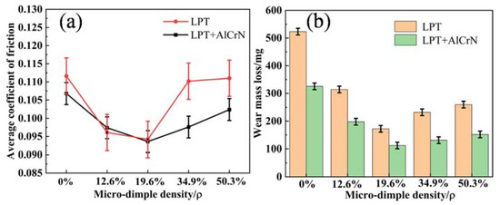
Figure 10.
Micro-molded coated specimens: (a) average coefficient of friction; (b) wear extent.
In summary, the change of micro-molding density was the main contributor to the friction coefficient, and the AlCrN coating had a good effect on wear reduction as well as lubrication, with the average friction coefficient decreasing by 5.1% and the average wear decreasing by 38.9%. The micro-molded AlCrN-coated specimens with 19.6% micro-molding density had the best friction performance and the smallest extent of wear among the tested samples.
3.2.2. Analysis of Various Depths
In accordance with the friction test results in Section 3.2.1, specimens with a micro-molding density of 19.6% and depths of micro-molding coatings of 7.82, 14.52, 24.72, and 31.39 µm were selected for friction tests. The parameters of the friction test were as follows: normal load of 100 N, reciprocating motion frequency of 4 Hz, and duration of 600 s. Figure 11 shows the friction coefficients of the specimens. The slope of the curve was larger during the friction period and the friction coefficient then increased rapidly. The specimen with a micro-pit depth of 24.72 µm quickly entered the stabilization stage after a brief friction period, exhibiting minimal fluctuation and good stability.
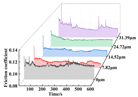
Figure 11.
Friction coefficients of micro-molded AlCrN-coated specimens of various depths.
Figure 12 shows the average coefficients of friction and wear. Observing Figure 12a, it can be seen that when the surface of the micro-molded specimen is not prepared with coating, the COF of the micro-molding specimen was at its lowest when the depth of the micro-molding pit was 7.82 micrometers, and with the increase of the depth of the micro-molding pit, the COF of the micro-molded specimen was sharply increased. After the coating was prepared on the surface of the micro-molded specimens, when the depth of micro-molding was in the range of 7.82–24.72 micrometers, the COF of the micro-molded AlCrN-coated specimens remained basically unchanged with the increase of the depth of micro-molding pits; the coating significantly improved the friction and wear resistance of the micro-molded specimens. The AlCrN coating reduced the average friction coefficients of the specimens with various depths by 4.3%, 0.64%, 5.75%, 8.55%, and 2.68% (compared with the uncoated micro-molded specimens), with the most obvious improvement in friction performance at a depth of 24.72 µm. The friction coefficients of the specimens were basically the same when the micro-pit depth was 7.82–24.72 µm (i.e., one to three laser impacts), and the friction coefficients of the specimens increased dramatically when the micro-pit depth was 31.39 µm (i.e., four laser impacts). Combined with the friction wear curves of the specimens at different depths in Figure 11, it can be seen that, in the above range of micro-molding depths, the fluctuation of the friction wear curves of the specimens decreases and the stability improves with the increase of the depth. That is, when the micro-molding depth is 24.72 µm, the micro-molded AlCrN-coated specimen rapidly enters into a stable stage after a short break-in period, and its fluctuation is the smallest and its stability is good. Observing Figure 12a, it can be seen that the coating reduced the average wear of the specimens with various depths by 37.8%, 34.9%, 32.2%, 36.1%, and 34.96% (compared with the uncoated micro-molded specimens), with the most pronounced reduction in the average wear for the coated specimens. The wear extents of the coated specimens with various micro-molding depths were much lower than those of the uncoated specimens, the least being a micro-molding depth of 24.72 µm.
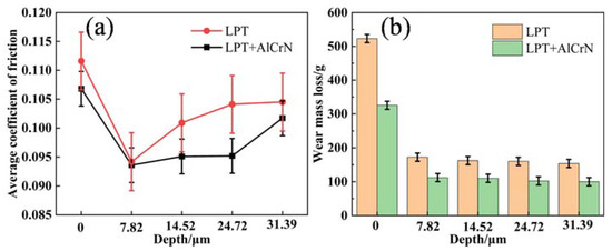
Figure 12.
Micro-molded AlCrN-coated specimens of various depths: (a) average friction coefficient; (b) wear extent.
To summarize, the AlCrN coating improved the edge bumping effect of micro-pits caused by laser impact, reduced friction, and improved lubrication, while the average coefficient of friction of micro-molded AlCrN-coated specimens with different depths was reduced by 4.38%, and the average amount of wear was reduced by 35.19%. According to the above analysis, when the micro-molding density is fixed at 19.6%, the friction process of the micro-molded AlCrN-coated specimens with a micro-molding depth of 24.72 µm is the most stable, and the coefficient of friction and the amount of abrasion are relatively low, which, combined with the results of the previous experiments [14], indicates that the increased depth can accommodate more abrasive particles and debris as well as enhance the oil storage capacity, which results in an increase in the friction life of the specimens. Therefore, to summarize, when the micro-molding density of AlCrN-coated specimens is 19.6%, the coated specimens with 24.72 µm micro-molding depth have the best friction performance and the least amount of wear; their coefficient of friction decreases by 8.55% and the amount of wear decreases by 36.1%.
3.3. Wear Surface Morphology Analysis of Micro-Molded AlCrN-Coated Specimens
3.3.1. Analysis of Various Densities
Figure 13 shows the SEM morphology of the wear surface, and Figure 14 shows the three-dimensional morphology of the wear surface. The surface of the non-molded specimens’ coating was substantially worn, exhibiting deep furrows and scattered fine abrasive grains, along with a substantial accumulation of attachments and micro-bumps along the wear track (Figure 13a and Figure 14a). Moreover, the normal load caused some abrasive particles to become embedded in the wear surface, resulting in micro-cutting and stress concentration on the coating surface during the friction test. This led to the formation of micro-cracks on the surface of the coating and extensive detachment along the wear direction, ultimately causing coating failure.
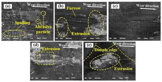
Figure 13.
Morphology, as per SEM, of the wear surface at various densities of micro-molded AlCrN-coated specimens: (a) 0%; (b) 12.6%; (c) 19.6%; (d) 34.9%; (e) 50.3%.
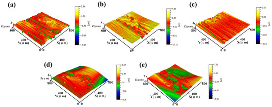
Figure 14.
Three-dimensional morphology of the wear surface of micro-molded AlCrN-coated specimens with various densities: (a) 0%; (b) 12.6%; (c) 19.6%; (d) 34.9%; (e) 50.3%.
Comparative observation of Figure 13b and Figure 14b shows that, compared with the specimen without modeling coating, the surface of the micro-modeled AlCrN-coated specimen with a distribution density of 12.6% has a lower oil storage capacity due to the lower density of the pits, such that the lubricant is consumed very quickly in the friction process, the micro-pits are quickly smoothed out, the degree of abrasion is more serious, the wear material shed in the friction pin is gathered to form abrasive wear, and the AlCrN coating partially spalls along the direction of wear because of the low hardness of the friction pin. Due to the low hardness of the friction pins, the abrasive wear is formed by the aggregation of abrasive particles, and the AlCrN coating is partially peeled off along the direction of wear.
The surface of the micro-molded AlCrN-coated specimen with a distribution density of 19.6% exhibited minimal wear damage, with only a few shallow scratches, compared with the corresponding specimen with a distribution density of 12.6% (Figure 13c and Figure 14c). Thus, the combination of micro-molding with a distribution density of 19.6% and an AlCrN coating improved the furrow effect. Additionally, the micro-molding craters stored abrasive particles during the friction process, which substantially reduced the wear of the coating surface. Compared with the corresponding specimen with a distribution density of 19.6%, the edge of the micro-pit of the micro-molded AlCrN-coated specimen with a distribution density of 34.9% experienced stress concentration, leading to formation of abrasive particles from surface plastic deformation (Figure 13d and Figure 14d). Some of these abrasive particles dispersed into the friction sub-surface along with the flow of lubricating oil, aggravating the wear. The edges of the micro-pits of the corresponding specimen with a distribution density of 50.3% were still clearly visible (Figure 13e and Figure 14e). The fluctuation of the surface contour and the edge effect of the raised micro-pits produced stress concentration in the surface coating, and there was flaking of the coating on the adjacent planes of the micro-pits. Upon complete wearing of the micro-pits, previously stored wear debris will be released and participate in the sliding wear of the steel substrate, resulting in deep wear marks.
In summary, the observation of the wear surface morphology indicates that the micro-molding–AlCrN-coating composite process had a substantial effect on reducing wear and improving the lubrication of E690 high-strength steel. The coated specimen with a micro-molding density of 19.6% exhibited the best friction performance among the tested samples, which is consistent with the findings in Section 3.2.1.
3.3.2. Analysis of Various Depths
At a micro-molding density of 19.6%, various depths of micro-molded AlCrN specimens were chosen to carry out friction wear tests. Figure 15 shows the morphology, as per SEM, of the wear surface, and Figure 16 shows the three-dimensional morphology. When the depth of micro-molding was 7.82–14.52 µm (i.e., 1× to 2× laser impacts), the coating was not completely destroyed during the abrasion test (Figure 15a,b and Figure 16a,b). Only a small number of scratches and abrasive particles were evident, and the coating did not exhibit adhesive wear phenomena. Thus, the coated specimen demonstrated good abrasion resistance. When the depth of the micro-molding was 24.72–31.39 µm (i.e., 3× to 4× laser impacts), the edges of the micro-molding were still clearly visible (Figure 15c,d and Figure 16c,d). Additionally, the coating in the inner part of the micro-molding remained undamaged, and some of the abrasive particles had been collected, resulting in the good abrasion resistance of the coated specimen.
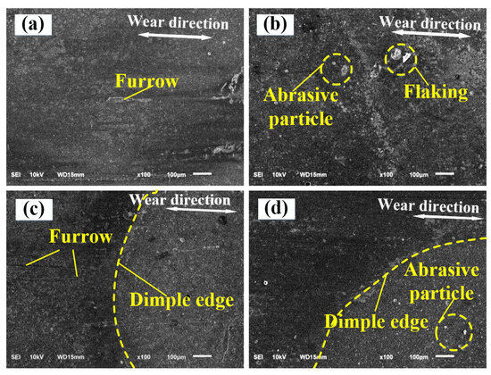
Figure 15.
Surface SEM of coatings after abrasion at various depths and 19.6% micro-modeling density: (a) 7.82 µm; (b) 14.52 µm; (c) 24.72 µm; (d) 31.39 µm.
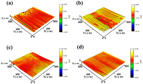
Figure 16.
Surface three-dimensional morphology of coatings after abrasion at various depths and 19.6% micro-modeling density: (a) 7.82 µm; (b) 14.52 µm; (c) 24.72 µm; (d) 31.39 µm.
In summary, the AlCrN coating on the surface of the micro-molded specimens was prepared in a manner that improved the wear resistance of the specimens. From the analysis of the surface wear morphology and considering the cost, the optimal process parameters for laser impact micro-molding lubrication are 19.6% micro-molding density and 24.72 µm pit depth, which is consistent with the results of Section 3.2.2.
3.4. Wear-Reducing Lubrication Modeling of Micro-Molding AlCrN Coatings
Figure 17a–d show the friction test process of a single-coated non-molded specimen, and Figure 18e–h show the friction test process of a micro-molded AlCrN-coated specimen.
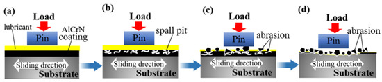
Figure 17.
Diagram of AlCrN coating wear-reduction lubrication process: (a) the initial stage of frictional wear; (b) the friction-wear stabilization stage; (c) the late stabilization stage phase; (d) the friction abrasion failure stage.
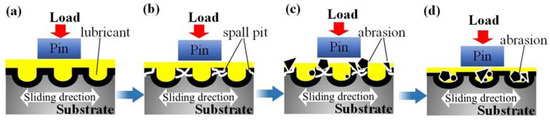
Figure 18.
Diagram of the micro-modeling and AlCrN coating’s synergistic wear reduction and lubrication process: (a) the initial stage of frictional wear; (b) the friction-wear stabilization stage; (c) the late stabilization stage phase; (d) the friction abrasion failure stage.
During the initial stage of frictional wear, the specimen’s surface was subjected to extrusion of the friction pins under load and the lubricant was adsorbed on the surface of both specimens, achieving friction-reducing lubrication through treatment of their respective surfaces (Figure 17a and Figure 18a).
During the friction-wear stabilization stage, for the single-coated non-molded specimen, the lubricant was quickly extruded by the friction pin, resulting in extrusion deformation and cracking of the coating surface (Figure 17b). In contrast, the micro-molded AlCrN-coated specimen relied on the high abrasion resistance of the micro-moldings and its oil storage function, maintaining good friction reduction and lubrication ability (Figure 18b). With increasing friction-test time, the flaking material on the surface of the single-coated non-molded specimen formed abrasive particles, which increased the friction and aggravated the damage to the coating surface (Figure 17c). However, in the micro-molded AlCrN-coated specimen, the lubricating oil in the micro-moldings was gradually consumed. Furthermore, a small number of abrasive particles were evident in the surface coating, along the sliding direction of the flaking and cracking, which fell into the micro-moldings, and the debris did not have a substantial influence on the coating (Figure 18c).
During the friction abrasion failure stage, the coating of the non-molded specimen was partially destroyed along the sliding direction, and the presence of a large number of abrasive particles as well as other debris exacerbated the destruction of the coating, leading to the failure of the specimen (Figure 17d). However, abrasive debris generated by the micro-molded AlCrN-coated specimen was collected by the micro-moldings, and geometric destruction of the micro-moldings was not obvious (Figure 18d).
By comparing Figure 17a–d and Figure 18a–d, it can be seen that the AlCrN coating exhibited high hardness, high wear-resistance, and a low coefficient of friction, which reduced friction and frictional heat generation. The array of micro-moldings provided a sufficient quantity of lubricant between the friction surfaces, yet also collected the abrasive particles and debris that were evident during wear, which were thereby kept from generating abrasive wear. In summary, preparing AlCrN coatings on laser-impact micro-molded surfaces improved the anti-wear performance of the tested metal surfaces.
4. Conclusions
- (1)
- The AlCrN coating prepared on a E690 high-strength steel surface by multi-arc ion plating was continuous and dense, with a uniform distribution of elements, no other impurities, and no obvious defects. Cross-sections exhibited a gradient layered structure, and an engineering bonding strength of 35 N; the interface between the coating and substrate exhibited good adhesion.
- (2)
- Compared with the micro-molding-only specimens, the micro-molded AlCrN-coated specimens exhibited decreases in the average friction coefficient and wear rate. The average friction coefficient of the various micro-molding densities was decreased by 4.38%, and the average wear rate was decreased by 35.19%. The specimens with a micro-molding density of 19.6% exhibited the lowest average friction coefficient, at 0.0936. When the micro-molding density was 19.6%, the micro-molded AlCrN-coated specimens exhibited a 5.1% reduction in the average friction coefficient and a 38.9% reduction in the average wear rate compared with the micro-molding-only specimens. Moreover, the AlCrN coating improved the stability of the friction process of the specimen. The best overall friction performance was achieved when the micro-molding density was 19.6% and the specimens underwent a single-point impact 3×, with the coefficient of friction reduced by 8.55% and the amount of wear reduced by 36.1%.
- (3)
- A synergistic wear-reduction lubrication model of micro-molding and AlCrN-coating was established to illustrate the interaction and wear reduction mechanism of the coatings under heavy loads as well as for oil lubrication. Compared with the model with only an AlCrN coating, the coating provided sufficient wear resistance for the specimen and the micro-moldings improved the oil storage capacity. Additionally, the coated specimens collected abrasive particles and debris in the micro-moldings, enhancing wear resistance and improving friction performance, thereby extending the wear life of the specimens.
Author Contributions
Conceptualization, Y.C.; Methodology, Y.C., H.B. and J.Z.; Validation, Y.C., W.S. and J.Z.; Resources, W.S. and Z.W.; Writing—original draft, H.B.; Writing—review and editing, Y.C., H.B., W.S. and J.Z.; Supervision, Y.C., Z.W. and J.Z.; Project administration, Y.C., W.S. and Z.W.; Funding acquisition, Y.C., W.S. and Z.W. All authors have read and agreed to the published version of the manuscript.
Funding
This work was supported by the National Key Research and Development Project of China: No. 2019YFB2005300; Nantong City livelihood project: MS22022040; the Project of Laser Processing and Metal Additive Manufacturing Technology and Application (SKJ2023-3); Ministry of Industry and Information Technology High-tech Ship Research Project: MC-202031-Z07; National Natural Science Foundation of China: No. 51505236; Postdoctoral Science Foundation of Jiangsu Province: 2021K606C.
Institutional Review Board Statement
Not applicable.
Informed Consent Statement
Not applicable.
Data Availability Statement
Not applicable.
Conflicts of Interest
The authors declare no conflict of interest.
References
- Syrek-Gerstenkorn, B.; Paul, S.; Davenport, A.J. Sacrificial Thermally Sprayed Aluminium Coatings for Marine Environments: A Review. Coatings 2020, 10, 267. [Google Scholar] [CrossRef]
- Hao, W.; Liu, Z.; Wu, W.; Li, X.; Du, C.; Zhang, D. Electrochemical characterization and stress corrosion cracking of E690 high strength steel in wet-dry cyclic marine environments. Mater. Sci. Eng. A 2017, 710, 318–328. [Google Scholar] [CrossRef]
- Li, K.; Yao, Z.; Hu, Y.; Gu, W. Friction and wear performance of laser peen textured surface under starved lubrication. Tribol. Int. 2014, 77, 97–105. [Google Scholar] [CrossRef]
- Zheng, L.; Zhang, C.; Zhang, C.; Dai, F. Performance of micro-dent array fabricated by laser shock peening on the surface of A304 stainless steel. Vacuum 2017, 138, 93–100. [Google Scholar] [CrossRef]
- Dai, F.; Geng, J.; Tan, W.; Ren, X.; Lu, J.; Huang, S. Friction and wear on laser textured Ti6Al4V surface subjected to laser shock peening with contacting foil. Opt. Laser Technol. 2018, 103, 142–150. [Google Scholar] [CrossRef]
- Aurelian, F.; Patrick, M.; Mohamed, H. Wall slip effects in (elasto) hydrodynamic journal bearings. Tribol. Int. 2011, 44, 868–877. [Google Scholar] [CrossRef]
- Etsion, I.; Sher, E. Improving fuel efficiency with laser surface textured piston rings. Tribol. Int. 2009, 42, 542–547. [Google Scholar] [CrossRef]
- Ryk, G.; Etsion, I. Testing piston rings with partial laser surface texturing for friction reduction. Wear 2006, 261, 792–796. [Google Scholar] [CrossRef]
- Mo, J.; Zhu, M. Sliding tribological behaviors of PVD CrN and AlCrN coatings against Si 3 N 4 ceramic and pure titanium. Wear 2009, 267, 874–881. [Google Scholar] [CrossRef]
- David, K.; Fu, G.; Wang, W.; Guo, H.; Zhang, L.; Ye, C. High Temperature Mechanical Behaviors of AlCrN Coatings Grown by Cathodic Arc Ion Plating. Chin. J. Vac. Sci. Technol. 2014, 34, 700–706. [Google Scholar] [CrossRef]
- Lin, Y.-J.; Agrawal, A.; Fang, Y. Wear progressions and tool life enhancement with AlCrN coated inserts in high-speed dry and wet steel lathing. Wear 2008, 264, 226–234. [Google Scholar] [CrossRef]
- Mo, J.; Zhu, M.; Lei, B.; Leng, Y.; Huang, N. Comparision of tribological behaviours of AlCrN and TiAlN coatings-Deposited by physical vapor deposition. Wear 2007, 263, 1423–1429. [Google Scholar] [CrossRef]
- Yuan, S.; Lin, N.; Zou, J.; Lin, X.; Liu, Z.; Yu, Y.; Wang, Z.; Zeng, Q.; Chen, W.; Tian, L.; et al. In-situ fabrication of gradient titanium oxide ceramic coating on laser surface textured Ti6Al4V alloy with improved mechanical property and wear performance. Vacuum 2020, 176, 109327. [Google Scholar] [CrossRef]
- Cao, Y.; Hu, R.; Shi, W.; Wang, Z.; Qiu, M.; Zhang, X.; Li, B. Experimental study on laser peen texturing and tribological properties of E690 high-strength steel. Opt. Laser Technol. 2023, 157, 108784. [Google Scholar] [CrossRef]
- Cao, Y.; Zhu, P.; Shi, W.; Hua, G.; Wang, H.; Qiu, M. Correlation between X-Ray diffraction pattern and microstructure of surface of E690 high-strength steel induced by laser-shock processing. Vac. Technol. Appl. Ion Phys. Int. J. Abstr. Serv. Vac. Sci. Technol. 2021, 195, 110595. [Google Scholar] [CrossRef]
- Mehran, Q.M.; Fazal, M.A.; Bushroa, A.R.; Rubaiee, S. A Critical Review on Physical Vapor Deposition Coatings Applied on Different Engine Components. Crit. Rev. Solid State Mater. Sci. 2017, 43, 158–175. [Google Scholar] [CrossRef]
- Jia, D.; Yi, P.; Liu, Y.; Jia, H.; Yang, X. Effect of the width and depth of laser-textured grooves on the bonding strength of plasma-sprayed coatings in the scratch direction. Mater. Sci. Eng. A 2021, 820, 141558. [Google Scholar] [CrossRef]
- Kimura, S.; Emura, S.; Tokuda, K.; Zhou, Y.; Hasegawa, S.; Asahi, H. Structural properties of AlCrN, GaCrN and InCrN. J. Cryst. Growth 2009, 311, 2046–2048. [Google Scholar] [CrossRef]
Disclaimer/Publisher’s Note: The statements, opinions and data contained in all publications are solely those of the individual author(s) and contributor(s) and not of MDPI and/or the editor(s). MDPI and/or the editor(s) disclaim responsibility for any injury to people or property resulting from any ideas, methods, instructions or products referred to in the content. |
© 2023 by the authors. Licensee MDPI, Basel, Switzerland. This article is an open access article distributed under the terms and conditions of the Creative Commons Attribution (CC BY) license (https://creativecommons.org/licenses/by/4.0/).