Article

Damage Grading Evaluation of Thermal Barrier Coatings under CMAS Corrosion

1
Key Laboratory of Pressure System and Safety, Ministry of Education, East China University of Science and Technology, Shanghai 200237, China
2
AECC Commercial Aircraft Engine Co., Ltd., Shanghai 200241, China
*
Authors to whom correspondence should be addressed.
Coatings 2023, 13(9), 1495; https://doi.org/10.3390/coatings13091495
Submission received: 3 August 2023 / Revised: 17 August 2023 / Accepted: 23 August 2023 / Published: 24 August 2023

Abstract

:
Thermal barrier coatings (TBCs) material has excellent high-temperature resistance and heat insulation performance, which plays a vital role in improving the working efficiency and running life of the engine. During the flight, the engine will inhale dust particles in the air. These particles are mostly from siliceous debris, which are usually called calcium magnesium aluminum silicate (CMAS). At present, CMAS corrosion has become one of the important problems affecting the service life of thermal barrier coatings. In this study, conventional yttrium oxide stabilized zirconia (YSZ) coatings and ytterbium oxide and yttrium oxide co-stabilized zirconia (YbYSZ) coatings were prepared by atmospheric plasma spraying. The two coatings were examined under thermal cycling-CMAS coupling conditions and divided into six life stages. The failure modes, CMAS permeation behavior, crack characteristics and mechanical properties of the two coatings at different life stages were evaluated systematically. The experimental results show that the YbYSZ coating has a longer life than YSZ coating under the thermal cycling and CMAS coupling condition, which increases by about 83% compared with the conventional YSZ coating. In the whole life stage, the porosity of YbYSZ coating is always higher than that of YSZ coating. The phase transition is not the reason for the failure and spalling of the coatings. The crack length of the two coatings showed an increasing trend, but the crack length of the YSZ coating was higher than that of the YbYSZ coating, and the crack density of the two coatings showed a “saddle shape”, which was more obvious for the YSZ coating. The YbYSZ coating shows better mechanical properties under the thermal cycling-CMAS coupling condition with the evolution of life.

1. Introduction

Thermal barrier coating (TBCs) has been widely used in high-temperature components of ground gas turbines and aero engines. As one of the essential core technologies of aero-engine turbine blades, TBCS are used to block the direct contact between metal components and high-temperature gas. Its excellent thermal insulation performance can isolate metal components from hot gas and effectively protect substrate materials. Thus, the working temperature and the efficiency of the engine is improved [1]. TBCs usually consist of bond layers and ceramic layers. The commonly used coating material is yttrium-stabilized zirconia (YSZ) [2].
The preparation technology of the thermal barrier coating is a key factor affecting the microstructure of the coating, which in turn affects the service performance of the coating. Therefore, according to different application scenarios and functions, the microstructure and properties of the coating can be regulated by different preparation processes. At present, the common preparation technologies of thermal barrier coating include Atmospheric Plasma Spraying (APS) and Electron Beam-Physical Vapor Deposition (EB-PVD). In addition, thanks to the development of coating preparation technology and spraying equipment in recent years, based on Plasma Spraying technology and physical phase deposition technology, Suspension Plasma Spraying (SPS) and Solution Precursors Plasma Spraying have also been developed, along with SPPS and Plasma Spray-Physical Vapor Deposition (PS-PVD) and other new coating preparation technologies [3]. At present, the above new thermal barrier coating preparation technologies are still in the laboratory research stage and have not been applied in industrial production. Because the APS has the characteristics of a wide range of applicable materials, strong function, high bonding strength, good heat insulation performance and high efficiency, the coating is prepared by APS in this experiment.
The melting point of CMAS is primarily between 1190 and 1260 °C. At the same time, it also has excellent wetting ability [4]. With the continuous increase in engine operating temperature, the deposition of CMAS has become one of the challenges in the service of traditional thermal barrier coatings. The former greatly impacts on the durability of thermal barrier coatings and seriously affects the working efficiency and service life of turbine engines. The mechanism of CMAS leading to TBCs failure is as follows: (1) At high temperatures, the CMAS melt will be deposited on the surface of TBCs and infiltrate into the porous structure of the ceramic layer. The brittle glass phase generated during cooling dramatically reduces the strain tolerance of the coating [5]; at the same time, the penetration of CMAS into the ceramic layer will affect the coating density and increase thermal conductivity. (2) Because the solubility of Y3+ in CMAS melts is greater than that of Zr4+, YSZ phase transition instability will be caused [6]. (3) When CMAS penetrated into the ceramic layer and reached the surface of the Thermally Growth Oxide (TGO) layer, chemical reactions occurred with the coating, which accelerated the peeling failure of the coating on TGO. With global environmental deterioration, such as volcanic eruptions and dust storms, CMAS corrosion has been recognized as a serious concern of the global public [7].
In order to alleviate the erosion of TBCs by CMAS sediments, relevant studies have been carried out at home and abroad [8]. The main research directions at present are: (1) non-wetting thermal barrier coating, which can minimize the non-wetting of molten CMAS and the contact between coating and melt; (2) dense non-permeable thermal barrier coating, which is continuous, dense and crack-free to prevent melt penetration from the physical layer [9]; and (3) sacrificial thermal barrier coating, which can chemically react with CMAS components to produce substances with a high melting point or peel off after reaction, playing a protective role [10].
Most of the existing studies are carried out by CMAS constant temperature corrosion experiments, and there are few kinds of studies on evaluating the service capability of TBCs under the thermal cycle-CMAS coupling condition. Meanwhile, there are few studies on the relationship between various critical indexes of coating in the service process, such as crack density, crack length, CMAS penetration depth, and so on, with the number of thermal cycles. To this end, the conventional YSZ coating and ytterbium oxide and yttrium oxide co-doped zirconia coating (YbYSZ) were tested on a gas thermal shock test bed. The composition and microstructure evolution of the thermal barrier coating under complex service conditions of thermal cycling-CMAS coupling was studied by dividing the life stages of the two coatings. Based on the mechanical properties of thermal barrier coatings, the relationship between the evolution of composition and microstructure and the properties of thermal barrier coatings was established in the corrosion–thermal cycling interaction process. The damage variation in the whole time domain is useful to realize the prediction of the residual life of thermal barrier coating in the thermal cycling–corrosion environment.

2. Experiments

2.1. Coating Preparation

In this study, the conventional YSZ coating and YbYSZ coating were prepared by atmospheric plasma spraying (APS) technology. The spraying equipment used for the preparation of the coating is APS-2000 spraying equipment produced by Oerlikon Metco. This experiment needs to form a temperature gradient inside the sample and reach a high temperature of 900 °C on the back of the sample. Therefore, the substrate used in this experiment is GH-5188, which is a Co-Ni-Cr-based solid solution strengthened deformation superalloy. It takes carbide as the main strengthening phase and its melting temperature range is 1300–1360 °C. GH-5188 is manufactured by China Aviation Technology International Holdings Limited with a size of phi25.4 × 6.35 mm. To improve the bonding strength, sandblasting is carried out first, followed by ultrasonic cleaning. Prior to the deposition of the ceramic layer, NiCrAlY bond coating (BC) was sprayed on the sandblasted substrate. The specific parameters of spraying are shown in Table 1. In previous studies [7], only the effect of coating resistance to CMAS corrosion was considered without thermal shock. The parameters in Table 1 are determined through continuous trial and error and combined with the properties of the material itself, such as melting point, to comprehensively improve the corrosion resistance of CMAS and thermal shock resistance.
The spraying powders used in this experiment are all commercial powders manufactured by third parties. YSZ powder is manufactured by Beijing Sunspraying Technology Co., Ltd., Beijing, China. YbYSZ powder is manufactured by Suzhou Meierbang Material Co., Ltd., Suzhou, China. The same granulation process prepared the two powders used in the ceramic layer. Both powders were sintered in solid phase with commercial powders followed by spray drying to obtain hollow agglomerated powders with similar particle size ranges. And the two different zirconia powders accordingly stabilized with 4.5% Y2O3 and 4.0% Yb2O3–0.5% Y2O3 (mol.%). Figure 1 shows the microscopic electron microscopy and particle size distribution of YSZ powder and YbYSZ powder. The morphology of the two powders is the same in the form of subspherules or erythrocytes. The XRD patterns of the two powders show that the two powders have the same phase structure. The particle size range of the two powders is about 10~60 μm, and D50 is about 25~30 μm.

2.2. Thermal Cycling-CMAS Test

In this experiment, all the oxide powders required for CMAS preparation were made by Sinopharm Chemical Reagent Co., Ltd., Beijing, China. In this study, a gas flame impact thermal shock test platform was used to evaluate the thermal barrier coating system’s durability in a harsh environment. Unlike the heat cycle experiment in the furnace, the gas flame impact test conditions were more stringent and closer to the actual service conditions of coatings. In this experiment, high-temperature gas generated by the combustion of propane and oxygen is used to rapidly heat the coating surface of the sample, while the back of the sample is continuously cooled by compressed air, thus forming a very high-temperature gradient inside the thermal barrier coating system, and then simulating the service condition of the thermal barrier coating system in the aero engine combustion chamber [8,9]. At the end of the heating stage, the turntable holding the sample will rotate to the cooling station, and the compressed air will quickly cool the surface and back of the sample, making the sample temperature drop to 100 °C within 60~80 s. This way, two opposite temperature gradients can be generated within the thermal barrier coating system. The sample’s surface temperature and internal temperature gradient can be controlled by adjusting the propane/oxygen flow ratio, the distance between the flame gun and the sample surface and the compressed air flow rate. In this study, the coating surface temperature is controlled at about 1300 °C, and the sample substrate back temperature is about 900 °C. For the cycling-CMAS coupling service conditions simulation, each cycle consisted of 5 min flame heating and 5 min compressed air cooling. After every two thermal cycles, a pre-configured 8 wt.% CMAS alcohol slurry was evenly coated on the coating surface with a soft brush. By comparing the sample quality before and after coating, it can be seen that each coating can increase the coating surface CMAS concentration by about 1.2 mg/cm2, and the criterion of coating failure is 20% cracking or peeling of the coating.

2.3. Characterization

The microstructure and morphology of the coatings were observed using a scanning electron microscope (SEM, Hitachi S-3400N, Hitachi, Tokyo, Japan) equipped with a backscattered electron (BSE) detector. In addition, the energy dispersion spectrometer (EDS) configured in the SEM was used to determine the penetration depth of CMAS melt in the coating. X-ray diffraction spectrometer (XRD, D/max, 2550 VB/PC, RIGAKU, Tokyo, Japan) was used to characterize the phase composition of the samples before and after failure. The diffraction angle range was 10–80°. The micro elastic modulus and hardness of the coating were measured by the indentation method, the load of which was 300 gf and the loading time was 15 s. The microhardness and elastic modulus of the coating can be obtained by indentation method, and the test locations are randomly and evenly distributed in the CMAS penetration region. The Vickers hardness tester used in the test is HXD-1000TMC/LCD, and its manufacturer is Shanghai Taiming Optical Instrument Co., Ltd., Shanghai, China. The test position of the indentation was randomly distributed inside the coating.

3. Results and Discussion

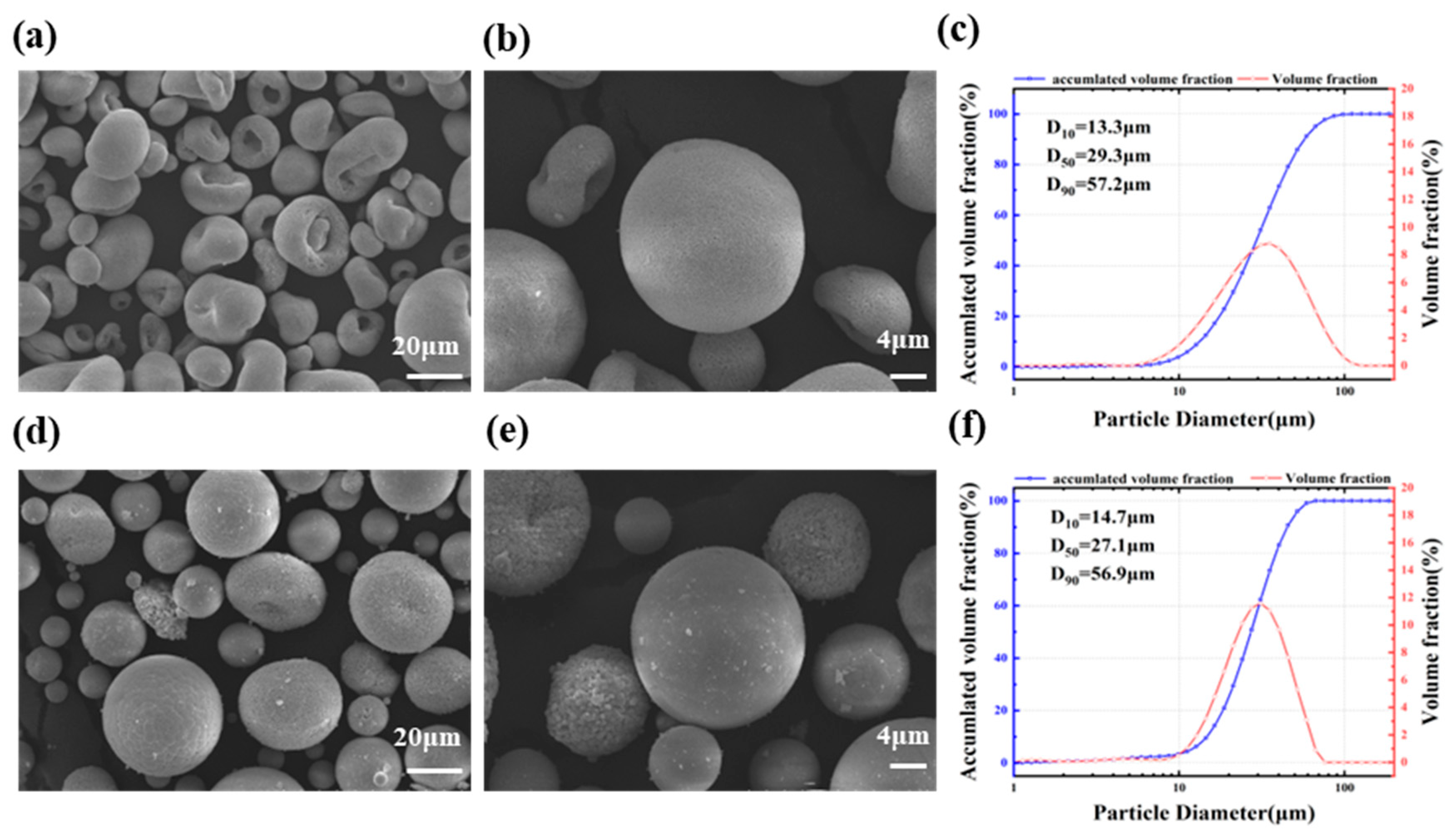
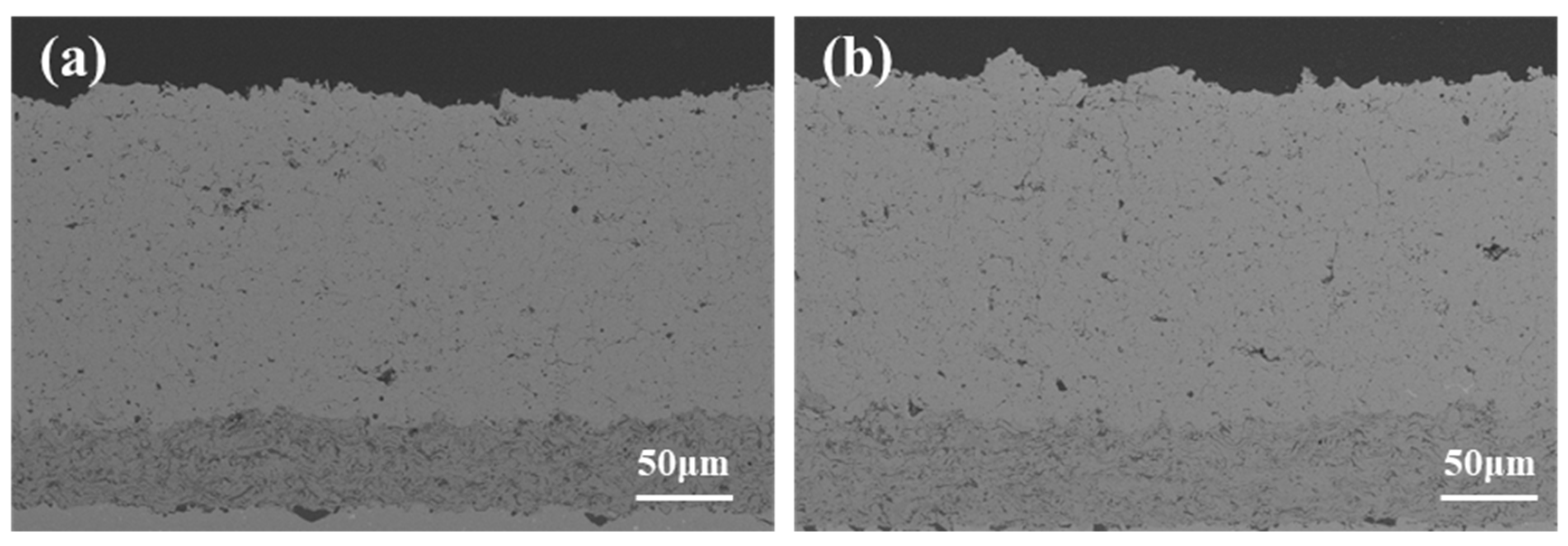
3.1. Microstructure Analysis of Coatings

The microstructure of the two sprayed coatings is shown in Figure 2. The microstructure has typical APS characteristics, such as incomplete melted particles, micro cracks and pores parallel to the ceramic/substrate interface. On the one hand, due to the internal defects of the coating perpendicular to the direction of heat flow, the thermal insulation performance of coatings is greatly improved. On the other hand, the microstructure of coatings will affect the penetration rate of molten CMAS [11]. The pores and cracks in sprayed coatings significantly improve the permeability of CMAS to coatings, and vertical cracks are the key factors in determining the penetration depth of CMAS.

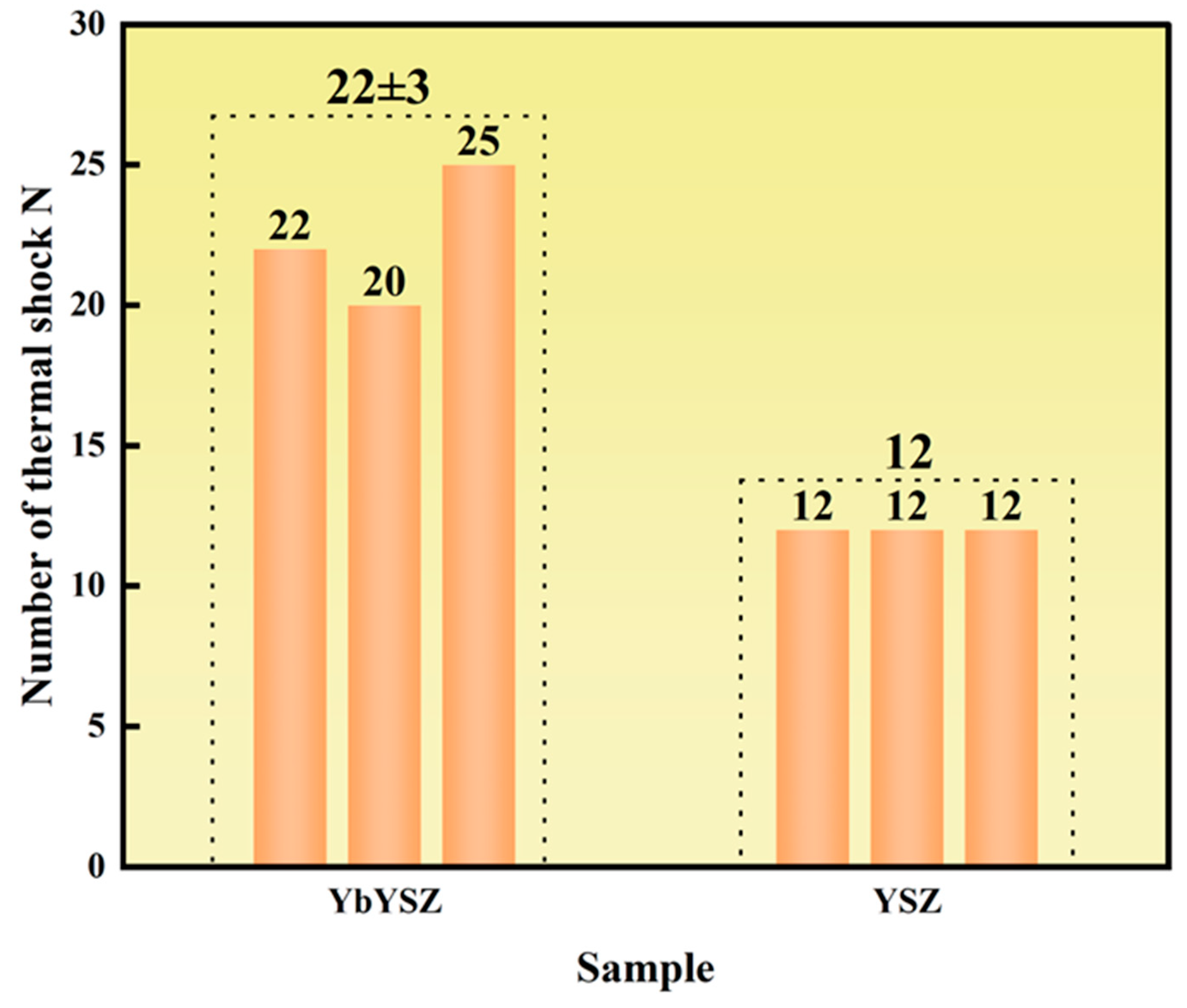
3.2. Life Comparison under Thermal Cycling-CMAS Coupling Condition

Figure 3 compares the life of the two thermal barrier coatings under thermal cycling–CMAS coupling conditions. As can be seen from the figure, thanks to the incorporation of Yb3+, YbYSZ presents a better performance. The thermal cycle life of YbYSZ coating is 22 ± 3 times compared with 12 times of YSZ coating, and the lifetime of the YbYSZ coating is improved by about 83%. According to a previous study [7], under the same coupling conditions, the thermal cycle life of DCL-YbYSZ is increased by 33% and 120%, respectively, compared with that of DCL-YSZ and conventional YSZ. By comparing DCL-YbYSZ and DCL-YSZ by a single variable method, it can be found that the doping of Yb improves the ability of the coating to resist the coupling condition of CMAS–thermal shock. On the other hand, by comparing DCL-YSZ with conventional YSZ, it can be found that the structure also has a great influence on the ability of coating to resist coupling conditions. In this paper, the structure of the single layer coating is optimized from the spraying parameters, so that the life of the YbYSZ coating is increased by 83% compared with the traditional YSZ. This also shows that in the subsequent research, more attention should be paid to improving the ability of coating to resist coupling conditions through structural optimization. The average life of the coating was divided into six stages, and the cycles of each stage (I~VI) of the YSZ coating were 2, 4, 6, 8, 10, and 12, respectively. The cycles of YbYSZ coating at each life stage are 3, 7, 11, 15, 19 and 22, respectively. By analyzing the performance of the coatings under thermal cycling–CMAS coupling condition, it can be concluded that YbYSZ coating shows better performance than YSZ coating under coupling condition.

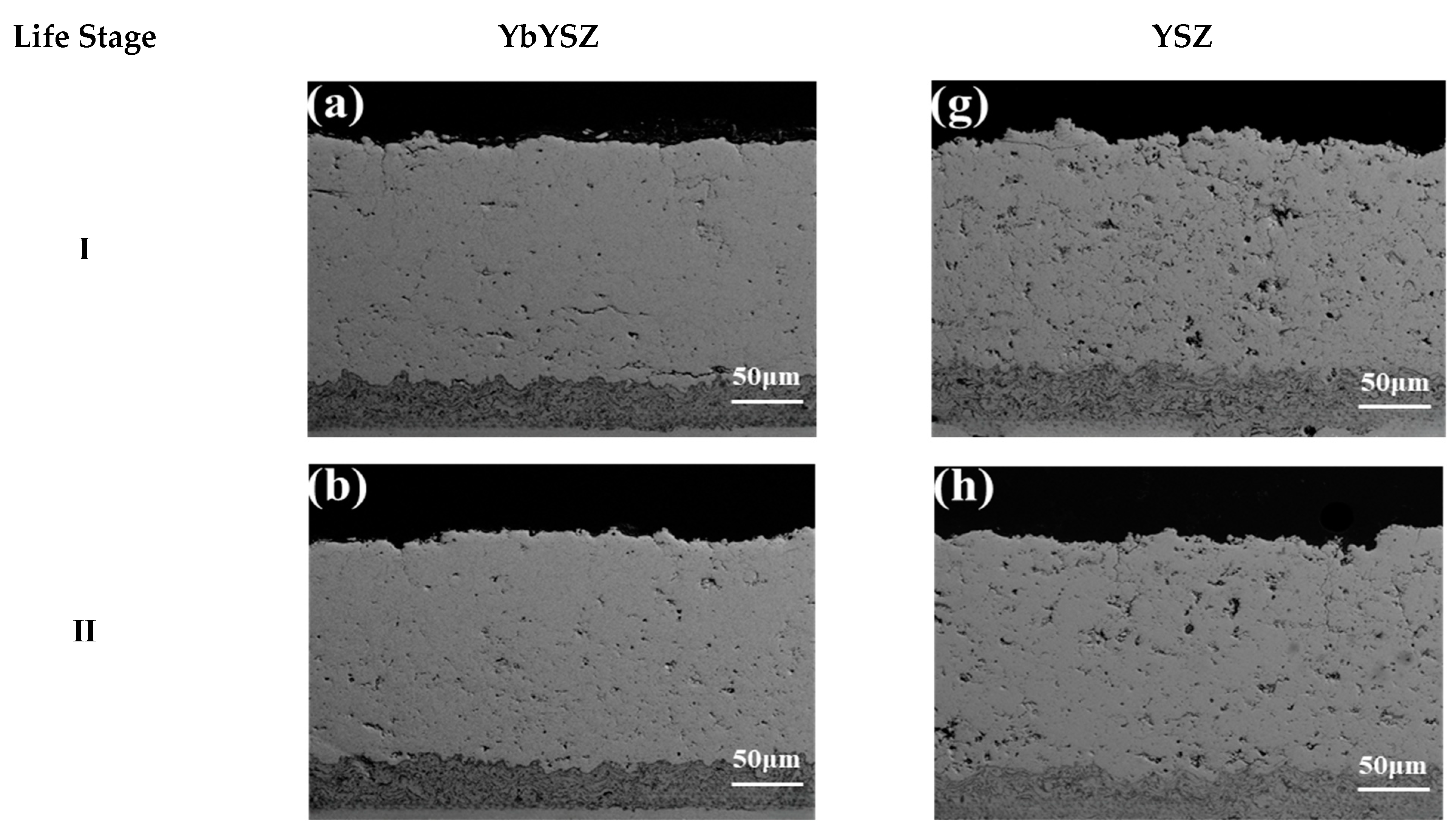
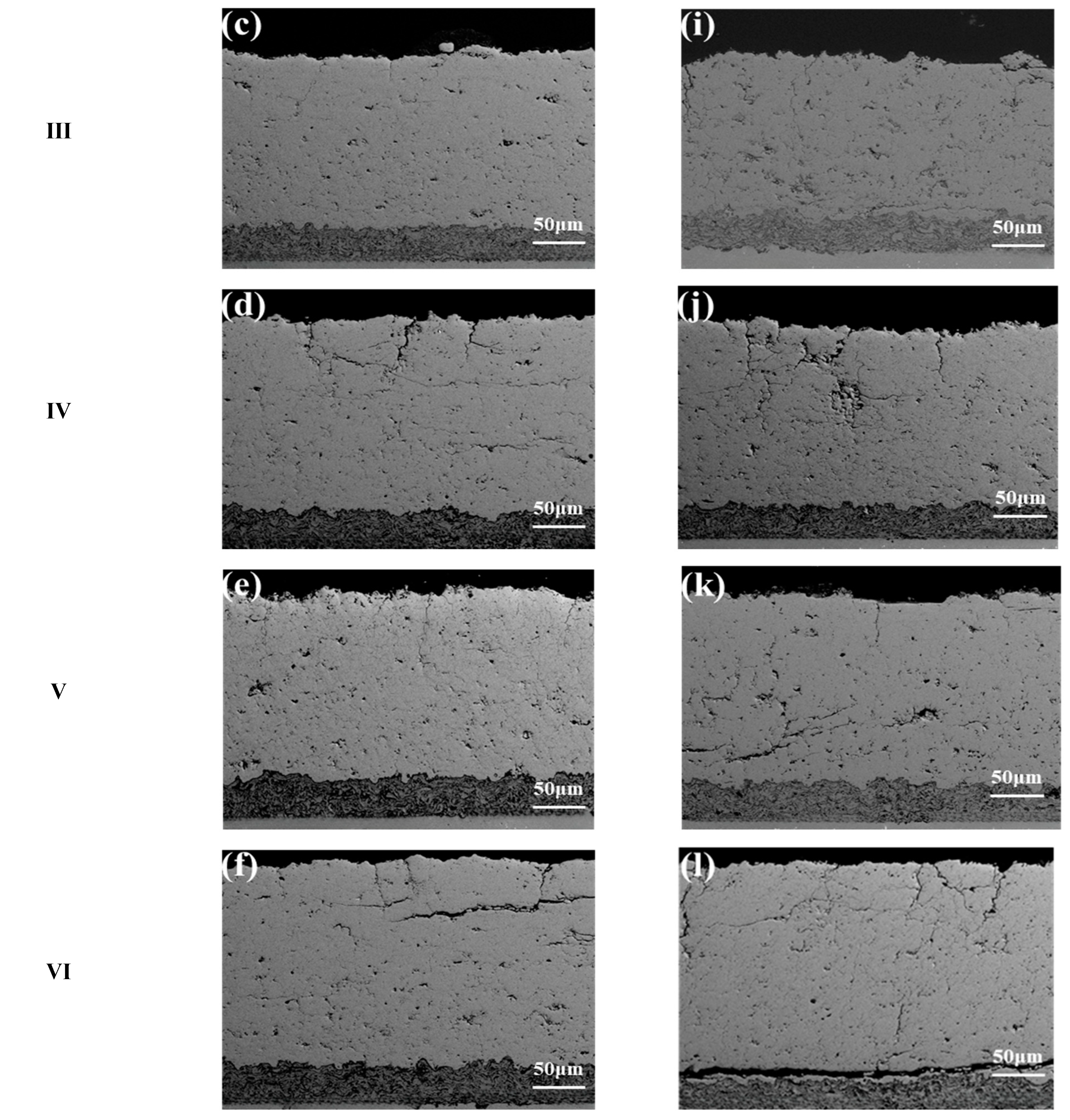
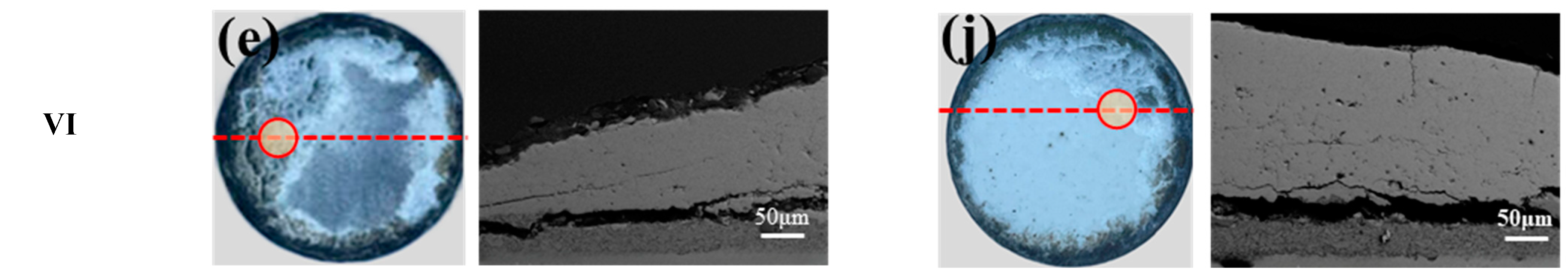
3.3. Failure Analysis of Thermal Cycling-CMAS Coupling Condition

Observing the cracking behavior of coatings is an essential means to trace the coating failure and explain the failure mechanism. Figure 4 shows the macroscopic morphologies of the YSZ coating and the YbYSZ coating at different life stages and the microscopic morphologies at the failure point under coupling conditions. Because of the edge effect [12], the peeling of the coating originated from the edge of the sample and gradually extended to the center of the coating. This is similar to what has been observed in other studies. There are many reasons for the edge effect of coating during thermal shock, which involves many fields such as heat, mechanics, and material science. First, there may be differences in the coefficient of thermal expansion between the coating material and the substrate, resulting in thermal expansion mismatches caused by temperature changes during thermal shock. This causes high thermal stress at the edge of the coating, which may lead to peeling and cracking of the coating. Secondly, due to the large thermal inertia of the coating edge, the response of the coating edge during thermal shock is different, resulting in more drastic changes in the temperature gradient and stress distribution in the edge region. In addition, the coating will form an edge on the substrate, which will cause the heat conduction and stress distribution in the edge area to be different from the rest of the coating surface, increasing the occurrence of edge effects. Finally, during thermal shock, periodic changes in temperature may cause the coating edge region to experience more frequent thermal expansion and contraction, further aggravating thermal stress and thermal fatigue effects [13]. With the increase in thermal shock times, the peeling area of the coating increases. It is not difficult to see that at the same lifespan stage, the YbYSZ coating peels off less than the YSZ coating, exhibiting strong resistance to thermal cycling CMAS coupling conditions. It can be seen from the microstructure diagram of the coatings peeling place that the coating has obvious thinning at the peeling place. Even in the stage III and IV, the surface of the thinning coating presents a stepped structure. At the last life stage of the two coatings (the V and VI life stages), it can be found in the microscopic image of the coating failure site that the interface of BC layer and TC layer has a long horizontal crack. This is due to the thermal mismatch between the ceramic layer and the metal matrix. During the thermal cycling process, a large thermal stress will be formed near the interface of the ceramic layer/bonding layer, and the coating damage will continue to accumulate during the thermal cycling process, and eventually a penetrating horizontal crack will be formed, resulting in a large area of the coating peeling. The formation of this horizontal crack is the leading cause of coating failure, and this kind of failure form is also one of the most common failure forms of thermal barrier coatings. When molten CMAS permeates into the pores of the coating at high temperature, the thermal mismatch of the coating is aggravated. The level of elastic modulus and elastic strain energy of the coating was increased during cooling and curing. In addition, liquid phase sintering accelerates the coarsing and densification of laminate particles, resulting in a rapid increase in the elastic modulus of the coating and deterioration of mechanical properties. In the process of thermal cycling–CMAS examination, it is due to the infiltration of melt that the lamellar spalling of the coating surface is caused.
Figure 5 shows the microstructure of coatings at different life stages under the thermal cycling–CMAS coupling condition. The porosity of the coatings decreases significantly after the thermal cycling–CMAS coupling condition, which is caused by sintering in the thermal shock process. At the same time, many layered cracks parallel to the surface are formed in the ceramic layer at different depths. This is because after the coating permeated by CMAS is cooled, a considerable cooling stress is generated [14], resulting in increased density and brittleness and cracking. The rapid propagation of the delamination crack leads to the fragmentation of the coating near the surface. With the continuous development of the life stage, there are more vertical cracks in the coatings, and these cracks will become the main channels for the infiltration of CMAS melt. The cause of vertical cracks is that in the process of rapid cooling, due to the thermal mismatch between the coating and substrate intensified by CMAS penetration, the coating surface will generate sizeable tensile stress, which induces vertical cracks along the thickness direction. The above two kinds of cracks connect and expand with the evolution of coating life and eventually lead to the peeling and failure of the coatings.
The spalling or thinning of the coating surface mainly causes the failure of the thermal barrier coating prepared by atmospheric plasma spraying. The crack evolution process of the thermal barrier coating during the thermal cycle is directly related to the spalling of the coating [15]. The information of cracks in the coating is obtained statistically from all cracks observed in the cross-section of the specimen. When calculating vertical cracks, the coating structure image was continuously taken along the coating cross-section by electron microscope under 100× lens, and the length and number of vertical cracks on the entire coating cross-section of the sample were counted. To avoid the influence of cracking caused by the edge effect on the statistical results of cracks inside the coating, only the cracks in the 12.7 mm length area at the center of the coating cross-section are counted, and the statistical range is about half of the diameter of the coating sample. Most of the cracks in the coating are of non-specification shape, and the statistical value of the crack length is the length of the vertical crack projected in the direction parallel to the matrix. The cracks in the coating are approximately evenly distributed in the cross-section, so the crack density of each sample is obtained by comparing the number of cracks in the statistical region with the length range of the statistical region. The effect of gas thermal shock on crack length and crack density of coatings is shown in Figure 6. In the initial stage, the average crack length of the YbYSZ coating is higher than that of the YSZ coating. This is because the YbYSZ coating is doped with ytterbium element compared with the YSZ coating, which increases the crystallinity of the coating to a certain extent, making it more difficult for the YbYSZ coating to form a tight structure during heat treatment. As a result, there may be more small holes and longer cracks at the grain boundaries, resulting in longer cracks length than the YSZ coating. The average crack length increases with the increasing number of thermal shock and infiltration of CMAS. In all life stages, it is evident that the crack length of the YbYSZ coating is smaller than that of the YSZ coating. Even in the final life stage, the average crack length of the YSZ coating is 115.83 ± 13.5 μm, while that of the YbYSZ coating is only 91.70 ± 10.7 μm, which is reduced by about 21%.
In the initial life stage (the I and II life stages), the crack density of the two coatings decreases slightly, and the crack density of the YSZ coating is slightly higher than that of the YbYSZ coating. Meanwhile, it can be seen from the changing trend that the YSZ coating shows a more apparent sintering effect. In this stage, the mean crack length of the YSZ coating increases while the mean crack length of the YbYSZ coating decreases. With the increasing number of thermal shock and the continuous infiltration of CMAS, the crack density of the two coatings showed a “saddle shape”. Compared with the conventional YSZ coating, the YbYSZ coating shows a more prominent trend.
The crack is a two-dimensional feature, while the crack statistics are one-dimensional. When these cracks extend to the entire diameter, cracks near the diameter of the section will be observed [16]. The increase in crack density in the coating section during the thermal cycle reflects the rapid propagation of cracks in the coating or the initiation of new cracks near the coating section. The decrease in crack density in the late thermal cycle reflects the combination of cracks in the coating. When many cracks in the coating combine, the coating will flake off quickly and fail [17]. The crack density of the two coatings increased rapidly in the II to IV life stage and reached the maximum value in the IV life stage, indicating that the cracks in the coating expanded quickly during this process, and many cracks were observed in the section. In this process, the increasing length of cracks also reflects that the cracks in the coating are in the active growth stage. After the IV life stage, the crack density showed a decreasing trend, indicating that more and more cracks merged in the coating, but the growth rate of crack length of the two coatings did not change significantly, which may be due to the short thermal fatigue life of the coating and the fewer thermal shock times [18].
The porosity was measured from the entire area of the coating without cracks formed in the thermal cycling process, which was obtained by Image analysis. The 200× ceramic layer image taken under the optical microscope was processed by Image-J2 software to obtain the porosity of the coating. In image processing, a suitable threshold is set for image segmentation, the pore structure in the image is extracted and converted into a binary image, and the coating porosity is obtained by calculating the ratio of the pore pixels in the image to the total pixels in the image. To obtain accurate statistical results, the porosity of each sample was calculated from the measurement results of 10 coating images. The influence of thermal shock on the porosity of the two coatings at different life stages is shown in Figure 7. In the spray state, the porosity of the YbYSZ coating is about 36% higher than that of the YSZ coating, and the reasons have been explained in the crack characteristics analysis part, so we will not go into details here. In the whole life stage, the porosity of the two coatings showed a decreasing trend, but the porosity of the coating prepared by YbYSZ powder was always higher than that prepared by YSZ powder. This is because Yb3+ has a larger atomic mass during the process of grain growth, so it has a slower diffusion rate, which also indicated that the YbYSZ coating had better sintering resistance than the YSZ coating. The pore structure of coatings is an essential factor affecting its thermal cycle life. Many experimental and simulation studies in the literature have also shown that coatings with large porosity have better strain tolerance and, thus, better thermal shock resistance [19].
During the service process of thermal barrier coating, its cracking is mainly closely related to zirconia phase transition [20], thermal stress mismatch [21], TGO growth [22] and high-temperature sintering behavior [23]. As shown from the XRD results of different life stages in Figure 8, the phase structure of the two coatings in each life stage is consistent, and they are all single tetra phase. Previous studies have shown that the phase transition from t-ZrO2 to c-ZrO2 and m-ZrO2 exists only when the temperature is 1300 °C and the sintering time is more significant than 150 h, especially the transition from t-ZrO2 to m-ZrO2 [24]. In addition, it has been proved that the high-speed cooling rate can inhibit the phase transition of zirconia coatings [25]. In this experiment, the total thermal exposure time of the coating at high temperature is short, and the rapid cooling of the coating surface by compressed air during the sample cooling process does not meet the favorable conditions for promoting phase transformation. According to previous studies [26,27], relatively high concentrations of impurity oxides, especially SiO2 and Al2O3, can generate segregation at the grain boundary by enhancing diffusion at the grain boundary and promoting sintering of the coating. In this experiment, phase transformation is not an influential factor for coating failure under thermal cycling-CMAS coupling conditions, but the filling pores and accelerated sintering caused by CMAS are the main reasons for coating failure.

3.4. Mechanical Properties Analysis

The hardness and elastic modulus of the coating are shown in Figure 9. The hardness of the YbYSZ coating and the YSZ coating showed an increasing trend with the increase in the number of thermal cycles, and the hardness increased by 15.0% and 19.4%, respectively, which was caused by the decrease in the coating porosity under the action of sintering. In addition, the heating and cooling processes in the thermal cycle would cause changes in the thermal stress and residual stress inside the coating. Due to the difference in coefficient of thermal expansion, the coating will be subjected to compressive stress. As the thermal cycle progresses, these residual stresses will gradually accumulate, resulting in an increase in the hardness of the coating. In the I life stage, the hardness of the YbYSZ coating is higher than that of the YSZ coating. Thanks to the doping of rare earth element Yb3+, the mechanical properties of the YbYSZ coating are improved [26]. The increase in hardness can improve the erosion resistance of the thermal barrier coating, thus increasing its service life [27]. In the remaining life stage, the hardness of the YbYSZ coating is lower than that of the YSZ coating, which is due to the better sintering resistance of the YbYSZ coating, which provides more pores for the infiltration of more CMAS, and the hardness of the glass phase generated after cooling is lower, thus reducing the average hardness of the YbYSZ coating.
The elastic modulus of the YbYSZ coating and the YSZ coating showed a trend of increasing first (I~V) and then decreasing (V~VI), and the elastic modulus increased by 56.9% and 22.8%, respectively, during failure. The reason for this change was that molten CMAS penetrated into the coating pores at high temperature, which aggravated the thermal mismatch of the coating. The level of elastic modulus and elastic strain energy of the coating was increased during cooling and curing. In addition, CMAS liquid phase sintering accelerates the coarsing and densification of laminate particles during the thermal cycle, which is also an important reason for the increase in the elastic modulus of the coating. At the same time, due to the periodic heating and cooling of the coating, the residual stress gradually accumulates. This stress accumulation can lead to changes in the microstructure of the material in the coating, the arrangement of atoms inside the coating becomes closer, and the interaction between atoms increases, so that the elastic modulus of the coating will increase at the beginning of the thermal cycle. Under the action of thermal cycling for a long time, the coating will also appear fatigue damage, resulting in cracks and peeling of the coating. At the same time, these damages will lead to the local stress concentration of the coating and the fracture of the material, and then the elastic modulus of the coating will show a downward trend. Combined with the porosity change of the two coatings, the accelerated sintering caused by CMAS penetration will lead to the increase in elastic modulus and the degradation of the thermal insulation performance of the coating, which will adversely affect the reliability and durability of the thermal barrier coating system [28]. When the elastic modulus is large, the thermal strain resistance of the coating during the thermal cycle will be reduced, and the thermal mismatch stress level will be significantly increased, thus leading to premature failure of the coating. Combined with the experimental results, the hardness and elastic modulus of the YbYSZ coating is smaller than that of the YSZ coating in most life stages, so the former can maintain relatively good mechanical properties under coupling conditions.
Combined with the crack evolution behavior of the coatings at different life stages, the evolution of the mechanical properties of the two coatings does not form a corresponding trend with the crack evolution behavior. Therefore, it can be considered that the main influencing factor related to the evolution of the mechanical properties of the coatings in this experiment is not the crack evolution behavior, but the sintering behavior of the coatings. In the sintering process, the porosity of the coating material is reduced, which will make the coating denser, thus improving the hardness and elastic modulus of the coating.
In this paper, the performance and structure evolution of the two coatings under thermal cycling-CMAS corrosion coupling were studied and compared from the life stage of the coating, to achieve the life prediction. However, this paper only studied the service ability of the coating under this specific working condition and did not make a more detailed study on other aspects, such as erosion resistance and marine corrosion. In addition, future research directions should focus on the design optimization of coatings and continue to explore the design of multi-layer coating structures, including the combination of different materials and functional layers. By introducing different layers into the coating, the blocking effect of the coating on CMAS erosion is increased. At the same time, how to regulate the pore structure and porosity of the thermal barrier coating to slow down the penetration rate of CMAS, to delay the failure process of the coating.

4. Conclusions

In this study, the gas thermal shock test platform was used to simulate the thermal cycling–CMAS coupling condition of the coating in actual service. The life stages of two different plasma-sprayed thermal barrier coatings were divided under the coupling condition, and the cycle life, failure mode and CMAS permeation behavior of the coating were experimentally studied. The following conclusions can be drawn from the current work:
(1)
The YbYSZ coating shows excellent performance under thermal cycling and CMAS coupling conditions, and its life is about 83% longer than that of the conventional YSZ coating. Due to boundary effects, the peeling of the coating originates at the edge and gradually spreads to the center of the specimen in both coatings. In the V and VI life stages, a horizontal penetrating crack near the BC/TC interface was found, which was the leading cause for the coating failure.
(2)
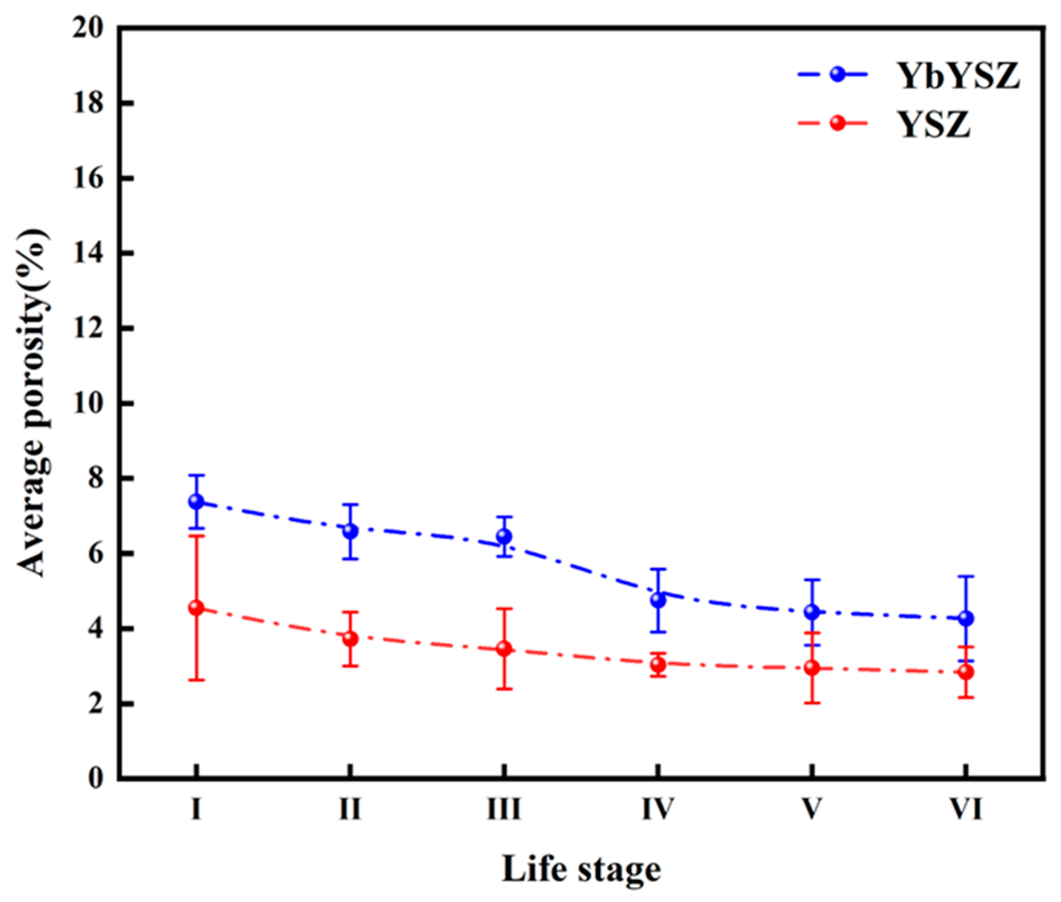
The porosity of the YbYSZ coating is always higher than that of the YSZ coating in the whole life stage, showing relatively good sintering resistance. The XRD pattern shows that the main reason for coating failure is not phase transition but the decrease in strain tolerance and heat insulation properties caused by CMAS filling pores and accelerated sintering.
(3)
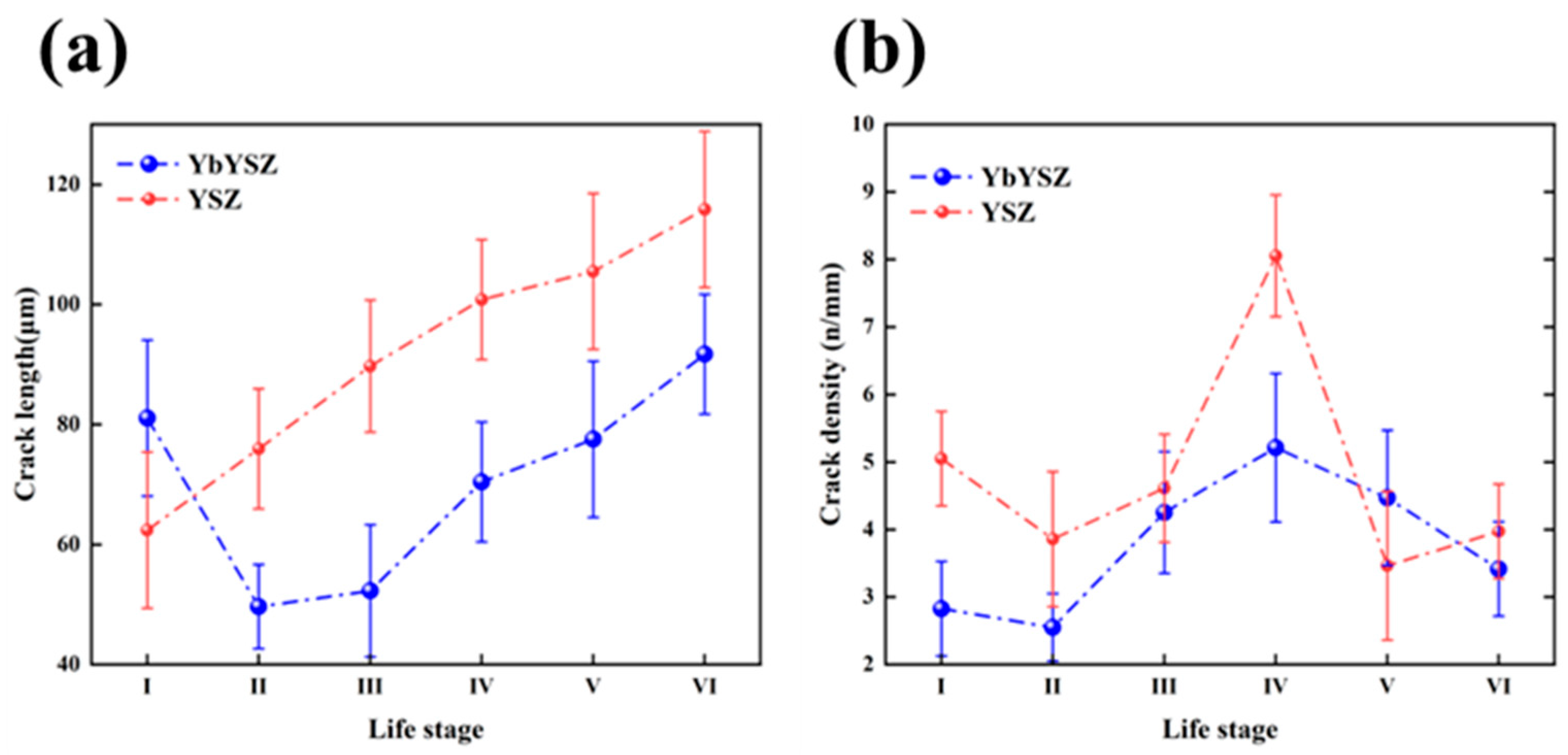
Under the thermal cycle–CMAS coupling condition, the crack length of the two coatings increases, but the crack length of the YSZ coating is higher than that of the YbYSZ coating except at the I life stage. The crack density of the two coatings showed a “saddle shape”, and the YSZ coating showed a more prominent trend.
(4)
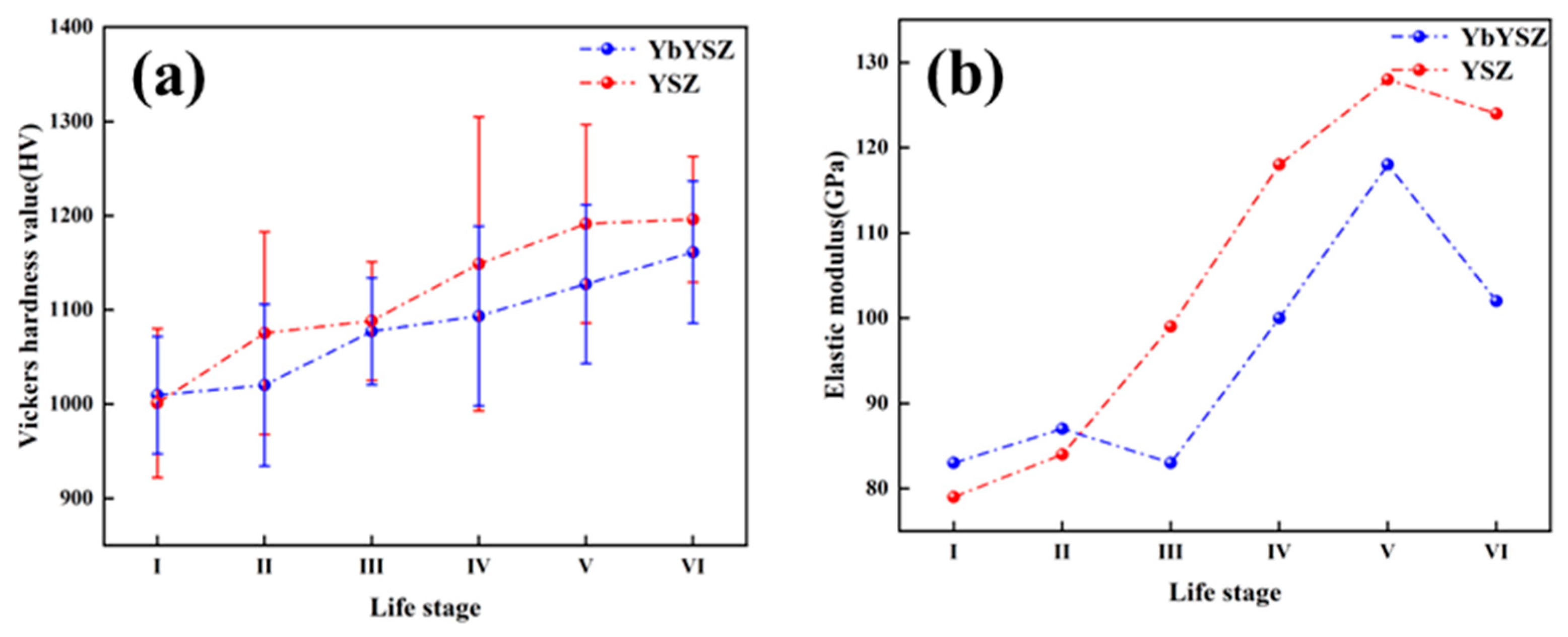
The hardness and elastic modulus of the coating are related to the composition and structure of the coating. In the early life stage, the hardness and elastic modulus of the YbYSZ coating are slightly higher than that of the YSZ coating due to the incorporation of Yb3+. With the evolution of the life stage, the hardness of the two coatings showed an increasing trend, and the elastic modulus showed a trend of increasing first and then decreasing, which was related to the sintering behavior of the coating and the accumulation of residual stress in the coating. The hardness and elastic modulus of the YSZ coating were higher than that of the YbYSZ coating, and the elastic modulus was larger, which would lead to premature failure of the coating. Therefore, YbYSZ exhibits good mechanical properties under coupling conditions.

Author Contributions

Conceptualization, W.L., Y.L. and T.Y.; Methodology, W.L., W.Z., C.L. and C.Z.; Formal analysis, W.L.; Investigation, W.L.; Data curation, W.L.; Writing—original draft, W.L.; Writing—review & editing, W.L.; Supervision, W.W. and S.T.; Project administration, W.W. and S.T.; Funding acquisition, W.W. and S.T. All authors have read and agreed to the published version of the manuscript.

Funding

This research was sponsored by the National Natural Science Foundation of China (52175136, 52130511), Science Center for Gas Turbine Project (P2021-A-IV-002-002), Shanghai Joint Innovation Program in the Field of Commercial Aviation Engines, National High Technology Research and Development Program of China (2021YFB3702202), and Key Research and Development Projects in Anhui Province (2022a05020004).

Data Availability Statement

No new data were created.

Conflicts of Interest

The authors declare no conflict of interest.

References

  1. Dong, H.; Liang, X.; Bai, J.; Lan, L.; Wang, X.; Zou, H.; Wang, Y.; Tian, W.; Mao, J.; Zhang, X. The relationship between the film hole distribution and thermal cycle performance of TBCs by APS and HVOF. Surf. Coat. Technol. 2023, 467, 129694. [Google Scholar] [CrossRef]
  2. Poursaeidi, E.; Jamalabad, Y.Y.; Rahimi, J.; Sigaroodi, M.R.J. The effect of CMAS penetration on the micro-structure and failure of the TBCs applied by APS/APS method. Surf. Coat. Technol. 2022, 451, 129053. [Google Scholar] [CrossRef]
  3. Li, C.; Guo, H.; Gao, L.; Wei, L.; Gong, S.; Xu, H. Microstructures of Yttria-Stabilized Zirconia Coatings by Plasma Spray-Physical Vapor Deposition. J. Therm. Spray Technol. 2015, 24, 534–541. [Google Scholar] [CrossRef]
  4. Nieto, A.; Agrawal, R.; Bravo, L.; Hofmeister-Mock, C.; Pepi, M.; Ghoshal, A. Calcia–magnesia–alumina–silicate (CMAS) attack mechanisms and roadmap towards Sandphobic thermal and environmental barrier coatings. Int. Mater. Rev. 2021, 66, 451–492. [Google Scholar] [CrossRef]
  5. Dong, T.-S.; Kong, L.-C.; Fu, B.-G.; Li, J.-K.; Li, G.-L. Effect of CeO2 doping on high temperature oxidation resistance of YSZ TBCs. Ceram. Int. 2022, 48, 36450–36459. [Google Scholar] [CrossRef]
  6. Krause, A.R.; Li, X.; Padture, N.P. Interaction between ceramic powder and molten calcia-magnesia-alumino-silicate (CMAS) glass, and its implication on CMAS-resistant thermal barrier coatings. Scr. Mater. 2016, 112, 118–122. [Google Scholar] [CrossRef]
  7. Fang, H.; Wang, W.; Zhang, C.; Wang, Y.; Yang, T.; Yang, Z.; Liu, Y.; Ye, D. Comparative study on failure behavior of promising CMAS-resistant plasma-sprayed thermal barrier coatings in burner rig test with/without CMAS deposition. Ceram. Int. 2023, 49, 12390–12407. [Google Scholar] [CrossRef]
  8. Li, H.; Yu, Y.; Fang, B.; Xiao, P.; Li, W.; Wang, S. Calcium-magnesium-alumina-silicate (CMAS) corrosion behavior of A6B2O17 (A = Zr, Hf; B = Nb, Ta) as potential candidate for thermal barrier coating (TBC). Corros. Sci. 2022, 204, 110395. [Google Scholar] [CrossRef]
  9. Bolcavage, A.; Feuerstein, A.; Foster, J.; Moore, P. Thermal Shock Testing of Thermal Barrier Coating/Bondcoat Systems. J. Mater. Eng. Perform. 2004, 13, 389–397. [Google Scholar] [CrossRef]
  10. Traeger, F.; Vaßen, R.; Rauwald, K.-H.; Stöver, D. Thermal Cycling Setup for Testing Thermal Barrier Coatings. Adv. Eng. Mater. 2003, 5, 429–432. [Google Scholar] [CrossRef]
  11. Kang, Y.; Bai, Y.; Bao, C.; Wang, Y.; Chen, H.; Gao, Y.; Li, B. Defects/CMAS corrosion resistance relationship in plasma sprayed YPSZ coating. J. Alloys Compd. 2017, 694, 1320–1330. [Google Scholar] [CrossRef]
  12. Kirbiyik, F.; Gok, M.G.; Goller, G. Application of thermal gradient and thermal cycling tests to Al2O3/CYSZ functionally graded TBC in the presence of simultaneous hot corrosion and CMAS effects. Surf. Coat. Technol. 2022, 444, 128688. [Google Scholar] [CrossRef]
  13. Kim, D.-J.; Shin, I.-H.; Koo, J.-M.; Seok, C.-S.; Lee, T.-W. Failure mechanisms of coin-type plasma-sprayed thermal barrier coatings with thermal fatigue. Surf. Coat. Technol. 2010, 205, S451–S458. [Google Scholar] [CrossRef]
  14. Guo, L.; Yan, Z.; Yu, Y.; Yang, J.; Li, M. CMAS resistance characteristics of LaPO4/YSZ thermal barrier coatings at 1250 °C–1350 °C. Corros. Sci. 2019, 154, 111–122. [Google Scholar] [CrossRef]
  15. Li, C.-J.; Li, Y.; Yang, G.-J.; Li, C.-X. Evolution of lamellar interface cracks during isothermal cyclic test of plasma-sprayed 8YSZ coating with a columnar-structured YSZ interlayer. J. Therm. Spray Technol. 2013, 22, 1374–1382. [Google Scholar] [CrossRef]
  16. Wei, Z.-Y.; Dong, X.-X.; Cai, H.-N.; Li, G.-R.; Zhao, S.-D. Vertical crack distribution effect on the TBC delamination induced by crack growth from the ceramic surface and near the interface. Ceram. Int. 2022, 48, 33028–33040. [Google Scholar] [CrossRef]
  17. Huang, J.; Wang, W.; Yu, J.; Wu, L.; Feng, Z. Effect of Particle Size on the Micro-cracking of Plasma-Sprayed YSZ Coatings During Thermal Cycle Testing. J. Therm. Spray Technol. 2017, 26, 755–763. [Google Scholar] [CrossRef]
  18. Bakan, E.; Mack, D.E.; Mauer, G.; Mücke, R.; Vaßen, R. Porosity–property relationships of plasma-sprayed Gd2Zr2O7/YSZ thermal barrier coatings. J. Am. Ceram. Soc. 2015, 98, 2647–2654. [Google Scholar] [CrossRef]
  19. Ren, X.; Zhao, M.; Feng, J.; Pan, W. Phase transformation behavior in air plasma sprayed yttria stabilized zirconia coating. J. Alloys Compd. 2018, 750, 189–196. [Google Scholar] [CrossRef]
  20. Feng, Y.; Dong, T.-S.; Fu, B.-G.; Li, G.-L.; Liu, Q.; Wang, R. Thermal shock resistance of double-layer thermal barrier coatings. J. Mater. Res. 2020, 35, 2808–2816. [Google Scholar] [CrossRef]
  21. An, G.-S.; Li, W.-S.; Wang, Z.-P.; Feng, L.; Cheng, B.; Zhou, L.; Li, Z.-Y.; Zhang, Y. High-temperature oxidation and TGO growth behaviors of laser-modified YAG/YSZ double-ceramic-layer TBC. Trans. Nonferr. Met. Soc. China 2023, 33, 1178–1192. [Google Scholar] [CrossRef]
  22. Huang, J.; Wang, W.; Li, Y.; Fang, H.; Ye, D.; Zhang, X.; Tu, S. Improve durability of plasma-splayed thermal barrier coatings by decreasing sintering-induced stiffening in ceramic coatings. J. Eur. Ceram. Soc. 2020, 40, 1433–1442. [Google Scholar] [CrossRef]
  23. Yang, G.-J.; Chen, Z.-L.; Li, C.-X.; Li, C.-J. Microstructural and mechanical property evolutions of plasma-sprayed YSZ coating during high-temperature exposure: Comparison study between 8YSZ and 20YSZ. J. Therm. Spray Technol. 2013, 22, 1294–1302. [Google Scholar] [CrossRef]
  24. Roncallo, G.; Barbareschi, E.; Cacciamani, G.; Vacchieri, E. Effect of cooling rate on phase transformation in 6–8 wt% YSZ APS TBCs. Surf. Coat. Technol. 2021, 412, 127071. [Google Scholar] [CrossRef]
  25. Drexler, J.M.; Chen, C.-H.; Gledhill, A.D.; Shinoda, K.; Sampath, S.; Padture, N.P. Plasma sprayed gadolinium zirconate thermal barrier coatings that are resistant to damage by molten Ca–Mg–Al–silicate glass. Surf. Coat. Technol. 2012, 206, 3911–3916. [Google Scholar] [CrossRef]
  26. Kirschner, M.; Wobst, T.; Rittmeister, B.; Mundt, C. Erosion Testing of Thermal Barrier Coatings in a High Enthalpy Wind Tunnel. In Turbo Expo: Power for Land, Sea, and Air; American Society of Mechanical Engineers: New York, NY, USA, 2014; p. V006T002A002. [Google Scholar]
  27. Guo, S.; Kagawa, Y. Effect of thermal exposure on hardness and Young’s modulus of EB-PVD yttria-partially-stabilized zirconia thermal barrier coatings. Ceram. Int. 2006, 32, 263–270. [Google Scholar] [CrossRef]
  28. Thompson, J.; Clyne, T. The effect of heat treatment on the stiffness of zirconia top coats in plasma-sprayed TBCs. Acta Mater. 2001, 49, 1565–1575. [Google Scholar] [CrossRef]
Figure 1. Morphologies of (a,b) YbYSZ, (d,e) YSZ and (c,f) particle size distribution of corresponding powders.
Coatings 13 01495 g001
Figure 2. Morphology of the as-sprayed (a) YbYSZ coating and (b) YSZ coating.
Coatings 13 01495 g002
Figure 3. Lifetime comparison of two kinds of coatings under the condition of thermal cycling–CMAS.
Coatings 13 01495 g003
Figure 4. Macroscopic and cross-sectional morphologies of the peeling area of the (ae) YbYSZ coating and the (fj) YSZ coating at different life stages.
Coatings 13 01495 g004aCoatings 13 01495 g004b
Figure 5. Morphologies of the YbYSZ coating (af) and the YSZ coating (gl) at different life stages.
Coatings 13 01495 g005aCoatings 13 01495 g005b
Figure 6. Effect of life stage on (a) the crack length and (b) the crack density of coatings.
Coatings 13 01495 g006
Figure 7. Relation between the life stage and the porosity of the coatings.
Coatings 13 01495 g007
Figure 8. XRD patterns of (a) YbSZ coatings and (b) YSZ coatings at different life stage before and after thermal cycling-CMAS test.
Coatings 13 01495 g008
Figure 9. (a) Hardness and (b) elastic modulus at different life stages.
Coatings 13 01495 g009
Table 1. Plasma spraying parameters for TBCs deposition.
ParameterBCYbYSZYSZ
Current, A600630600
Power, kW403940
Primary gas flow rate, Ar, L/min504040
Carrier gas flow rate, Ar, L/min99.59
Spray distance, mm120110100
Traverse speed of gun, mm/s900500500
Thickness, μm80330330
Disclaimer/Publisher’s Note: The statements, opinions and data contained in all publications are solely those of the individual author(s) and contributor(s) and not of MDPI and/or the editor(s). MDPI and/or the editor(s) disclaim responsibility for any injury to people or property resulting from any ideas, methods, instructions or products referred to in the content.

