Abstract
Based on the new high-modulus carbon fiber CCM40J-6k, which is the critical raw material of a solar panel, the molding process of a mesh face sheet combined with epoxy resin, the overall mechanical performance of a mesh face sheet combined with aluminum honeycomb, the compatibility with polyimide insulation film + solar cell circuit, and the space environment adaptability must pass a test verification and assessment as the premise for large-scale orbit applications. Therefore, based on the traditional carbon fiber M40JB-6k as a reference, a systematic verification project was conducted to apply the CCM40J-6k carbon fiber composite at the process, component, and assembly levels. Six aspects of testing and verifying items were conducted, including mechanical properties under room temperature and thermal shock conditions, bonding force of mesh nodes, comparison of the adaptability of domestic and imported carbon fiber substrates to high–low temperature alternation, the ability of domestic carbon fiber substrates to adapt to the thermal environment after laying solar cell circuits, and in-orbit lifespan of solar panels. Based on the verification results, the mechanical properties of the substrate are the same as those of the imported M40JB-6k, and the actual molding process for M40JB-6k can be utilized. Sample pieces of the substrates can withstand the thermal shock and thermal cycling tests. The bending stiffness of the sample pieces before and after the tests is 3.5%~9.6% higher, and the bending strength is 4.2%~7.2% lower. The tensile strength of mesh nodes made of domestic carbon fiber is 18.9% higher than that of mesh nodes made of imported carbon fiber. The CCM40J-6k substrate is similar to triple-junction GaAs solar cells. The change rates of the open-circuit voltage and the short-circuit current of solar panels based on domestic carbon fiber after fatigue thermal cycling with 2070 cycles are 0.55% and 0.24%, respectively. The above results indicate that the comprehensive performance of the domestic carbon fiber CCM40J-6k meets the requirements and can be applied to solar panels for solar arrays.
1. Introduction
A space solar array serves as the power supply for a spacecraft and the substrate serves as a mounting base for solar cells (Figure 1). A solar panel is a combination of a substrate and a solar cell circuit, and its specific composition is shown in Figure 2. With polyimide film as the boundary, the lower part is the substrate and the upper part is the solar cell circuit. A polyimide film pasted on the surface of the substrate is used to meet the insulation requirements between the solar cell and the substrate [1,2,3].
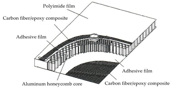
Figure 1.
Schematic diagram of the composition of the substrate for a solar array.
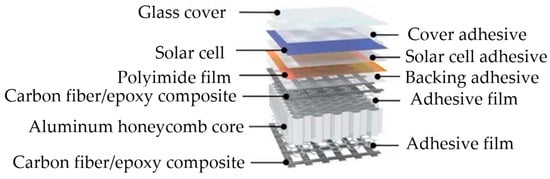
Figure 2.
Schematic diagram of the composition of a solar panel for a solar array.
“The upper and lower mesh face sheets of carbon fiber composite + an aluminum honeycomb core + polyimide film” is the typical structure of a substrate. As the installation foundation of a solar cell circuit, the substrate needs to provide support and an excellent mechanical environment for the solar cell circuit. The substrate is required to have the characteristics of lightweight, high stiffness, high strength, and high dimensional stability. These characteristics mainly depend on the high-modulus carbon fiber that constitutes the main structure of the substrate [4,5,6,7,8,9]. In recent years, high-modulus carbon fiber and other raw material imports have become increasingly limited, and the cost has risen. In addition, controllability of critical raw materials is the precondition for top-quality development of aerospace technology. Therefore, it is increasingly urgent to study the application of domestic high-modulus carbon fibers to solar panels [10,11,12,13].
As the critical raw material for solar panels, the novel high-modulus carbon fiber CCM40J-6k has never been applied to Chinese solar panels in orbit. The solar substrate’s mechanical properties and special thermal-cycle tolerance based on a domestic high-modulus carbon fiber (i.e., CCM40J-6k) are crucial factors for determining whether it can be applied to solar panels on a large scale [14,15,16]. Solar panels must withstand mechanical loads during launch and orbit. In addition, the temperature of the environment changes alternately due to the interaction between a cold black environment (the Earth’s shadow area) and a thermal vacuum (the Earth’s sunny side) that a spacecraft experiences during orbital operation. Figure 2 shows that a solar panel is composed of various non-metallic materials that are connected by adhesive bonding. The thermal deformation coefficients of each material are different, and the material’s thermal conductivity is significantly reduced compared to the metal structure. Thermal stress caused by temperature fluctuations in orbit and thermal deformation caused by temperature gradients are significant, which, to some extent, affect the integrity of a panel’s structure, leading to detachment or damage of the solar cells. Thus, the issues of matching mesh face sheets, aluminum honeycomb cores, and polyimide film; matching the substrate and solar cell circuit in alternating thermal environments; and long lifespan must be solved.
In [17], the authors studied the surface characteristics and crystal structures of three domestic (CCM40J, CCM40, and CCM46J) and one imported (M40JB) high-modulus carbon fibers, and the micro interface and multifilament mechanical properties of high-modulus carbon fibers and epoxy resin. However, in [17], they did not elaborate on suitable applications of these domestic carbon fiber/epoxy resin composites. A study by [18] analyzed the adhesive content of the adhesive absorption system for two composite materials, i.e., imported HM40-3K/TDE-86 and domestic BSCHM40-3K/TDE-86, used in the curing and adhesive absorption process of a solar substrate. However, it was also pointed out that different fiber and resin combinations require adjusting the adhesive absorption system according to the actual situation. The better the wettability of the fiber and resin, the greater the binding force between them.
In this study, we take imported carbon fiber M40JB-6k as the comparative object and analyze the critical links of applying the domestic carbon fiber CCM40J-6k on a mesh substrate for solar arrays, as well as the corresponding process verification and environmental adaptability verification projects. Additionally, matching validation of the substrate with the solar cell circuit based on the domestic CCM40J-6k carbon fiber materials, and the environmental adaptability validation of the solar panels are carried out. The verification results of the test samples are provided, and based on this, a complete application verification project for carbon fiber composite materials at the process level, component level, and assembly level is presented for the first time, providing technical references for the actual application of the product.
2. Comparison of Surface Physical Properties, Crystal Structure, and Performance of Two Types of Carbon Fibers
M40JB-6k is produced by the Toray Company of Japan and CCM40J-6k is produced by the Weihai Tuozhan Fiber Company of China. Figure 3a–h show scanning electron microscope (SEM) photos of the surfaces of the high-modulus carbon fibers M40JB and CCM40J, respectively. It can be seen that there are grooves on the surface of both types of high-modulus carbon fibers, indicating that the spinning process of their precursor fibers should be the same, that is, both wet spinning and groove morphology is the same. The surface grooves of M40JB and CCM40J are both shallow and dense. Figure 4 shows SEM photos of cross sections of high-modulus carbon fibers. The cross-sectional shapes of the two high-modulus carbon fibers are approximately circular, elliptical, and cashew-shaped with prominent surface grooves.
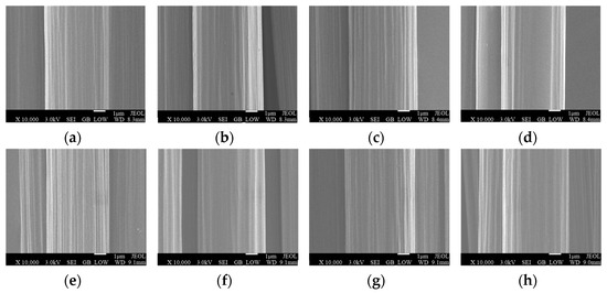
Figure 3.
SEM photographs of high-modulus carbon fiber surfaces: (a–d) M40JB-6k; (e–h) CCM40J-6k (In the above picture, “X” letter stands for the magnitude of enlargement, “3.0 kV” stands for the accelerating voltage, “WD” stands for the working distance).
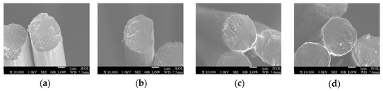
Figure 4.
SEM photographs of carbon fiber cross sections: (a,b) M40JB-6k; (c,d) CCM40J-6k (in the above picture, “X” letter stands for the magnitude of enlargement, “3.0 kV” stands for the accelerating voltage, “WD” stands for the working distance).
The crystal structure parameters of two types of high-modulus carbon fibers are shown in Table 1. It can be seen that the orientation angles (θ) of the two high-modulus carbon fibers (i.e., M40JB and CCM40J) are 25.8° and 25.919°, respectively, and the spaces between layers are 0.3435 nm and 0.3450 nm, respectively, which is greater than that of ideal graphite (d is 0.3354 nm), indicating that its graphite structure is not yet perfect. Accordingly, for M40JB and CCM40J, the crystallites Lc slightly decrease.

Table 1.
Crystal structure parameters of two types of high-modulus carbon fibers.
Through a performance comparison between CCM40J-6k and M40JB-6k (Table 2), the tensile modulus of the CCM40J-6k carbon fiber is 3% higher than that of the M40JB-6k carbon fiber, the tensile strength is 14% higher, the elongation is better than that of the M40JB-6k carbon fiber, and the volume density of the CCM40J-6k carbon fiber is the same as that of the M40JB-6k carbon fiber.
Table 2.
Performance comparison of the two types of carbon fibers.
3. Key Design and Verification Matrix
From the application experience of M40JB-6k carbon fiber, the critical links in the design of a high-modulus carbon-fiber substrate and its special environmental adaptability after matching with a solar cell circuit include the mechanical properties (stiffness and strength) under different temperatures, the micro tensile and peeling properties of mesh nodes, the appearance, the conductivity, the insulation properties, and the electrical properties of the solar panel after temperature cycling, and the solar panel’s thermal environment test simulating in-orbit life [19,20,21,22].
In order to further prove the feasibility of applying the CCM40J-6k carbon fiber to a solar panel, according to the critical links of the design described, Figure 5 shows the validation matrix. The first requirement was to determine the performance of the test pieces based on the carbon fiber/epoxy composites at room temperature, the mechanical properties after thermal shock, the performance of the mesh nodes, and the thermal cycling properties of the substrate. After laying the solar cell circuit, the domestic solar panel was tested, including its ability to adapt to the thermal environment, and the in-orbit lifespan of the solar panel was verified. As previously mentioned, the molding process parameters of a substrate based on the CCM40J-6k/epoxy composite, and the matching parameters for the solar panel were acquired, so that it could accommodate the high overload of the satellite when launching and the alternating effect of high and low temperature on orbit (−170 °C~120 °C) [23,24].
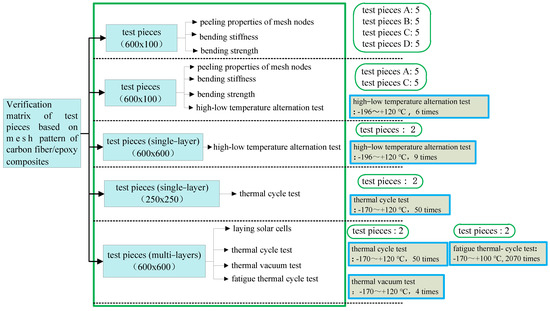
Figure 5.
Verification matrix of test pieces based on the mesh pattern of carbon fiber/epoxy composites (all the test pieces are in the green border).
4. Performance of Test Pieces Based on the CCM40J-6k Carbon Fiber/Epoxy Composite at Room Temperature
The main purpose of this test was to determine whether the mechanical properties of the substrate based on the CCM40J-6k carbon fiber/epoxy composite met the requirements, and to assure that the structure and the molding process of the test pieces were consistent with the real product [15].
Preparation of the CCM40J-6k/epoxy resin composite materials adopted a winding and stacking molding process, which involved impregnating continuous high-modulus carbon fiber bundles with epoxy resin adhesive solution and continuously winding them on the core mold under the conditions of controlling winding tension, winding speed, and predetermined line shape, and then cutting and stacking them. Finally, the mesh face sheets made of the CCM40J-6k/epoxy resin composite were cured under heating conditions.
The test piece was a sandwich structure. The upper and lower layers of the substrate were both single-layer orthogonal mesh face sheets based on the CCM40J-6k carbon fiber/epoxy resin, and the middle part was an aluminum honeycomb core with a height of 24 mm, as shown in Figure 6.
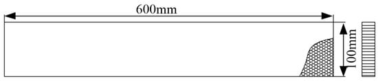
Figure 6.
Specifications of the solar array substrate.
The three-point extension method was used to measure the bending stiffness of the substrate. The bending strength of the substrate was measured by using four-point loading in accordance with the relevant provisions of the Chinese national standard (GJB 130.9A-2021). The results are shown in Table 3.
Table 3.
Results of test pieces based on carbon fiber/epoxy composites at room temperature.
Based on the above results, two types of substrate test pieces of the CCM40J-6k and M40JB-6k carbon fiber/epoxy composites were made with a size of 600 mm × 55 mm. The upper and lower layers of the substrate were both single-layer orthogonal mesh face sheets with a spacing of 6 mm × 4 mm, and the interlayer was an aluminum honeycomb core with a height of 24 mm. The bending stiffness and bending strength of the substrate test pieces were measured using the same method, and the results are shown in Table 4.
Table 4.
Comparison of mechanical performance between two types of substrates.
- (1)
- For test pieces with a mesh spacing of 6 mm × 4 mm, the bending stiffness of the aluminum honeycomb along the long side in the L direction is 2.4% higher, the shear stiffness is 52% higher, the failure load is 7.6% higher, and the bending strength is 7.5% higher than that of the aluminum honeycomb along the long side in the W direction.
- (2)
- For test pieces with a mesh spacing of 5.3 mm × 3.8 mm, the bending stiffness of the aluminum honeycomb along the long side in the L direction is 8.1% higher, the shear stiffness is 71% higher, the failure load is 0.4% higher, and the bending strength is 0.5% higher than that of the aluminum honeycomb along the long side in the W direction.
- (3)
- At the same mesh spacing, the shear stiffness of the test piece is significantly improved along the long side of the test piece in the L direction of the aluminum honeycomb, while the bending stiffness, failure load, and bending strength are slightly increased.
- (4)
- For the L direction of the aluminum honeycomb along the long side, and a mesh spacing of 5.3 mm × 3.8 mm compared with a mesh spacing of 6 mm × 4 mm, the bending stiffness of the test piece is 10.3% higher, the shear stiffness is 7.4% higher, the failure load is 5% higher, and the bending strength is 5% higher.
- (5)
- For the W direction of the aluminum honeycomb along the long side, and a mesh spacing of 5.3 mm × 3.8 mm compared with a mesh spacing of 6 mm × 4 mm, the bending stiffness, shear stiffness, failure load, and bending strength of the test piece are 4.5%, 4.7%, 12.5, and 12.2% higher, respectively.
- (6)
- The mechanical properties of the substrates based on the CCM40J-6k and M40JB-6k carbon fiber/epoxy composites are very similar. For a mesh spacing of 6 mm × 4 mm, the bending stiffness of the CCM40J-6k carbon-fiber substrate is 9.8 ‰ lower than that of the M40JB-6k carbon-fiber substrate, and the bending strength is 2.9% higher. Considering the average error of molding process parameters, this difference can be ignored.
- (7)
- In conclusion, when the aluminum honeycomb is in the same direction, the denser the mesh spacing is, the greater the bending stiffness, strength, shear stiffness, and failure load will be, and the corresponding weight will also be increased. This trend is consistent with the application of imported M40JB-6k carbon fiber, indicating that the performance of test pieces based on the domestic CCM40J-6k carbon fiber/epoxy composite at room temperature meets the requirements. In addition, when designing the mesh spacing of carbon fiber, it is still necessary to comprehensively consider the optimal solution between the mechanical properties and weight of the substrate.
5. Performance of Test Pieces Based on the CCM40J-6k Carbon Fiber/Epoxy Composite before and after High–Low Temperature Alternation
Based upon the test conducted at room temperature, this test simulated the temperature-alternating environment of solar arrays in orbit. Temperature gradient and resistance to temperature alternation of carbon fiber/epoxy resin substrate structures were evaluated to ensure structural integrity and primary performance after experiencing harsh space environments [25,26,27,28,29,30,31].
Five samples of test piece A and five samples of test piece C were selected for immersion in a liquid nitrogen tank (~−196 °C) for 15 min, and then kept at room temperature for 10 min. When the temperature in the incubator reached +120 (±5) °C, the samples were kept at that temperature for 120 min, and then kept at room temperature for 60 min (the next cycle test was conducted after room temperature was restored). A total of 6 cycles were performed.
After the high–low temperature alternation, the bending stiffness, strength, shear stiffness, and other mechanical properties were tested according to the Chinese national standard (GJB 130.9A-2021). Table 5 shows the test results.
Table 5.
Results of test pieces based on carbon fiber/epoxy composites at room temperature and after high–low temperature alternation.
The test results, shown in Table 5, are as follows:
- (1)
- For test piece A, after high–low temperature alternation, the bending stiffness is 3.5% higher, the shear stiffness is 11% higher, the failure load is 7.1% lower, and the bending strength is 7.2% lower than that under room temperature.
- (2)
- For test piece C, after high–low temperature alternation, the bending stiffness is 9.6% higher, the shear stiffness is 1.6% lower, the failure load is 4.0% lower, and the bending strength is 4.2% lower than that under room temperature.
- (3)
- After high–low temperature alternation, the test pieces’ bending, shear, and destructive properties increase or decrease slightly. In general, the mechanical properties of the test piece based on the CCM40J-6k carbon fiber/epoxy composite are not significantly reduced compared with those before the high–low temperature alternation. After a certain number of thermal cycles, the thermal stress can be released effectively through the deformation of the resin or interface, and the mechanical properties gradually become stable. It is proven that domestic carbon fiber has high performance in combination with epoxy resin and can withstand high–low temperature alternations in space.
6. Performance of the Mesh Nodes of the Mesh Face Sheet
The bonding firmness of mesh nodes is determined by the micro-tensile and debonding properties of the material, which are essential for ensuring mesh face sheets’ structural integrity and flatness.
In order to test the tensile and debonding properties of the mesh nodes of domestic mesh face sheets, it is necessary to test the tensile strength of the mesh cross joints. A schematic diagram of a mesh node is shown in Figure 7. The tensile strength of the mesh node (Mpa) = , where p is the failure force of mesh node (N), a is the node length (mm), and b is the node width (mm).
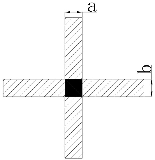
Figure 7.
Schematic diagram of a mesh cross node.
The tensile properties of the mesh nodes of the domestic mesh face sheet (CCM40J-6k) and imported mesh face sheet (M40JB-6k) were tested.
The test results, shown in Table 6, include the following:
- (1)
- For the domestic carbon fiber CCM40J-6k, the epoxy resin content is 31% compared with 34%, the average failure force of the mesh nodes is 44.8% higher, and the average tensile strength of the mesh nodes is 6.1% higher. Therefore, the smaller the epoxy resin content, the greater the tensile strength of the mesh nodes. However, the content of epoxy resin is also related to the surface state of the carbon fiber. The epoxy resin content should be controlled as much as possible under the condition that carbon fiber can be completely immersed.
- (2)
- Under the same epoxy resin content, the average failure force of the mesh nodes of the domestic mesh face sheet is 31.3% lower and the average tensile strength is 18.9% higher.
Table 6.
Results of tensile performance for mesh nodes.
Table 6.
Results of tensile performance for mesh nodes.
| Carbon Fiber | Number of Samples | Epoxy Resin Content | Average Value | |||
|---|---|---|---|---|---|---|
| a/mm | b/mm | p/N | Tensile Strength of Mesh Node/MPa | |||
| CCM40J-6k | 10 | 31% | 2.238 | 2.268 | 18.4 | 3.60 |
| 10 | 34% | 1.941 | 1.942 | 12.7 | 3.39 | |
| M40JB-6k | 10 | 34% | 2.828 | 2.298 | 18.5 | 2.85 |
7. Verification of the Thermal Cycle Tests of Substrates Based on Domestic and Imported Carbon Fiber/Epoxy Composites
Firstly, a thermal cycle test of the carbon fiber/epoxy resin substrates was conducted to verify whether the structural integrity after the thermal cycle could be guaranteed after the substrate was molded [32].
Two test pieces based on the domestic carbon fiber CCM40J-6k and the imported M40JB-6k were prepared (the upper and lower mesh face sheets of the test piece were both single layer, the mesh spacing was 4 mm × 6 mm, and polyimide film was pasted on one side). The thickness of the substrate was 25.4 mm. The changes in the two types of substrates after the thermal cycle test were compared. The test equipment adopted a CH500C temperature and humidity box, with a temperature range of −180~+180 °C and a working space of 0.3 m3.
Two test pieces were selected for testing, as shown in Figure 8:
- Temperature: For high temperature, the temperature was kept at +120 (±5) °C; for low temperature, the average temperature was lower than −170 °C;
- Cooling rate: The maximum capacity of the equipment was used for cooling from high-temperature working conditions to low-temperature working conditions;
- Heating rate: The heating time was about 45 min, from −165 °C to 80 °C, and the maximum heating rate was not less than 40 °C/min;
- Number of cycles: 50 cycles in total, starting from the high-temperature working conditions.

Figure 8.
Thermal-cycle curves of substrate testing based on two types of carbon fibers.
Figure 8.
Thermal-cycle curves of substrate testing based on two types of carbon fibers.

After the test, the surface integrity of the test pieces was checked. Then, nondestructive detection of the test pieces using an infrared thermal imager was conducted, as shown in Figure 9. The conclusions are as follows:
- (1)
- The two test pieces were in good bonding condition at the carbon-fiber orthogonal joints on both sides, without debonding joints. The bonding condition between carbon fiber and the aluminum honeycomb core, and the bonding condition between polyimide film and carbon fiber were both stable, without debonding problems.
- (2)
- The nondestructive detection of the two test pieces using an infrared thermal imager showed that the bonding at the mesh nodes and between the carbon fiber and aluminum honeycomb core was in good condition, which indicated that the domestic carbon-fiber substrate (CCM40J-6k) could adapt to temperature alternation, and further proved the feasibility of the application of domestic carbon fiber in large-size structural part.

Figure 9.
Nondestructive testing by infrared thermal imaging of substrate test based on two types of carbon fibers: (a) CCM40J-6k; (b) M40JB-6k.
Figure 9.
Nondestructive testing by infrared thermal imaging of substrate test based on two types of carbon fibers: (a) CCM40J-6k; (b) M40JB-6k.

8. Verification of the Thermal Environment Test of a Solar Panel Based on the CCM40J-6k Carbon Fiber/Epoxy Composite
8.1. Test Piece of Substrate
Based on the verification of the above tests, a multi-layer substrate structure using the CCM40J-6k carbon fiber/epoxy composite was made imitating the actual structure of the solar array, as shown in Figure 10. The manufacturing process was consistent with that of the imported M40JB-6k carbon fiber.
- (1)
- Area 1 is the single layer with a mesh spacing of 4 mm × 6 mm (top layer);
- (2)
- Area 2 has two layers (top layer + second layer with a mesh spacing of 6 mm × 4 mm);
- (3)
- Area 3 has three layers (top layer + second layer with a mesh spacing of 6 mm × 4 mm + third layer with a mesh spacing of 4 mm × 6 mm);
- (4)
- Area 4 has four layers (top layer + second layer with a mesh spacing of 6 mm × 4 mm + third layer with a mesh spacing of 4 mm × 6 mm + fourth layer with a mesh spacing of 6 mm × 4 mm);
- (5)
- Area 5 has three layers (top layer + second layer with a mesh spacing of 6 mm × 4 mm + third layer with a mesh spacing of 4 mm × 6 mm);
- (6)
- Area 6 has three layers (top layer + second layer with a mesh spacing of 6 mm × 4 mm + third layer with a mesh spacing of 4 mm × 6 mm).

Figure 10.
Schematic diagram of a multi-layer substrate (the unit of all numbers in the figure is mm).
Figure 10.
Schematic diagram of a multi-layer substrate (the unit of all numbers in the figure is mm).

8.2. Test Piece of Solar Panel
Triple-junction GaAs solar cells were pasted on the substrate in series and parallel to form a solar cell circuit. The solar panel size was 600 mm × 600 mm × 25.4 mm. The real solar cells were pasted at a specified position (the size of a single solar cell is 39.8 mm × 60.4 mm), totaling 18 pieces, and other areas were covered with analog solar cells, as shown in Figure 11.
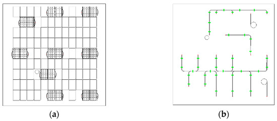
Figure 11.
Schematic diagram of the solar panel for the thermal-cycle test: (a) The obverse side; (b) the reverse side (the green points mean silicon rubber for fixation; the small circles mean cables).
8.3. Atmospheric Thermal Cycle Test
A test piece of the solar panel was selected for the atmospheric thermal cycle test. The test conditions were the same as those in Section 7, the temperature range was from −170 °C to +120 °C, and the number of cycles was 50 cycles.
8.4. Thermal Vacuum Test
The above solar panel was selected to continue the thermal vacuum test, as shown in Figure 12. In order to cover the satellite’s temperature in orbit, test pieces conduct thermal vacuum tests within a wide temperature range, so there is a high requirement for thermal vacuum equipment’s temperature control ability. This experiment used KM3 simulation chambers with a diameter of 4.2 m and a length of 6 m. The enclosed space formed by the heat sink had a diameter of 3.6 m and a length of 5 m. The vacuum degree in the vacuum chamber was better than 1.3 × 10⁻³ Pa. The test conditions included the following:
- (1)
- Pressure, ≤1.3 × 10⁻³ Pa;
- (2)
- Temperature range, −170~+120 °C;
- (3)
- Changing rate of temperature, according to the predictive value of changing rate when entering and exiting the shadow, which should not be lower than 10 °C/min;
- (4)
- Number of cycles, 4 cycles.

Figure 12.
Thermal vacuum test of the solar panel: (a) The obverse side; (b) the reverse side.
Figure 12.
Thermal vacuum test of the solar panel: (a) The obverse side; (b) the reverse side.

8.5. Test Results
- (1)
- Before and after the test, the circuit interconnection and bus ribbon of the test piece were inspected. The appearance of the circuit interconnection and bus ribbon was unchanged. After the test, the cracks in the solar cell and the glass cover were inspected, and no new cracks were found. The solder joints were free of desoldering, the wires were free of damage, and the adhesive layer was intact without desoldering.
- (2)
- Before and after the test, the conduction and insulation of the solar cell circuit of the test piece were checked, and the results were normal.
- (3)
- Before and after the test, the surface of carbon fiber was inspected, and no debonding was found on the cross node of the mesh face sheet on the back of the test piece and the front of the substrate with polyimide film.
- (4)
- The solar panel based on the domestic carbon fiber/epoxy composite successfully passed the thermal environment assessment, indicating that it has the ability to withstand temperature alternation in space.
9. Verification of Fatigue Thermal-Cycle Test of Solar Panel Based on the CCM40J-6k Carbon Fiber/Epoxy Composite
To further verify whether the electrical performance of the solar panel based on the CCM40J-6k carbon fiber/epoxy composite met the requirements within the on-orbit life of the high-orbit satellite (15 years), the temperature alternation of the solar array in space was simulated through a ground test, to verify whether the solar panel with triple-junction GaAs solar cells based on a domestic carbon-fiber substrate could withstand temperature alternation.
9.1. Test Piece of Solar Panel
The substrate fabrication based on the CCM40J-6k carbon fiber/epoxy composite was the same as in Section 8.1. On this basis, a test piece of solar panel with a size of 200 mm × 200 mm × 25.4 mm for a fatigue thermal-cycle test was fabricated, and 20 pieces of solar cells were pasted on; the size of one single solar cell was 30.6 mm × 40.3 mm. Three groups of current distribution modules and three fixing posts of cable were bonded on the back of the substrate, one isolating diode was installed on each current distribution module, and wires were led out separately, as shown in Figure 13.
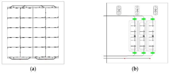
Figure 13.
Schematic diagram of the solar panel for the fatigue thermal-cycle test: (a) The obverse side; (b) the reverse side (the green ellipses mean silicon rubber for fixation; the red dots mean cables crossing from the obverse side to the reverse side).
9.2. Test Conditions
- (1)
- Ambient air pressure, normal pressure;
- (2)
- Temperature range, −170~+ 100 °C;
- (3)
- Changing rate of temperature, according to the predictive value of changing rate when entering and exiting the shadow, which should not be lower than 10 °C/min;
- (4)
- Number of cycles, 2070 cycles.
9.3. Test Process
High–low temperature alternation cycle tests with 2070 cycles were conducted on the test piece. It can be seen that the average rate of temperature change was greater than 20 °C/min, as shown in Figure 14. Before and after the test, the appearance, conductivity, insulation, and electrical properties of the test piece were checked. Electrical properties include conductivity and I–V curve tests; the former is measured by a multimeter, while the latter is tested using a solar simulator to simulate sunlight under 1 AM0 conditions.
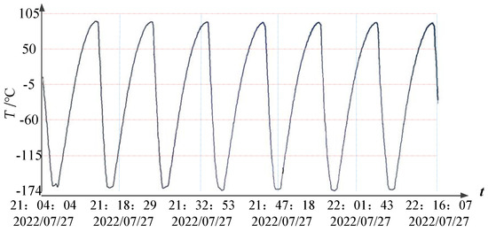
Figure 14.
The fatigue thermal-cycle curve of the solar panel based on triple-junction GaAs solar cells (the red dotted line represents the horizontal coordinate value, while the blue dotted line represents the vertical coordinate value).
9.4. Test Results
The solar cell and its surface state of the test piece were examined, and an I–V curve test was conducted before and after the test (Table 7 and Figure 15). The conclusions are as follows:
- (1)
- Before and after the test, the appearances of the solar cell, diode, interconnection, bus ribbon, conductor, solder joint, current distribution module, and fixing pile of cable were intact without debonding.
- (2)
- Before and after the test, the appearance of the solar cell and its glass cover was intact, and the insulation resistance value between the solar cell circuit and the substrate was above 100 MΩ.
- (3)
- The changing rates of the open-circuit voltage Voc and the short-circuit current Isc before and after the test were 0.55% and 0.24%, respectively, with very little change.
- (4)
- Before and after the test, the surface of the substrate was inspected, and no debonding was found on the cross node of the mesh face sheet on the back of the test piece and the front of the substrate with polyimide film.
- (5)
- The solar panel made from a domestic carbon fiber/epoxy composite successfully passed the fatigue thermal-cycle test, indicating that it could withstand temperature changes over the satellite’s lifetime, and the substrate and the solar cell were well matched.
Table 7.
Test results of the solar panel’s electrical performance before and after the fatigue thermal-cycle test.
Table 7.
Test results of the solar panel’s electrical performance before and after the fatigue thermal-cycle test.
| Item | Test Result | ||
|---|---|---|---|
| Before Test | After Test | Changing Rate | |
| Open-circuit voltage (Voc)/V | 26.873 | 26.888 | 0.55% |
| Short-circuit current (Isc)/A | 0.423 | 0.424 | 0.24% |
| Optimum operating voltage (Vmp)/V | 23.670 | 23.702 | 0.14% |
| Optimum operating current (Imp)/A | 0.397 | 0.398 | 0.25% |
| Maximum power (Pmax)/W | 9.409 | 9.437 | 0.30% |
| Fill factor (FF) | 0.826 | 0.827 | 0.01% |
| Open-circuit voltage (Voc)/V | 26.873 | 26.888 | 0.55% |
| Short-circuit current (Isc)/A | 0.423 | 0.424 | 0.24% |
| Optimum operating voltage (Vmp)/V | 23.670 | 23.702 | 0.14% |

Figure 15.
I-V curve of the solar panel for the fatigue thermal-cycle test, before and after the test.
Figure 15.
I-V curve of the solar panel for the fatigue thermal-cycle test, before and after the test.

10. Conclusions
- (1)
- As compared with M40JB-6k, the surface physical properties, crystal structure, and mechanical properties of CCM40J-6k are basically the same. The production process of the substrate for a solar panel based on CCM40J-6k can adopt that of M40JB-6k carbon fiber.
- (2)
- At the same mesh spacing, the shear stiffness of the CCM40J-6k test piece can be significantly improved along the long side of the test piece in the L direction of the aluminum honeycomb, while the bending stiffness, failure load, and bending strength increase slightly. Therefore, when designing the direction of the aluminum honeycomb and the mesh face sheet, the optimal solution of the mechanical properties of the substrate should be comprehensively considered.
- (3)
- Under the same epoxy resin content, the tensile strength of the CCM40J-6k mesh nodes is 18.9% higher than that of the imported carbon-fiber mesh nodes. A smaller amount of epoxy resin can significantly reduce product weight while ensuring carbon fibers can be completely immersed.
- (4)
- After the CCM40J-6k test piece undergoes thermal shock, the deformation of the resin or interface can effectively relieve thermal stress, resulting in stabilizing mechanical properties. Compared to the results before the experiment, the mechanical properties are slightly decreased, and the impact is acceptable. Through comparative thermal cycling tests of substrates based on two types of carbon fibers, it has been proven that the comprehensive performance of CCM40J-6k is equivalent to that of the imported M40JB-6k.
- (5)
- The CCM40J-6k solar panel passed the thermal vacuum and fatigue thermal cycling tests with 2070 cycles. The change rates of the open-circuit voltage and the short-circuit current of triple-junction gallium arsenide solar cells after the fatigue thermal cycling test are 0.55% and 0.24%, respectively. The appearance of the solar cell and glass cover is intact, and the insulation performance of the solar cell circuit is stable. This proves that the CCM40J-6k substrate and triple-junction gallium arsenide solar cells have high compatibility. A solar panel based on the domestic carbon fiber CCM40J-6k can withstand temperature shocks during the total on-orbit life of the satellite.
- (6)
- Based on the research results of this study, future space application verification of the domestic carbon fiber CCM40J-6k on full-size solar panels and solar arrays will be carried out.
Author Contributions
Conceptualization, S.Y. and L.S.; methodology, J.M.; software, S.R.; validation, S.Y. and J.M.; formal analysis, S.R.; investigation, S.R.; resources, J.M.; data curation, S.Y.; writing—original draft preparation, S.Y.; writing—review and editing, L.S.; visualization, S.Y.; supervision, L.S.; project administration, S.Y. and J.M.; funding acquisition, Y.C. All authors have read and agreed to the published version of the manuscript.
Funding
This research was funded by the Doctoral Innovation Fund of Xi’an University of Technology, grant number 252072104.
Institutional Review Board Statement
Not applicable.
Informed Consent Statement
Not applicable.
Data Availability Statement
The data are contained within the article.
Acknowledgments
We are grateful to the Beijing Spacecrafts Limited Company for providing us with the test pieces of substrates and to the Tianjin Institute of Power Sources for providing us with the solar cells.
Conflicts of Interest
The authors declare no conflict of interest.
References
- Tang, E.L.; Li, Z.; Zhang, Q.M.; Wang, M.; Xiang, S.H.; Liu, S.H.; He, L.P.; Han, Y.F.; Xia, J.; Wang, H.L.; et al. Discharges of plasma induced by hypervelocity impact on the solar array with different substrate structures. Int. J. Appl. Electrom. 2016, 51, 337–347. [Google Scholar]
- Yoon, M.S.; Shim, Y.B.; Han, Y.G. Influence of the thickness and doping concentration in p- and n-type poly-Si layers on the efficiency of a solar cell based on a carbon fiber. J. Opt. Soc. Korea 2015, 19, 199–205. [Google Scholar] [CrossRef]
- Yu, G.; Yang, D.Z.; He, S.Y.; Liu, Y.; Jiang, S.L.; Li, Z.J. A study on damage effect of vacuum thermocycling on M40J-epoxy composites. J. Reinf. Plast. Comp. 2005, 24, 1705–1711. [Google Scholar] [CrossRef]
- Wang, Q.Q.; Wang, P.P.; Qian, X.; Zhang, Y.G.; Yang, W. Effect of water-soluble thermoplastic polyimide sizing agent on interfacial properties of domestic high strength and high modulus carbon fiber reinforced composites br. J. Mater. Sci. 2023, 51, 174–182. [Google Scholar]
- Bowman, S.; Hu, X.Y.; Jiang, Q.R.; Qiu, Y.P.; Liu, W.S.; Wei, Y. Effects of Graphene-Oxide-Modified coating on the properties of Carbon-Fiber-Reinforced polypropylene composites. Coatings 2018, 8, 149. [Google Scholar] [CrossRef]
- Dong, X.W.; Li, A.; Yan, Y.Y.; Wang, P. Enhanced mechanical and damping properties of carbon fiber/epoxy composites by introducing the microcapsule particles. Polym. Compos. 2023, 43, 4609–4625. [Google Scholar] [CrossRef]
- Tonga, D.A.; Akbar, M.F.; Shrifan, N.; Jawad, G.N.; Ghazali, N.A.; Mohamed, M.; Al-Gburi, A.; Ab Wahab, M.N. Nondestructive evaluation of Fiber-Reinforced polymer using microwave techniques: A review. Coatings 2023, 13, 590. [Google Scholar] [CrossRef]
- Samson, P.E.; Kumaran, S.S.; Shanmugam, V.; Das, O. The effect of fiber orientation and stacking sequence on carbon/Kevlar/epoxy intraply hybrid composites under dynamic loading conditions. Polym. Advan. Technol. 2023, 34, 1585–1598. [Google Scholar] [CrossRef]
- Ma, Y.Y.; Wang, J.T.; Lu, K.; Xiang, Y.; Liu, Y.Q. The evolution of carbon fiber elements and their effects on fiber mechanical properties from molecular dynamics. Comp. Mater. Sci. 2023, 220, 112029. [Google Scholar] [CrossRef]
- Cariou, R.; Boulanger, B.; Voarino, P.; Roujol, Y.; Couderc, R.; Boirard, H.; Rapp, E.; Bourcier, F. Characterization of solar array’s cells to substrate bonding interface. In Proceedings of the European Space Power Conference (ESPC), Juan-les-Pins, France, 30 September–4 October 2019. [Google Scholar]
- Li, W.W.; Kang, H.L.; Xu, J.; Liu, R.G. Microstructures of high-strength high-modulus carbon fibers and high-modulus carbon fibers. Acta Polym. Sin. 2018, 49, 380–388. [Google Scholar]
- Wang, Y.F.; Liu, G.; Peng, G.Q.; Li, S.L.; Xie, F.Y. Interfacial properties of domestic T700 carbon fiber/bismaleimide composites. J. Mater. Sci. 2018, 46, 140–145. [Google Scholar]
- Qi, G.C.; Liu, J.X.; Yu, Y.L.; Zhang, B.M.; Du, S.Y. Assessment of interfacial adhesion between carbon fiber and epoxy by transverse fiber bundle and single fiber fragmentation tests. In Proceedings of the 20th International Conference on Composite Materials (ICCM), Copenhagen, Denmark, 19–24 July 2015. [Google Scholar]
- Stepashkin, A.A.; Mohammad, H.; Makarova, E.D.; Odintsova, Y.V.; Laptev, A.I.; Tcherdyntsev, V.V. Deformation behavior of single carbon fibers impregnated with polysulfone by polymer solution method. Polymers 2023, 15, 570. [Google Scholar] [CrossRef] [PubMed]
- Zhang, F.B.; Zhang, J.Q.; Zhu, Y.; Wang, X.X.; Jin, Y.Y. Microstructure and properties of polytetrafluoroethylene composites modified by carbon materials and aramid fibers. Coatings 2020, 10, 1103. [Google Scholar] [CrossRef]
- Pang, L.; Sun, J.W.; Zhao, K.X.; Dai, S.L.; Liu, G.; Peng, C. Exprimental study on thermal conductivity enhancement technique for space carbon fiber shell structure. Chin. Space Sci. Technol. 2019, 39, 13–18. [Google Scholar]
- Xu, Y.X.; Gu, Y.Z.; Ma, Q.S. Experimental analysis of properties of several domestic high-modulus carbon fibers. Acta Mater. Compos. Sin. 2016, 33, 1905–1914. [Google Scholar]
- Su, Q.Y.; Liu, H.X.; Wei, S.H. The control of the epoxy resin content on satellite solar battery’s grid hard substrates. Fiber Reinf. Plast/Compos. 2019, 12, 101–105. [Google Scholar]
- Peng, G.Q.; Li, K.; Zhong, X.Y.; Li, G.L.; Li, W.D.; Bao, J.W.; Wang, J. Mechanical properties of unidirectional carbon fiber composites based on domestic T800H carbon fiber, M40J graphite fiber and their mixtures. New Carbon Mater. 2020, 35, 776–784. [Google Scholar] [CrossRef]
- Wang, S.; Chen, Z.H.; Li, W. The comparison of surface state and interface between composites of different carbon fibers. Rare Metal Mat. Eng. 2007, 36, 608–610. [Google Scholar]
- Li, G.L.; Peng, G.Q.; Zhong, X.Y. Characterization of domestic high performance carbon fibers and mechanical properties of carbon fibers reinforced matrix composites. J. Mater. Sci. 2020, 48, 74–81. [Google Scholar]
- Ou, Q.R.; Ji, P.J.; Xiao, J.; Wu, L.; Wang, L. Cyanate ester for domestic T800 carbon fiber and its composites properties. J. Mater. Sci. 2019, 47, 125–131. [Google Scholar]
- Gao, Y.; Yang, D.Z.; He, S.Y.; Li, Z.J. Effect of vacuum thermocycling on properties of unidirectional M40J/AG-80 composites. In Proceedings of the 17th International Conference on Protection of Materials and Structures from Space Environment, Toronto, ON, Canada, 10–13 May 2006; pp. 209–215. [Google Scholar]
- Khosravani, M.R. Composite materials manufacturing processes. In Proceedings of the 2nd International Conference on Mechanical and Aerospace Engineering (ICMAE 2011), Bangkok, Thailand, 29–31 July 2011; pp. 1361–1367. [Google Scholar]
- Ma, Y.; Yokozeki, T.; Ueda, M.; Yang, Y.Q.; Hamada, H.; Sugahara, T. Simulation on the mechanical performance and fracture behavior of unidirectional carbon fiber-reinforced composites. J. Compos. Mater. 2021, 55, 3639–3649. [Google Scholar] [CrossRef]
- Yan, B.; Zhu, S.H.; Tong, M.B.; Pan, S. Experimental study on the mechanical properties of laminates made of thin carbon fiber plies. Compos. Struct. 2020, 245, 112336. [Google Scholar] [CrossRef]
- Zhang, X.J.; Shi, Y.C.; Li, Z.X. Experimental study on the tensile behavior of unidirectional and plain weave CFRP laminates under different strain rates. Compos. Part B-Eng. 2019, 164, 524–536. [Google Scholar] [CrossRef]
- Ma, Y.; Yang, Y.Q.; Sugahara, T.; Hamada, H. A study on the failure behavior and mechanical properties of unidirectional fiber reinforced thermosetting and thermoplastic composites. Compos. Part B-Eng. 2016, 99, 162–172. [Google Scholar] [CrossRef]
- Gan, K.W.; Wisnom, M.R.; Hallett, S.R. Effect of high through-thickness compressive stress on fibre direction tensile strength of carbon/epoxy composite laminates. Compos. Sci. Technol. 2014, 90, 1–8. [Google Scholar] [CrossRef]
- Hashimoto, M.; Okabe, T.; Sasayama, T.; Matsutani, H.; Nishikawa, M. Prediction of tensile strength of discontinuous carbon fiber/polypropylene composite with fiber orientation distribution. Compos. Part A-Appl. S. 2012, 43, 1791–1799. [Google Scholar] [CrossRef]
- Feng, Z.Y.; Mou, H.L.; Xie, J.; Gong, T.C. Hygrothermal environment effects on mechanical properties of T700/3228 CFRP laminates. Mater. Test. 2019, 61, 857–863. [Google Scholar] [CrossRef]
- Zhang, Y.Q.; Li, Y.; Zhang, J.L.; Pan, J.W.; Zhang, L.; Tan, F.L.; Wei, H.J.; Zhang, W. High-Temperature effect on the tensile mechanical properties of unidirectional carbon Fiber-Reinforced polymer plates. Materials 2021, 14, 7214. [Google Scholar] [CrossRef]


Disclaimer/Publisher’s Note: The statements, opinions and data contained in all publications are solely those of the individual author(s) and contributor(s) and not of MDPI and/or the editor(s). MDPI and/or the editor(s) disclaim responsibility for any injury to people or property resulting from any ideas, methods, instructions or products referred to in the content. |
© 2023 by the authors. Licensee MDPI, Basel, Switzerland. This article is an open access article distributed under the terms and conditions of the Creative Commons Attribution (CC BY) license (https://creativecommons.org/licenses/by/4.0/).