Article

Sunlight-Activated Long Persistent Luminescent Coating for Smart Highways

1
Sichuan Shugong Expressway Mechanisation Engineering Co., Ltd., Chengdu 610000, China
2
Key Laboratory for Anisotropy and Texture of Materials (Ministry of Education), School of Materials Science and Engineering, Northeastern University, Shenyang 110819, China
*
Author to whom correspondence should be addressed.
Coatings 2023, 13(6), 1050; https://doi.org/10.3390/coatings13061050
Submission received: 12 May 2023 / Revised: 31 May 2023 / Accepted: 4 June 2023 / Published: 6 June 2023
(This article belongs to the Special Issue Ceramic Films and Coatings: Properties and Applications)

Abstract

:
With the whole society’s demand for intelligence, the smart highway has become the inevitable trend of road development. Luminescent road marking made of long persistent luminescent coating is a new type of functional marking that is designed with long afterglow luminescent material as the raw material and has many features such as safety, beauty and energy saving. Here, SrA12O4:Eu2+,Dy3+ green long afterglow phosphors were prepared using a high-temperature solid state method. The green phosphors obtained at 1350 °C have two traps with a shallow trap depth of 0.66 eV and a deep trap depth of 0.8 eV. The green afterglow can be seen in the dark for more than 8 h after sunlight excitation for 2 h. The green long persistent luminescent coatings were synthesized using the blending method. The uniformity of each component can be improved by adding 1.25% SiO2 into the luminescent coatings. The addition of 3.5% CaCO3 will improve the compactness of the coatings and reduce water absorption. After soaking in water for 120 h, the afterglow intensity of the coating decreases to 76% of the original, showing good water resistance. After daylight excitation in different weather conditions (cloudy, sunny, rainy), the afterglow can reach more than 5 h; therefore, it can be applied to a smart highway.

1. Introduction

Due to the promotion of energy conservation and emission reduction all over the world, long afterglow materials have attracted great attention with their excellent characteristics. Long afterglow materials can store energy and emit light of different colors at the same time under the irradiation of different light sources (ultraviolet light, visible light or near infrared light), electron beams or high energy rays. When the external energy stops irradiating, the stored energy can be slowly released in the form of light to achieve non-electric luminescence; therefore, it is also known as luminous material [1,2]. At present, several green long afterglow phosphors with excellent persistence properties have been reported such as SrAl2O4:Eu2+,Dy3+ [3], Li2MgGeO4:Mn2+ [4], Ca2MgSi2O7:Eu2+,Dy3+ [5], Ba2SiO4:Eu2+,Ho3+ [6], Ga4GeO8:Tb3+ [7], Sr3Ga4O9:Tb3+ [8], and Zn2SiO4:Mn2+,Pr3+ [9]. Among them, SrA12O4:Eu2+,Dy3+ is one of the most studied green long afterglow phosphors. It has several advantages, including stable luminescence, high efficiency, less toxicity than sulfide, and good afterglow luminescence properties [10,11,12]. In addition, it can be excited effectively by sunlight or visible light to emit green light. The main synthesis methods reported by researchers include sol-gel, combustion and high-temperature solid state methods [13,14,15,16], all of which can produce a sample with a long green afterglow.
As an environment-friendly material, long afterglow phosphor has been widely used in safety signs, emergency signals and persistent pigments [17,18,19]. Since the 21st century, due to the rapid development of science and technology, especially the rapid development of artificial intelligence and big data, intelligent transportation has become an inevitable trend of road development. In order to meet the needs of a smart highway, new pavement materials with self-capture [20], self-illumination [21], self-regulation of temperature [22] and self-healing functions [23] have been proposed. In recent years, long afterglow phosphor has received much attention among luminescent coatings [24,25,26,27]. With the deepening of technology research and application, the use of long afterglow energy storage luminescent coatings made of road markings can improve the recognition and safety in dust, haze or other harsh environments; at the same time, it will also save a lot of power resources. However, the research of luminescent coating based on road marking is still in its infancy, and there are still many theoretical and application problems to be solved. For example, the luminescent coating prepared by adding phosphor into the coating cannot achieve the ideal luminescent effect and cannot guarantee the stability of luminescent coating in the external environment. Therefore, the research on the best components and processes of the long afterglow energy storage luminescent coating has become a hot topic. The composition of luminescent coating is mainly composed of film-forming material, long afterglow phosphors, fillers and additives [28]. The film-forming material has the ability to adhere to substances and form a film. It is the base of paint, sometimes also known as the base material. The addition of the fillers SiO2 and CaCO3 can improve the compactness and uniformity of each component in luminous coatings, along with reducing the cost.
In this study, we successfully synthesized the SrA12O4:Eu2+,Dy3+ phosphor using a high-temperature solid state method. The phosphor was selected as the raw material for luminescent coating and acrylic emulsion was used as the film-forming material. Using the blending method, SrA12O4:Eu2+,Dy3+ phosphors, acrylic emulsion, SiO2 and CaCO3 were mixed evenly under the action of additives to obtain green long persistent luminescent coatings. X-ray diffraction (XRD), field-emission scanning electron microscopy (FE-SEM), excitation (PLE) spectrum, emission (PL) spectrum, afterglow spectrum and afterglow decay curves were used to characterize the phosphor and coatings. Through composition regulation, green long persistent luminescent coating was successfully prepared, which exhibited a potential application in a smart highway.

2. Experimental Section

2.1. Preparation of Phosphor

The SrAl2O4:0.01Eu2+,0.02Dy3+ phosphor was prepared using a high-temperature solid state method. The raw materials were analytical-grade reagents SrCO3, Al2O3, Eu2O3, Dy2O3 and H3BO3, all purchased from Sinopharm Chemical Reagent Co. LTD (Shanghai, China) with a purity of 99.9%. The ingredients were accurately weighed according to the stoichiometric ratio, and then 5% of the mass of the matrix material H3BO3 was weighed as the flux. After grinding the powders in agate mortar for 30 min, the phosphor was obtained by calcination for 2 h in a reducing atmosphere of 10% H2/90% N2 at 1350 °C.

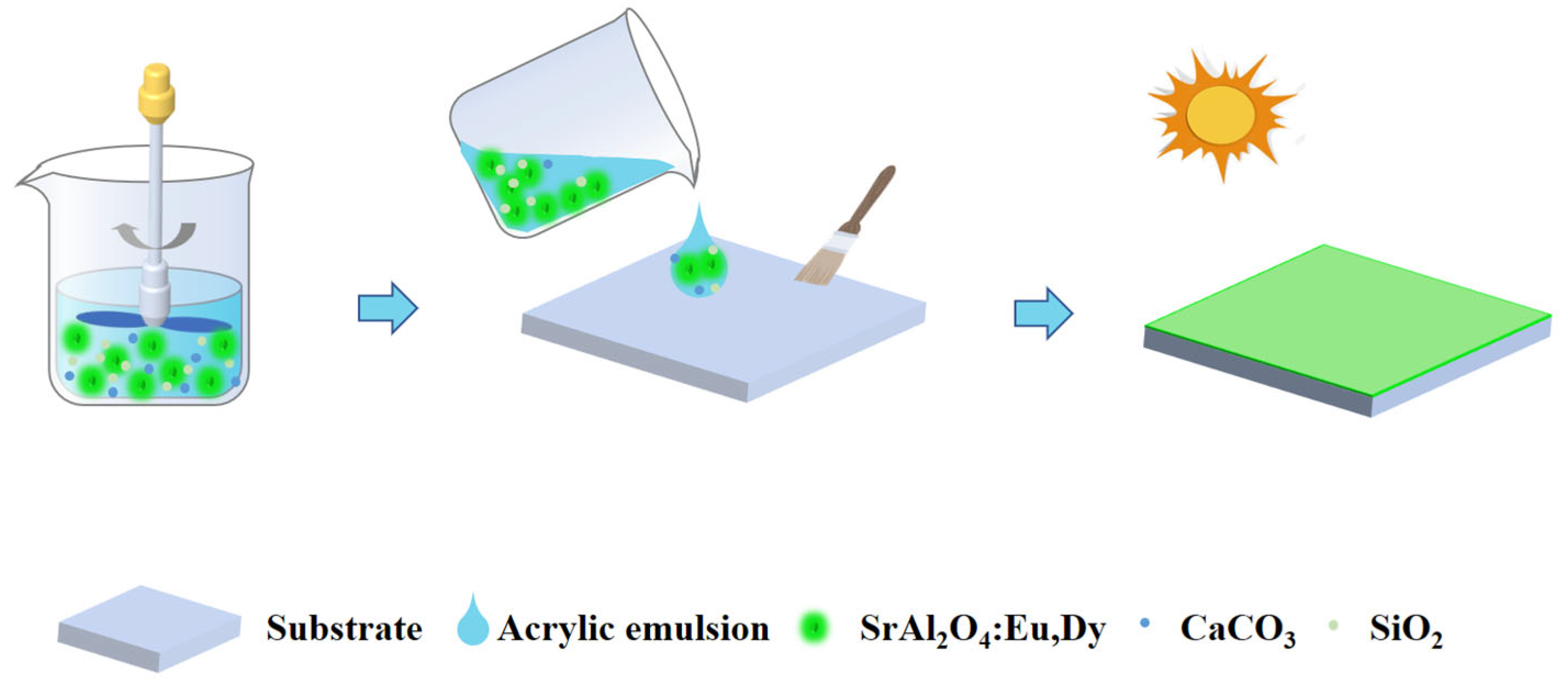
2.2. Preparation of Long Persistent Luminescent Coating

The film-forming substance was acrylic emulsion purchased from Hebei Taiji Chemical Industry Co. LTD (chemically pure, Hebei, China). The additives were a thickening agent, film-forming agent, anti-sedimentation agent and silane coupling agent purchased from Shenzhen Jitian Chemical Co. LTD (chemically pure, Shenzhen, China), and the fillers were SiO2 and CaCO3 purchased from Sinopharm Chemical Reagent Co. LTD (99.99% pure, Shanghai, China). First, the required reagents were weighed according to the raw material ratio. Using the blending method, water, thickening agent, SiO2 and CaCO3 were mixed and then mixed with acrylic emulsion and film-forming agent directly. After stirring for 10 min, SrAl2O4:Eu2+,Dy3+ phosphors, anti-sedimentation agent and silane coupling agent were added, following by stirring for 15 min, to obtain a green long persistent luminescent coating.

2.3. Characterization Techniques

The purity of the phase was measured by X-ray diffraction (XRD, Model SmartLab, Rigaku, Tokyo, Japan). The diffraction data were detected at 40 kV/40 mA, and the Cu Kα radiation was filtered by nickel. The scanning speed and scanning range were 10.0° 2θ/min and 10°–70°, respectively. The microscopic morphology of the samples was observed with field-emission scanning electron microscopy (FE-SEM, Model S-4800, Hitachi, Tokyo, Japan) at an acceleration voltage of 15 kV. The photoluminescence spectra, afterglow spectra and afterglow decay curves of phosphor and luminescent coating were measured by a Model JY FL3-21 spectrophotometer (Horiba, Kyoto). After exposure to a 365 nm UV light for 5 min at room temperature, the thermoluminescence glow curve of the phosphor was measured on a spectrometer (Model FJ-427A TL, Beijing Nuclear Instrument Factory, Beijing, China) at a heating rate of 1 K·s−1.

3. Results and Discussion

Figure 1a shows the XRD pattern of the SrAl2O4:Eu2+,Dy3+ phosphor. It can be seen that all diffraction peaks of the sample match well with the peaks of the standard diffraction of SrAl2O4 (JCPDS No. 34-0379), indicating that a pure phase sample has been obtained. The diffraction peaks are very sharp, which indicates the high crystallinity of the sample. Figure 1b shows the FE-SEM morphology of the SrAl2O4:Eu2+,Dy3+ phosphor, in which it can be seen that the selected particle size is approximately 15 μm. The elemental mapping results in Figure 1c confirm that all elements are evenly distributed in the particle. It is further proved that the sample obtained is a solid solution.
Figure 2a shows the photoluminescence excitation (PLE) and photoluminescence (PL) spectra of the SrAl2O4:Eu2+,Dy3+ phosphor. The PLE spectrum monitored at 522 nm contains a broad band from 300 nm to 500 nm, with the maximum at ~397 nm. Thus, the sample can be effectively excited by daylight or visible light. When excited by UV light at 397 nm, the sample exhibits a green emission with a peak at 522 nm, which is attributed to the 5d1–4f7 transition of Eu2+ [29]. Figure 2b shows the afterglow spectrum of the SrAl2O4:Eu2+,Dy3+ sample. The afterglow emission wavelength is 522 nm, which is assigned to the 5d1–4f7 transition of Eu2+ [30]. The CIE chromaticity diagram is utilized to analyze the afterglow emission color and indicates that the color is located in the green region with coordinate of (0.284, 0.543), as shown in Figure 2c. The afterglow decay curve in Figure 2d describes how the green afterglow of the sample can last more than 1000 s, which is detected at 522 nm after 5 min excitation by a 365 nm UV lamp. The afterglow phenomenon is determined by the existence of traps in the materials. The thermoluminescence (TL) curve is an important method to characterize the trap in phosphors [31]. In Figure 2e, the traps of the sample are tested and analyzed. The TL curve of phosphor covers a wide range from 320 K to 420 K, with two peaks centered at 342 K and 395 K. The following function is used to calculate the depth of the trap (E) [32]:
E = T m 500
where Tm is the temperature of the peak maximum in the TL curves (Kelvin temperature). The trap depths of the sample are 0.68 eV for 342 K and 0.79 eV for 395 K, respectively. Among them, the shallow trap at 0.68 eV leads to a high initial afterglow intensity and the deep trap at 0.79 eV leads to long lasting afterglow phenomena. After sunlight excitation for 2 h, a green afterglow lasting more than 8 h in the dark can be seen by the naked eye (Figure 2f). Therefore, SrAl2O4:Eu2+,Dy3+ can serve as a potential long afterglow luminescence material for application in a smart highway.
The green long persistent luminescent coating is prepared by using the blending method. Then, it is coated on the substrate and dried at room temperature to obtain the green luminescent coating (Figure 3), which can be tested and analyzed later.
As can be seen from the XRD pattern in Figure 4a, the diffraction peaks of green luminescent coating correspond exactly to the positions of the diffraction peaks of SrAl2O4:Eu2+,Dy3+ phosphor, but the peak intensity drops a lot [33,34]. The crystal structure of phosphor is not changed when SrAl2O4:Eu2+,Dy3+ phosphor is used to prepare luminescent coating. Therefore, the characterization and analysis of green luminescent coating can be carried out. Figure 4b shows an FE-SEM image of the cross section of green luminescent coating. The irregularly shaped particles of approximately 10–30 μm in the luminescent coating are SrAl2O4:Eu2+,Dy3+ phosphor, indicating that there is no agglomeration of phosphor during the preparation of luminescent coating [35,36]. The element mapping analysis (Figure 4c) is performed on the selected region of the luminescent coating cross section. It is shown that Sr, Al, C, Si and Ca elements are detected. Furthermore, the SrAl2O4:Eu2+,Dy3+ phosphor, SiO2 powder and filler CaCO3 are dispersed in the acrylic emulsion, and the green luminescent coating with uniform dispersion of each component is obtained.
Figure 5 shows cross sections of the morphology of the luminescent coating with different SiO2 contents. It can be seen that when the incorporation content is small, pores will be generated in the coating (Figure 5a), which will affect the compactness of the luminescence coating. If the content is too high, the components in the coating will gather (Figure 5e), which may affect the luminescence performance. Therefore, the proper addition of 1.25% SiO2 to the luminescence coating will make the coating more evenly dispersed (Figure 5d), and thus, make it achieve the best luminous effect [37,38].
The water absorption of a material is closely related to its porosity and pore structure characteristics. The water absorption of luminescent coatings with different CaCO3 contents are tested and calculated according to the following formula [39]:
m t = ( m 2 m 1 ) m 1 100 %
where mt is water absorption of the sample, m1 is mass of the sample before soaking and m2 is mass of the sample after soaking. It can be seen from Figure 6 that all curve trends are divided into two stages. At the initial stage, the water absorption of the luminescent coating increases rapidly with the increase in soaking time. After about five days, the water absorption of coatings basically no longer has a large change, reaching saturation. At the saturation stage, the water absorption of the luminescent coating mixed with 3.5% CaCO3 is the lowest, which is close to 26%. As depicted in Figure 6, the initial water absorption is nonlinearly fitted using Equation (3) [40]:
m t = K · t n
where mt is the water absorption of the coating at time t and K and n are constants. When the process exhibits ideal Fickian behaviour, n is equal to 0.5. The n values of the luminescent coatings with different CaCO3 contents are all close to 0.5. Therefore, the diffusion behavior of water in the coatings basically conforms to the ideal Fickian behavior. On this basis, the diffusion coefficient can be calculated using Equation (4) [41]:
m t m s = 4 D L π t
where mt is the water absorption of the coating at time t, ms is the water absorption of the coating when it is saturated, L is the coating thickness (cm) and D is the diffusion coefficient (cm2·s−1). Equation (4) shows that mt/ms is proportional to t1/2 and such that the diffusion coefficient can be obtained by linear fitting [42]. It can be seen from Figure 7 that with the increase in CaCO3 content, the diffusion coefficient increases first and then decreases, and the diffusion coefficient of the coating mixed with 3.5% CaCO3 is the lowest. Therefore, appropriate addition of CaCO3 will improve the density of the luminescent coating and reduce the water absorption. The hardness of the luminescent coating with 3.5% CaCO3 is 0.5 GPa, as tested by an automatic microhardness tester.
Figure 8 shows the PLE spectra, PL spectra, afterglow spectra and afterglow decay curves of luminescent coatings with different ratios of phosphor to emulsion. As shown in Figure 8a, the excitation spectra include a broad band centered around 397 nm. Therefore, the green luminescent coatings can be effectively excited by sunlight or visible light. In addition, under the excitation of 397 nm, the emission of the luminescent coating is a broad peak ascribed to the 5d1–4f7 transition of Eu2+. The optimal emission peak is located at 522 nm (Figure 8b). Theoretically, if the phosphor content of the luminescent coating is too small, its total emission intensity will be weak. With the increase in the amount of phosphor, the emission intensity of the coating will increase. The results obtained in this experiment correspond to that, with the decrease in the phosphor content, the intensity of the excitation and emission peaks of luminescent coatings decrease. After 5 min of irradiation by a 365 nm UV lamp, the afterglow spectra and afterglow decay curves of the green coatings with different ratios of phosphor to emulsion were analyzed. As shown in Figure 8c, the afterglow emission wavelength of all luminescent coatings is located at 522 nm. With the reduction of long afterglow phosphor contents, the intensity of the afterglow decreases. Figure 8d shows the afterglow decay curves of green luminescent coatings. All of the curves show a similar trend: the intensity of the afterglow decays very fast in the first few minutes and gradually slows down over time. Considering the practical application of luminescent coatings, the coating is exposed to sunlight for 2 h (Figure 8e). It can be clearly seen that the afterglow brightness of each coating darkens with the increase in time, and the afterglow time can last for more than 5 h. Due to the high price of long afterglow phosphor, if its use content is too large, the cost of luminescent paint will increase. Considering the luminescent effect and cost, this work shows that the best ratio of phosphor to emulsion is 1:2.
Figure S1 shows the PLE spectra, PL spectra, afterglow spectra and afterglow decay curves of luminescent coatings with different SiO2 contents. It can be seen that the addition of SiO2 does not affect the luminous color of the luminescent coating. Figure S1c shows the afterglow spectra and afterglow decay curves of the luminescent coatings. Incorporation of SiO2 with increasing concentrations from 0.5% to 1.25% causes an increase in the afterglow intensity. When the SiO2 content is 1.5%, the afterglow intensity decreases. This is because the components in the luminescent coatings are evenly dispersed when the 1.25% SiO2 powder is added, as shown in the above FE-SEM image in Figure 5d. Thus, SrAl2O4:Eu2+,Dy3+ phosphor can achieve the best luminous effect in the luminescent coating. Figure S1e shows the afterglow photos of the luminescent coating after sunlight excitation for 2 h which can prove that the afterglow brightness is the highest when 1.25% SiO2 is added, which corresponds to the above spectra. Therefore, the optimal incorporation of SiO2 is determined to be 1.25%.
Figure S2 shows the PLE spectra, PL spectra, afterglow spectra and afterglow decay curves of luminescent coatings with different CaCO3 contents. It can be seen that the peak shape and peak position of PLE/PL spectra do not change after the addition of CaCO3. With the increase in CaCO3 content, the intensity of the excitation and emission peaks of the coatings increase first and then decrease, and the luminescence reaches the highest intensity when the coating is mixed with 3.5% CaCO3. After 5 min of irradiation by a 365 nm UV lamp, the afterglow spectra and afterglow decay curves of luminescent coatings were obtained, as shown in Figure S2c,d. It can be seen that the afterglow emission wavelength is 522 nm. With the increase in CaCO3 content, the afterglow intensity of luminescent coatings first increases and then decreases. Figure S2e shows the afterglow images of the luminescent coating. With the increase in time, the brightness of the afterglow of the coating darkens, and the change of intensity corresponds to the afterglow decay curves. When 3.5% CaCO3 is added, luminescent coating has the best afterglow performance. The results show that when the coating has the best compactness, it has the highest afterglow intensity. Therefore, the optimum content of CaCO3 is determined to be 3.5%.
The water resistance of luminescent coating with different CaCO3 contents is systematically tested, as shown in Figure 9a. After soaking in water for 120 h, the surface of the coating is smooth without blistering. It can be seen from the afterglow emission spectra in Figure 9b that the afterglow emission of the coatings is located at 522 nm and the peak position does not change. Corresponding to the variation trend of the afterglow emission intensity of the coatings without soaking water, the afterglow intensity is the highest when 3.5% CaCO3 is added. Figure 9c shows the afterglow decay curves measured by the luminescent coatings doped with 3.5% CaCO3 soaked in water for different lengths of time. The afterglow intensity of the coating gradually decreases with the increase in soaking time. The inset in Figure 9c is the afterglow photo of the coating excited by the ultraviolet lamp at 365 nm after soaking for 120 h, which can still output a bright green afterglow. Figure 9d shows the change rate of the afterglow intensity obtained at different times. After soaking for 120 h, the afterglow intensity reaches 76% of the original at 1000 s, indicating that the luminescent coating has good water resistance and practical applicability.
Figure 10 shows the afterglow photos of the luminescent coating during daylight excitations on cloudy, sunny and rainy days in different weather. With the increase in time, there is little difference in the brightness of the afterglow obtained under different weather conditions, and the afterglow can last for more than 5 h. This shows that weather conditions have no effect on the intensity of the coating afterglow. Therefore, this kind of luminescent coating can meet the application requirements of a smart highway.

4. Conclusions

In this work, we successfully synthesized SrAl2O4:Eu2+,Dy3+ green long afterglow phosphor via high-temperature solid state reactions in a reducing atmosphere. The phosphor was used as a raw material to prepare a green long persistent luminescent coating using the blending method. The main methods of characterization were XRD, FE-SEM, PL/PLE, TL, afterglow spectra, afterglow decay curves and water absorption. The green phosphor calcined at 1350 °C has two traps of appropriate depths, a shallow trap (0.66 eV) and a deep trap (0.8 eV), showing good afterglow properties. After 2 h of sunlight excitation, the afterglow can reach more than 8 h. The optimum ratios of different substances in the long persistent luminescent coating were determined. The ratio of phosphor to emulsion is 1:2, and the incorporation amounts of SiO2 and CaCO3 are 1.25% and 3.5%, respectively. The addition of SiO2 improves the uniformity of each component in the coating and makes the coating achieve the best luminous effect. By adding CaCO3 to adjust its content, the compactness of the coating is improved, and the water absorption is reduced. After soaking for 120 h, the afterglow intensity decreased to 76% of the original. When it is applied in practice, the afterglow intensity of luminescent coatings is not significantly affected after daylight excitation in different weather conditions (cloudy, sunny, rainy), and can reach more than 5 h; therefore, it can be applied to a smart highway.

Supplementary Materials

The following supporting information can be downloaded at: https://www.mdpi.com/article/10.3390/coatings13061050/s1, Figure S1: (a) PLE spectra, and (b) PL spectra of luminescent coatings with different SiO2 contents. (c) Afterglow spectra, and (d) Afterglow decay curves of luminescent coatings with different SiO2 contents obtained after 5 min illumination with 365 nm UV light. (e)Afterglow images of luminescent coatings taken after sunlight excitation for 2 h with different SiO2 contents. Figure S2: (a) PLE spectra, and (b) PL spectra of luminescent coatings with different CaCO3 contents. (c) Afterglow spectra, and (d) Afterglow decay curves of luminescent coatings with different CaCO3 contents obtained after 5 min illumination with 365 nm UV light. (e) Afterglow images of luminescent coatings taken after sunlight excitation for 2 h with different CaCO3 contents.

Author Contributions

M.Z.: data curation, formal analysis. X.L.: data curation, formal analysis. Y.B.: data curation, formal analysis. S.T.: data curation. P.L.: data curation, formal analysis, writing—original draft. Q.Z.: resources, supervision, conceptualization, writing—review and editing, conceptualization. All authors have read and agreed to the published version of the manuscript.

Funding

Natural Science Foundation of Liaoning Province (Grant No. 2020-MS-081).

Institutional Review Board Statement

Not applicable.

Informed Consent Statement

Not applicable.

Data Availability Statement

Data available on request from the authors.

Acknowledgments

This work was supported in part by the Natural Science Foundation of Liaoning Province (Grant 2020-MS-081).

Conflicts of Interest

The authors declare no conflict of interest.

References

  1. Xu, J.; Tanabe, S. Persistent luminescence instead of phosphorescence: History, mechanism, and perspective. J. Lumin. 2018, 205, 581–620. [Google Scholar] [CrossRef]
  2. Hölsä, J. Persistent Luminescence Beats the Afterglow: 400 Years of Persistent Luminescence. Electrochem. Soc. Interface 2009, 18, 42–45. [Google Scholar] [CrossRef]
  3. Matsuzawa, T.; Aoki, Y.; Takeuchi, N.; Murayama, Y. A New Long Phosphorescent Phosphor with High Brightness, SrAl2O4: Eu2 +, Dy3 +. J. Electrochem. Soc. 1996, 143, 2670. [Google Scholar] [CrossRef]
  4. Jin, Y.; Hu, Y.; Chen, L.; Ju, G.; Wu, H.; Mu, Z.; He, M.; Xue, F. Luminescent properties of a green long persistent phosphor Li2MgGeO4:Mn2+. Opt. Mater. Express 2016, 6, 929–937. [Google Scholar] [CrossRef]
  5. Zhang, C.; Gong, X.; Cui, R.; Deng, C. Improvable luminescent properties by adjusting silicon-calcium stoichiometric ratio in long afterglow phosphors Ca1.94MgSi2O7:Eu2+0.01,Dy3+0.05. J. Alloys Compd. 2016, 658, 898–903. [Google Scholar] [CrossRef]
  6. Wang, C.; Jin, Y.; Lv, Y.; Ju, G.; Liu, D.; Chen, L.; Li, Z.Z.; Hu, Y. Trap distribution tailoring guided design of super-long-persistent phosphor Ba2SiO4:Eu2+,Ho3+ and photostimulable luminescence for optical information storage. J. Mater. Chem. C 2018, 6, 6058–6067. [Google Scholar] [CrossRef]
  7. Fu, X.; Liu, Y.; Meng, Y.; Zhang, H. Long afterglow green luminescence of Tb3+ ion in Ga4GeO8 through persistent energy transfer from host to Tb3+. J. Lumin. 2021, 237, 118149. [Google Scholar] [CrossRef]
  8. Wang, J.; Chen, W.; Peng, L.; Han, T.; Liu, C.; Zhou, Z.; Qiang, Q.P.; Shen, F.J.; Wang, J.; Liu, B. Long persistent luminescence property of green emitting Sr3Ga4O9:Tb3+ phosphor for anti-counterfeiting application. J. Lumin. 2022, 250, 119066. [Google Scholar] [CrossRef]
  9. He, X.; Zhang, H.; Xie, F.; Tao, C.; Xu, H.; Zhong, S. Enhanced afterglow performance of Zn2SiO4:Mn2+ by Pr3+ doping and mechanism. Ceram. Int. 2022, 13, 19358–19366. [Google Scholar] [CrossRef]
  10. Rojas-Hernandez, R.E.; Rubio-Marcos, F.; Rodriguez, M.Á.; Fernandez, J.F. Long Lasting Phosphors: SrAl2O4: Eu, Dy as the Most Studied Material. Renew. Sust. Energ. Rev. 2018, 81, 2759–2770. [Google Scholar] [CrossRef]
  11. Liepina, V.; Millers, D.; Smits, K. Tunneling Luminescence in Long Lasting Afterglow of SrAl2O4: Eu, Dy. J. Lumin. 2017, 185, 151–154. [Google Scholar] [CrossRef]
  12. Qiu, Z.F.; Zhou, Y.Y.; Lv, M.K.; Zhang, A.Y.; Ma, Q. Combustion Synthesis of Long-Persistent Luminescent MAl2O4: Eu2+, R3+ (M= Sr, Ba, Ca, R= Dy, Nd and La) Nanoparticles and Luminescence Mechanism Research. Acta Mater. 2007, 55, 2615–2620. [Google Scholar] [CrossRef]
  13. Luo, X.H.; Cao, W.H.; Xiao, Z.H. Investigation on the Distribution of Rare Earth Ions in Strontium Aluminate Phosphors. J. Alloys Compd. 2006, 416, 250–255. [Google Scholar] [CrossRef]
  14. Cordoncillo, E.; Julian-Lopez, B.; Martínez, M.; Sanjuán, M.L.; Escribano, P. New Insights in the Structure-Luminescence Relationship of Eu: SrAl2O4. J. Alloys Compd. 2009, 484, 693–697. [Google Scholar] [CrossRef]
  15. Peng, T.Y.; Yang, H.P.; Pu, X.L.; Hu, B.; Jiang, Z.C.; Yan, C.H. Combustion Synthesis and Photoluminescence of SrAl2O4: Eu, Dy Phosphor Nanoparticles. Mater. Lett. 2004, 58, 352–356. [Google Scholar] [CrossRef]
  16. Peng, T.Y.; Li, H.J.; Yang, H.P.; Yan, C.H. Synthesis of SrAl2O4: Eu, Dy Phosphor Nanometer Powders by Sol-Gel Processes and Its Optical Properties. Mater. Chem. Phys. 2004, 85, 68–72. [Google Scholar] [CrossRef]
  17. Zang, L.X.; Shao, W.H.; Kwon, M.S.; Zhang, Z.G.; Kim, J. Photoresponsive Luminescence Switching of Metal-Free Organic Phosphors Doped Polymer Matrices. Adv. Opt. Mater. 2020, 8, 2000654. [Google Scholar] [CrossRef]
  18. Poelman, D.; Van der Heggen, D.; Du, J.R.; Cosaert, E.; Smet, P. Persistent Phosphors for the Future: Fit for the Right Application. J. Appl. Phys. 2020, 128, 240903. [Google Scholar] [CrossRef]
  19. Chiatti, C.; Fabiani, C.; Pisello, A.L. Long Persistent Luminescence: A Road Map Toward Promising Future Developments in Energy and Environmental Science. Annu. Rev. Mater. Sci. 2021, 51, 409–433. [Google Scholar] [CrossRef]
  20. Wang, H.; Jasim, A.; Chen, X.D. Energy harvesting technologies in roadway and bridge for different applications-A comprehensive review. Appl. Energy 2018, 212, 1083–1094. [Google Scholar] [CrossRef]
  21. Wiese, A.; Washington, T.; Tao, B.; Weiss, W.J. Assessing performance of glow-in-the-dark concrete. Transp. Res. Record. 2015, 2508, 31–38. [Google Scholar] [CrossRef]
  22. Tian, Y.X.; Ma, B.; Liu, F.W.; Li, N.; Zhou, X.Y. Thermoregulation effect analysis of microencapsulated phase change thermoregulation agent for asphalt pavement. Constr. Build. Mater. 2019, 221, 139–150. [Google Scholar] [CrossRef]
  23. Gallego, J.; del Val, M.A.; Contreras, V.; Páez, A. Heating asphalt mixtures with microwaves to promote self-healing. Constr. Build. Mater. 2013, 42, 1–4. [Google Scholar] [CrossRef]
  24. Zhang, M.; Li, F.; Jiang, S.; Lin, Y.C.; Chen, F.; Zhao, X.; Shen, Y. CaAl2O4: Eu2+, Nd3+ Anti-Corrosive Coating and Its Afterglow-Catalytic Process. Opt. Mater. 2021, 116, 111049. [Google Scholar] [CrossRef]
  25. Bispo-Jr, A.G.; Lima, S.A.; Carlos, L.D.; Ferreira, R.A.; Pires, A.M. Phosphor-Based Green-Emitting Coatings for Circadian Lighting. J. Lumin. 2020, 224, 117298. [Google Scholar] [CrossRef]
  26. Xiong, G.; Zhang, Z.; Qi, Y. Effect of the Properties of Long Afterglow Phosphors on the Antifouling Performance of Silicone Fouling-Release Coating. Prog. Org. Coat. 2022, 170, 106965. [Google Scholar] [CrossRef]
  27. Al-Qahtani, S.D.; Al-nami, S.Y.; Alkhamis, K.; Al-Ahmed, Z.A.; Binyaseen, A.M.; Khalifa, M.E.; El-Metwaly, N.M. Simple Preparation of Long-Persistent Luminescent Paint with Superhydrophobic Anticorrosion Efficiency from Cellulose Nanocrystals and an Acrylic Emulsion. Ceram. Int. 2022, 48, 6363–6371. [Google Scholar] [CrossRef]
  28. Thejo Kalyani, N.; Jain, A.; Dhoble, S.J. Persistent Phosphors for Luminous Paints: A Review. Luminescence 2022, 37, 524–542. [Google Scholar] [CrossRef]
  29. Dutczak, D.; Jüstel, T.; Ronda, C.; Meijerink, A. Eu2+ Luminescence in Strontium Aluminates. Phys. Chem. Chem. Phys. 2015, 17, 15236–15249. [Google Scholar] [CrossRef] [Green Version]
  30. Korthout, K.; Van den Eeckhout, K.; Botterman, J.; Nikitenko, S.; Poelman, D.; Smet, P.F. Luminescence and X-ray Absorption Measurements of Persistent SrAl2O4: Eu, Dy Powders: Evidence for Valence State Changes. Phys. Rev. B 2011, 84, 085140. [Google Scholar] [CrossRef] [Green Version]
  31. Guo, C.F.; Tang, Q.; Zhang, C.X.; Huang, D.X.; Su, Q. Thermoluminescent Properties of Eu2+ and RE3+ Co-doped Phosphors CaGa2S4:Eu2+,RE3+ (RE=Ln, Excluding Pm, Eu and Lu). J. Lumin. 2007, 126, 333–338. [Google Scholar] [CrossRef]
  32. Van den Eeckhout, K.; Bos, A.J.; Poelman, D.; Smet, P.F. Revealing Trap Depth Distributions in Persistent Phosphors. Phys. Rev. B 2013, 87, 045126. [Google Scholar] [CrossRef] [Green Version]
  33. Poulose, A.M.; Shaikh, H.; Anis, A.; Alhamidi, A.; Kumar, N.S.; Elnour, A.Y.; Al-Zahrani, S.M. Long persistent luminescent hdpe composites with strontium aluminate and their phosphorescence, thermal, mechanical, and rheological characteristics. Materials 2022, 15, 1142. [Google Scholar] [CrossRef]
  34. Poulose, A.M.; Anis, A.; Shaikh, H.; Alhamidi, A.; Siva Kumar, N.; Elnour, A.Y.; Al-Zahrani, S.M. Strontium aluminate-based long afterglow pp composites: Phosphorescence, thermal, and mechanical characteristics. Polymers 2021, 13, 1373. [Google Scholar] [CrossRef]
  35. Wang, L.; Shang, Z.; Shi, M.; Cao, P.; Yang, B.; Zou, J. Preparing and testing the reliability of long-afterglow SrAl2O4:Eu2+,Dy3+ phosphor flexible films for temperature sensing. RSC Adv. 2020, 10, 11418–11425. [Google Scholar] [CrossRef] [PubMed] [Green Version]
  36. Lin, J.D.; Chen, C.C.; Lin, C.F. Influence of sol–gel-derived ZnO:Al coating on luminescent properties of Y2O3:Eu3+ phosphor. J. Sol-Gel Sci. Technol. 2019, 92, 562–574. [Google Scholar] [CrossRef]
  37. Shi, X.; Dou, R.; Ma, T.; Liu, W.; Lu, X.; Shea, K.J.; Song, J.L.; Jiang, L. Bioinspired lotus-like self-illuminous coating. ACS Appl. Mater. Interfaces 2015, 7, 18424–18428. [Google Scholar] [CrossRef]
  38. Wan, M.; Jiang, X.; Nie, J.; Cao, Q.; Zheng, W.; Dong, X.; Fan, Z.H.; Zhou, W. Phosphor powders-incorporated polylactic acid polymeric composite used as 3D printing filaments with green luminescence properties. J. Appl. Polym. Sci. 2019, 137, 48644. [Google Scholar] [CrossRef]
  39. Perez, C.; Collazo, A.; Izquierdo, M.; Merino, P.; Novoa, X.R. Characterisation of the Barrier Properties of Different Paint Systems: Part II. Non-Ideal Diffusion and Water Uptake Kinetics. Prog. Org. Coat. 1999, 37, 169–177. [Google Scholar] [CrossRef]
  40. Perez, C.; Collazo, A.; Izquierdo, M.; Merino, P.; Novoa, X.R. Characterisation of the Barrier Properties of Different Paint Systems: Part I. Experimental Set-Up and Ideal Fickian Diffusion. Prog. Org. Coat. 1999, 36, 102–108. [Google Scholar] [CrossRef]
  41. Zhang, J.T.; Hu, J.M.; Zhang, J.Q.; Cao, C.N. Studies of Impedance Models and Water Transport Behaviors of Polypropylene Coated Metals in NaCl Solution. Prog. Org. Coat. 2004, 49, 293–301. [Google Scholar] [CrossRef]
  42. Zhang, J.T.; Hu, J.M.; Zhang, J.Q.; Cao, C.N. Studies of Water Transport Behavior and Impedance Models of Epoxy-Coated Metals in NaCl Solution by EIS. Prog. Org. Coat. 2004, 51, 145–151. [Google Scholar] [CrossRef]
Figure 1. (a) XRD pattern and (b) FE-SEM image of the SrAl2O4:Eu2+,Dy3+ phosphor. (c) Elemental mapping images of Sr, Al, Eu and Dy for the selected particle.
Coatings 13 01050 g001
Figure 2. (a) PLE and PL spectra of SrAl2O4:Eu2+,Dy3+ phosphor, with inset showing the digital photo under 365 nm UV light irradiation of phosphor. (b) Afterglow spectrum, (c) CIE chromaticity coordinates, (d) afterglow decay curve and (e) TL glow curve of the SrAl2O4:Eu2+,Dy3+ phosphor obtained after 5 min illumination with 365 nm UV light. (f) Afterglow images of SrAl2O4:Eu2+,Dy3+ phosphor taken after sunlight excitation for 2 h.
Coatings 13 01050 g002
Figure 3. Schematic illustration of the preparation process of luminescent coating.
Coatings 13 01050 g003
Figure 4. (a) XRD patterns of SrAl2O4:Eu2+,Dy3+ phosphor and luminescent coating. (b) FE-SEM image for cross section of luminescent coating. (c) Elemental mapping images of C, Sr, Al, Si and Ca for the selected region.
Coatings 13 01050 g004
Figure 5. FE-SEM images of luminescent coating cross sections with different SiO2 contents: (a) 0.5%, (b) 0.75%, (c) 1%, (d) 1.25% and (e) 1.5%.
Coatings 13 01050 g005
Figure 6. Water absorption of luminescent coatings with different CaCO3 contents. The inset is the fitting diagram of water absorption.
Coatings 13 01050 g006
Figure 7. The relationship between water absorption and immersion time of luminescent coatings with different CaCO3 contents.
Coatings 13 01050 g007
Figure 8. (a) PLE spectra and (b) PL spectra of luminescent coatings with different ratios of phosphor to emulsion. (c) Afterglow spectra and (d) afterglow decay curves of luminescent coatings with different ratios of phosphor to emulsion obtained after 5 min illumination with 365 nm UV light. (e) Afterglow images of luminescent coatings taken after sunlight excitation for 2 h with different ratios of phosphor to emulsion.
Coatings 13 01050 g008
Figure 9. (a) Photographs of luminescent coatings with different CaCO3 contents after immersion in water. (b) Afterglow spectra of luminescent coatings with different CaCO3 contents after immersion in water for 120 h obtained with 5 min illumination of 365 nm UV light. (c) Afterglow decay curves of 3.5% CaCO3 doped luminescent coating after immersion in water for different lengths of time obtained after 5 min illumination with 365 nm UV light. The inset is the afterglow image of 3.5% CaCO3 doped luminescent coating after immersion in water for 120 h taken after 10 s illumination with 365 nm UV light. (d) The change rate of afterglow intensity of 3.5% CaCO3 doped luminescent coating after immersion in water for different lengths of time. The inset is the afterglow images at 1000 s after excitation.
Coatings 13 01050 g009
Figure 10. Afterglow images of luminescent coatings taken after sunlight excitation for 2 h in different weather conditions.
Coatings 13 01050 g010
Disclaimer/Publisher’s Note: The statements, opinions and data contained in all publications are solely those of the individual author(s) and contributor(s) and not of MDPI and/or the editor(s). MDPI and/or the editor(s) disclaim responsibility for any injury to people or property resulting from any ideas, methods, instructions or products referred to in the content.

