Abstract
In the continuous casting, the protective slag is coated on the surface of the molten steel, which is an important factor affecting the quality of the billet. The liquid slag layer on the surface of molten steel should be kept at an appropriate thickness to ensure a sufficient supply of liquid slag and to prevent slag from becoming entangled in the billet shell. Moreover, the consumption of protective slag should be appropriate to ensure stable liquid slag film thickness and uniform heat transfer between the casting billet and the mold. In this work, a two-dimensional numerical calculation model using volume of fluid method was established for the flow of protective slag, the Navier–Stokes equation was solved for the model, the consumption of protective slag during a vibration cycle was calculated, and the effects of factors such as casting speed, amplitude, and vibration frequency on the consumption of protective slag were explored. The results showed that when the casting speed increased from 1.2 m/min to 1.6 m/min, the consumption of protective slag per unit area decreased by about 4.76%, but the consumption of protective slag per unit length of the casting billet increased by about 26.98% within a vibration cycle. The consumption of protective slag per unit area and per unit billet length within a vibration cycle increased slightly with the increase of amplitude. The variation pattern of the consumption of protective slag with vibration frequency was not obvious. This model can provide theoretical basis and technical guidance for the design of protective slag, thereby improving the quality of steel billets in steel plants.
1. Introduction
During the continuous casting production process, the protective slag added to the surface of the molten steel absorbs heat and melts, forming a stable three-layer structure of powder slag layer, sintering layer, and liquid slag layer on the surface of the molten steel, which is an important factor affecting the quality of the casting billet [1]. The slag consumption is an important indicator for evaluating the lubrication performance of protective slag, and also an important parameter that affects the absorption of floating inclusions in the molten steel by protective slag. Low or high consumption of protective slag can easily cause uneven flow of liquid slag at the meniscus, resulting in uneven heat transfer of the initial solidified shell and defects on the surface of the casting billet. Low consumption of protective slag is more likely to cause bonding and steel leakage during continuous casting, affecting the normal operation of continuous casting production. The liquid slag filled in the gap between the mold and the billet solidifies on one side of the mold wall to form a solid slag film, which is basically non-consumable [2]. The protective slag on the side near the solidified shell remains liquid, and as the mold vibrates up and down and the shell continues to move down, the liquid slag is continuously carried out of the mold [3,4,5,6].
Numerous scholars have conducted extensive research on protective slag [7,8,9,10,11,12]. Yang [7] built a 1D analytical model for slag infiltration during continuous casting of steel to investigate the slag behavior in the mold-strand gap. The model showed that a converging slag film into the casting direction was required to open the mold–strand gap if compression was applied in between. Additionally, model calculations implied that higher slag consumption was achievable from non-sinusoidal mold oscillation by means of the increase of film thickness through longer positive pressure with higher peak pressure. Chen et al. [8] established a three-dimensional computational model, coupled with the large eddy simulation (LES) model and volume of fluid multiphase model, to investigate the two-phase flow and slag entrainment during steel bloom continuous casting. The result showed that the slag entrainment mainly occurred around the 1/4 width of the mold. The equivalent diameter of most slag droplets was 2–6 mm under the current casting condition. Liu et al. [9] built a Lagrangian tracking model combined with Eulerian multi-phase to predict the time-dependent argon–steel–slag–air quasi-four-phase flow inside a slab continuous casting mold. The complex interfacial momentum transfers between various phases were considered. A dimensionless value of H (ave)/h was proposed to describe the time-averaged level fluctuation of the slag–steel interface. The exposed slag eye near the SEN would be formed when the value of H (ave)/h is larger than similar to 0.4. Wang et al. [10] built a computational model of thermal behavior of the top-surface slag layers in continuous casting mold to interpret the thermal insulation of mold powder. The calculation results showed that slag consumption was one important factor influencing the temperature drop, while the casting speed had no obvious effect on it. With the increase in slag consumption, the temperature drop increased. Zhou et al. [11] established a three-dimensional finite-difference model to study heat transfer, fluid flow, and isothermal crystallization of mold slag during double hot thermocouple technique experiments. During the quenching stage, the mold slag temperature decreases with the cooled thermocouple. The temperature across the mold slag achieves a steady, nonlinear temperature profile during the holding stage. Bielnicki et al. [12] presented the results of laboratory experiments with the usage of a water model of continuous steel casting mold for slab casting. Results showed that the presence of mold powder should not be ignored in laboratory experiments of continuous steel casting in mold because to a certain extent, it changed the behavior and entrainment conditions of the oil layer. Wang et al. [13] performed numerical investigations on the breakup behavior of slag using the coupled level-set and volume of fluid methodology and gained deep insight into the breakup mechanism of the primary breakup and influence of gas Weber number and liquid Reynolds number on the primary breakup. Zhang et al. [14] established a full-size water model considered vibration. The results indicated that bubbles existed in the molten steel due to entrapment and the flow pattern was different from that of the full protection-poured mold.
Although scholars have conducted a large amount of research, most of the scholars focused on the flow characteristic of slag, but fewer research considered the vibration. So the factors influencing the consumption of protective slag under vibration was not clear. In this work, a two-dimensional numerical model for the flow of protective slag is built to exhibit the flow character of slag. The consumption of protective slag during a vibration cycle is calculated, and the effects of factors such as casting speed, amplitude, and vibration frequency on the consumption of protective slag are explored. This model can provide theoretical basis and technical guidance for the design of protective slag, thereby improving the quality of steel billets in steel plants. Based on the results, the casting speed, frequency, and amplitude are controlled in a rational range; the billet quality improves; and few longitudinal cracks occur in the steel plants.
2. Model
The calculation area of this work is taken as 45 mm above and below the top of the meniscus, and the distance from the mold to it is 20 mm, as shown in Figure 1. This work focuses on the flow characteristic in the meniscus. The 45 mm above and below the top of meniscus could ensure that the slag and steel are all included in the model. The initial gap between mold and billet is always less than 10 mm near the meniscus region, so 20 mm from the mold could ensure the slag in the gap and the molten steel are all included in the model. The VOF (volume of fluid model) is used to track the fluctuation of the liquid slag/steel interface in the meniscus region. By solving the Navier–Stokes equation for the model, the transient flow of the protective slag in the meniscus region is simulated and calculated.
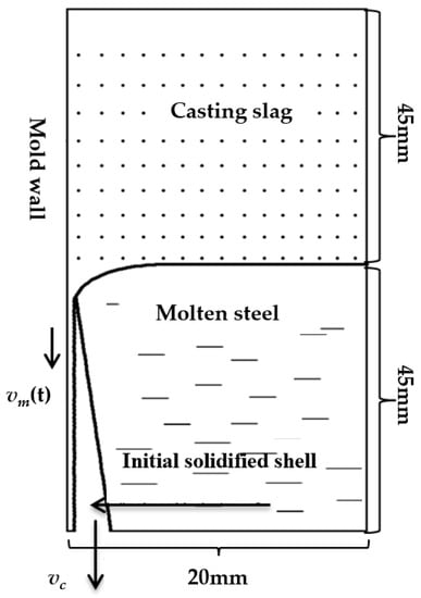
Figure 1.
Description of model domain in meniscus region.
2.1. Governing Equation
2.1.1. Volume of Fluid Equation
Due to the immiscibility of protective slag and molten steel, the VOF model is used to solve the interface problem between the two phases. In any control unit, the sum of the volume fraction of molten steel αst and molten slag αsl is 1. Therefore, there are three possibilities within the unit:
- αst = 1. The unit is filled with liquid slag and there is no steel liquid present.
- 0 < αst < 1. The unit is a two-phase mixing zone.
- αst = 0. The unit is filled with molten steel without any slag.
Tracing the interface between two phases is achieved by solving the continuity equation for the volume fraction of a single phase. For protective slag αst, the Equation (1) is as follows [15]:
Here, is the velocity component. The calculation of the volume fraction of protective slag αsl is based on the following constraints. αsl is calculated through Equation (2):
The density ρm and viscosity μm of the fluid within the control unit are functions of volume fraction, as shown in the Equations (3) and (4):
Here, and are the densities of protective slag and molten steel, respectively. and are the viscosities of protective slag and molten steel, respectively.
2.1.2. Continuity Equation [16]
The continuity equation indicates that the change in the total quantity of a property is due to the quantity flowing out through the volume boundary and the loss or gain of sources or sinks within the boundary. The continuity equation is expressed as Equation (5):
Here, is a function of the volume fraction and density of each phase, which is expressed as Equation (6):
2.1.3. Momentum Equation
The momentum equation is a specific application of the momentum theorem in fluid mechanics, where the magnitude of the external force acting on an object is equal to the rate of change of the momentum of the object in the direction of force action [17]. The momentum equation is shown as Equation (7):
Here, g is the gravitational acceleration. is the power source term; it is a function of the interfacial tension between the two phases and the average density within the unit.
2.1.4. Turbulence Model [18]
The flow model of protective slag needs to fully consider the impact of mold vibration on the flow of protective slag, which requires high-wall conditions. Therefore, the shear stress SST k-w model is chosen.
The calculation equations for the turbulent pulsation kinetic energy k and the dissipation rate w of turbulent pulsation kinetic energy are shown as Equations (8) and (9):
Here, is the generation coefficient of turbulent kinetic energy caused by the average velocity gradient, which is expressed in Equation (10). and are the effective diffusion terms and are shown in Equations (11) and (12), respectively:
Here, and are the turbulent Prandtl numbers and are shown as Equations (13) and (14), respectively. is the turbulent viscosity coefficient, as shown in Equation (15).
Here, S is the surface tension coefficient, as shown in Equation (17):
where F1 and F2 are the blending functions, as shown in Equations (18) and (19):
where y is the distance to the nearby surface. is the positive direction of the orthogonal divergence term, as shown in Equation (20):
2.1.5. Meniscus Contour Equation
The initial steady-state interface between liquid slag and molten steel is given by the Bikerman equation [19], as shown in Equations (21) and (22):
Here, x is the horizontal distance from the contact point of the two phases in the horizontal direction. y is the vertical distance from the highest point of the two adjacent contact surfaces. σ is the interfacial tension. g is the gravitational acceleration. is the density of molten steel. is the density of liquid slag.
2.2. Assumptions
The established model aims to calculate the flow behavior of liquid slag in the meniscus region. For the convenience of calculation, the following assumptions are made:
- The flow of molten steel and protective slag is an incompressible steady-state flow.
- The natural convection caused by density is ignored.
- Due to the small calculation area of the model, the thickness of the slag film and the initial shell remain unchanged.
- The flow of molten steel in the meniscus area is mainly influenced by the casting speed and the flow of protective slag.
- The gap between the casting billet and the mold is filled with liquid slag, the flow velocity of liquid slag perpendicular to the drawing direction is ignored.
2.3. Boundary Condition
- Upper surface of protective slag: Pressure inlet boundary with a pressure value of 1 atm.
- Gap outlet: Pressure outlet boundary with a pressure value of 1 atm.
- Mold wall: Sinusoidal vibration.
- Initial solidification shell: Move at the casting speed.
- Right boundary of the model: No-slip boundary with an isotropic velocity of 0. It is set as a symmetric boundary.
The calculated parameters are listed in Table 1. Based on the continuous casting production experience of steel mills, the chosen frequency and amplitude can ensure the smooth detachment of the billet from the mold. Meanwhile, the quality of the billet is relatively better under this parameter.

Table 1.
The parameters of the model.
3. Results and Discussion
3.1. Flow Velocity of Protective Slag on the Cross Section of the Slag Channel
Different positions with the same spacing in the thickness direction of the liquid slag film were chosen, including five nodes, where Node 1 was the contact position between the protective slag and the mold, Node 2 was adjacent to node 1, Node 3 was adjacent to Node 2, Node 4 was adjacent to Node 3, and Node 5 was the contact position between the liquid slag and the initial solidification shell, the distance between each node was the same. The velocity variation pattern of each node in a vibration cycle was shown in Figure 2. Among them, the speed of Node 1 was equal to the vibration speed of the mold, and the speed of Node 5 was equal to the casting speed. A positive flow rate indicated that the protective slag flows upwards, meaning that the gap between the protective slag and the consumption of the protective slag was negative. On the contrary, a negative value indicated that the protective slag flowed downwards; that is, the protective slag flowed into the gap and the consumption was positive. The liquid protective slag near the solidification shell flowed downward from the crystallizer as the billet moved. The inflow/outflow state of liquid protective slag near the solid slag film layer was mainly affected by the up-and-down vibration of the mold. It was observed that during the period of positive detachment, the flow velocities of liquid slag at Nodes 2, 3, and 4 were positive for some time, but there were also negative values, indicating that there were cases of liquid slag both entering and exiting the gap during the period of positive detachment. During the negative slip period, due to the negative velocity, there was no gap for the flux to flow out, and the flux always flowed in and consumed downwards during this period. The calculation results in this article are consistent with those of Ramirez-Lopez et al. [20], Meng et al. [21], and Zhu et al. [22].
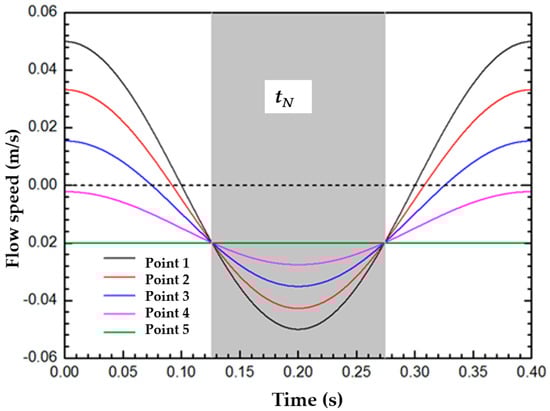
Figure 2.
Velocity distribution at transverse section of slag film.
3.2. Average Flow Velocity of Protective Slag
The flow velocity of different nodes within a vibration cycle along the thickness direction of the liquid slag was calculated, based on this, the average flow velocity of the protective slag was calculated, as shown in Figure 3. At t1, , the average flow velocity of protective slag on the cross section of the slag channel was 0, the amounts of protective slag flowing out and into the gap were equal, and the consumption of protective slag was 0. Afterwards, the inflow of protective slag was greater than the outflow, and the protective slag was carried out of the crystallizer with the solidification shell. At t2 = 0.126 s, the negative slip motion began, and under the combined action of the downward movement of the crystallizer and the negative pressure in the slag channel, the protective slag flowed into the gap. When t = t4, the inflow and outflow of protective slag reached a balance. When t > t4, the average flow velocity of the protective slag was positive; that is, the liquid slag flowed out of the gap upwards, and the slag consumption was negative. From this, it could be seen that within the time range t1~t4, at this point , the average flow rate of liquid slag was negative and would flow downwards into the gap between the mold and the shell. When the mold vibrated downwards at its maximum speed, the flow velocity reached its maximum value of 0.0351 m/s. When , the upward outflow of protective slag was higher than the inflow, and its contribution to slag consumption was negative. Therefore, in both positive and negative slip states, there was a positive consumption of protective slag. The consumption stage of protective slag existed from the end of positive slip to the early stage of the next positive slip state and included the entire negative slip time, which was consistent with previous research results [23,24].
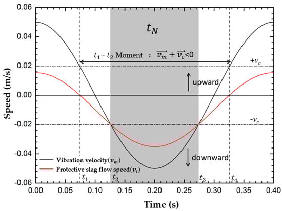
Figure 3.
The mean velocity of liquid slag at transverse section of slag film during one oscillation cycle.
3.3. Calculation Method of Slag Consumption
According to the conservation of mass, the calculation formula for the consumption of protective slag in the two-dimensional plane of the slag channel is as shown in Equations (23) and (24):
Here, Qs is the consumption of protective slag per unit area. Qcycle is the consumption of protective slag per unit length of casting billet within a vibration cycle. is the average flow velocity of liquid protective slag. dl is the thickness of the liquid slag film. W and N represent the width and thickness of the casting billet, respectively.
3.4. Discussion on Factors Affecting the Consumption of Protective Slag
The consumption of protective slag is an important indicator for evaluating the lubrication performance of protective slag. The consumption of protective slag per unit area (kg/m2) and the consumption of protective slag per unit length of the casting billet within a vibration cycle (g/m·cycle) are used to represent it. The recommended value of slag consumption is below 0.3 kg/m2. The flow rate of protective slag will change with changes in process parameters, such as speed, frequency and amplitude. To further investigate the impact of changes in casting speed, vibration frequency, amplitude, and other factors on the consumption of protective slag, three sets of calculation examples were used in this paper, and the calculation results are shown in Table 2.
Table 2.
Influence of different casting parameters on slag consumption.
3.4.1. Influence of Casting Speed on Slag Consumption
The variation of the consumption of protective slag with the casting speed was shown in Figure 4. As the casting speed increased, the consumption of protective slag per unit area decreased, but the decrease in protective slag was relatively small. It could be seen that when the casting speed increased from 1.2 m/min to 1.6 m/min, the consumption of protective slag per unit area only decreased by 4.76%, from 0.246 kg/m2 to 0.234 kg/m2. However, the consumption of protective slag per unit length of casting billet during a vibration cycle increased from 1.968 g/m·cycle to 2.499 g/m·cycle, an increase of approximately 26.98%. When the casting speed increased, the frictional resistance of the mold increased, making it more difficult for the protective slag to flow into the gap between the mold and the casting billet, and the thickness of the slag film became thinner. Therefore, the consumption of protective slag per unit area decreased. Many scholars have observed that when the mold is in sinusoidal or non-sinusoidal motion, the consumption of protective slag decreases with the increase in casting speed [25]. The findings of this article are consistent with previous research.
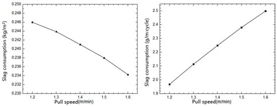
Figure 4.
Influence of casting speed on slag consumption.
3.4.2. Influence of Amplitude on Slag Consumption
Based on the C group calculation example in Table 2, the relationship between the consumption of protective slag and the amplitude change is shown in Figure 5. The amplitude increased from 2 mm to 4 mm, and the consumption of protective slag per unit area increased by 3.52%. The consumption of protective slag per unit area increased slightly with the increase of amplitude. The consumption of protective slag per unit billet length increased from 1.934 g/m·cycle to 2.002 g/m·cycle. From the results, the slag consumption per unit area, periodic vibration slag consumption, and amplitude were basically linearly related. As the amplitude increased, the gap between the mold and the billet increased, leading to more protective slag flowing into the gap between the mold and the billet, resulting in an increase in the consumption of protective slag. The calculation results in this article are consistent with Meng et al. [21].
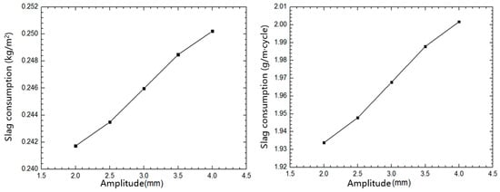
Figure 5.
Influence of oscillating stroke on slag consumption.
3.4.3. Influence of Frequency on Slag Consumption
The effect of vibration frequency change on the consumption of protective slag is calculated, as shown in Figure 6. The vibration frequency changed from 120 cpm to 160 cpm, an increase of about 33.3%. The consumption of protective slag per unit area showed a trend of first decreasing and then increasing, while the consumption of protective slag per unit length of casting billet gradually decreased within a vibration cycle, decreasing by about 24.6%. As the vibration frequency increased, the amount of protective slag flowing between the mold and the billet per unit time decreased. Therefore, as the vibration frequency increased, the consumption of protective slag showed a decreasing trend. However, if the vibration frequency continued to increase, there may be an increase in the consumption of protective slag. The calculation results in this article are consistent with Meng et al. [21].
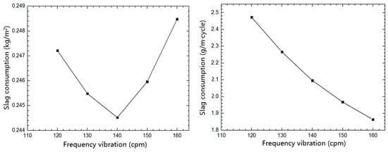
Figure 6.
Influence of oscillating frequency on slag consumption.
As determined by conducting variance analysis on the consumption of protective slag by speed, amplitude, and vibration frequency, the mean square deviations of speed, amplitude, and vibration frequency are 0.0046, 0.0015, and 0.0035, respectively. Speed is the most influential parameter.
4. Conclusions
By calculating the two-dimensional numerical model of the flow of protective slag in the meniscus region, the flow velocity, average flow velocity, and consumption of protective slag at each node on the cross-section of the slag channel were determined. The specific conclusions are as follows:
- The inflow and outflow states of protective slag on the cross-section of the slag film are related to the vibration parameters of the mold and the casting speed. During the positive slip period, there is a reflux of protective slag. During the negative slip period, the protective slag continues to flow into the gap. When ,the inflow and outflow of protective slag in the gap reach a balance. When ,the average flow rate of liquid slag is negative and will flow downwards into the gap between the mold and the shell. When the mold vibrates downwards at its maximum speed, the flow velocity reaches its maximum value. When , the outflow of protective slag is higher than the inflow, the contribution to slag consumption is negative, indicating non-slag consumption time. The consumption of protective slag occurs from the end of positive slip to the early stage of the next positive slip state and includes the entire negative slip stage.
- As the casting speed increases, the consumption of protective slag per unit area decreases. When the casting speed increases from 1.2 m/min to 1.6 m/min, the casting speed increases by about 33.3% and the consumption of protective slag per unit area decreases by about 4.76%. However, the consumption of protective slag per unit casting length within a vibration week increases by about 26.98%.
- The consumption of protective slag per unit area and per unit billet length within a vibration cycle increases slightly with the increase of amplitude. The variation pattern of the consumption of protective slag with vibration frequency is not obvious.
In this work, the consumption of protective slag during a vibration cycle is calculated, and the effects of factors such as casting speed, amplitude, and vibration frequency on the consumption of protective slag are explored. Based on the results, the casting speed, frequency, and amplitude are controlled in a rational range. Additionally, the billet quality improves, and few longitudinal cracks occur in the steel plants. Because continuous casting has different steel grades and different physical parameters, different components of protective slag are required to match the steel. At the same time, the shape of the billet also affects the flow of protective slag. Therefore, it is necessary to study different steel grades, billets, and protective slag. In future research, the relationship between different types of protective slag and process parameters for different continuous casting caster and steel grades will be further explored.
Author Contributions
Data curation, S.W. and G.Z.; writing—original draft, F.D. All authors have read and agreed to the published version of the manuscript.
Funding
This research received no external funding.
Institutional Review Board Statement
Not applicable.
Informed Consent Statement
Not applicable.
Data Availability Statement
Not applicable.
Conflicts of Interest
The authors declare no conflict of interest.
References
- Zhao, P.; Li, Q.; Kuang, S.B.; Zou, Z.S. Mathematical modeling of liquid slag layer fluctuation and slag droplets entrainment in a continuous casting mold based on vof-les method. High Temp. Mater. Process. 2017, 36, 551–565. [Google Scholar] [CrossRef]
- Liu, Z.Q.; Li, L.M.; Li, B.K. Modeling of gas-steel-slag three-phase flow in ladle metallurgy: Part I. Physical modeling. ISIJ Int. 2017, 57, 1971–1979. [Google Scholar] [CrossRef]
- Xu, L.; Pei, Q.W.; Han, Z.F.; Wang, E.A.; Wang, J.Y.; Karcher, C. Modeling study of EMBr effects on molten steel flow, heat transfer and solidification in a continuous casting mold. Metall. Res. Technol. 2023, 120, 218. [Google Scholar] [CrossRef]
- Swain, A.N.S.S.; Ganguly, S.; Sengupta, A.; Chacko, E.Z.; Dhakate, S.; Pandey, P.K. Investigation of corner cracks in continuous casting billet using thermomechanical model and plant measurements. Met. Mater. Int. 2022, 28, 2434–2447. [Google Scholar] [CrossRef]
- Suzuki, M.; Nakamoto, M.; Tanaka, T.; Tsukaguchi, Y.; Mishima, K.; Hanao, M. Effect of sulfur in slag on dynamic change behavior of liquid iron/molten slag interfacial tension. ISIJ Int. 2020, 60, 2332–2338. [Google Scholar] [CrossRef]
- Yu, X.; Wen, G.H.; Tang, P.; Ma, F.J.; Wang, H. Behavior of mold slag used for 20mn23al nonmagnetic steel during casting. J. Iron Steel Res. Int. 2011, 18, 20–25. [Google Scholar] [CrossRef]
- Yang, H. A 1D analytical model for slag infiltration during continuous casting of steel under non-sinusoidal mold oscillation. Metals 2020, 10, 1389. [Google Scholar] [CrossRef]
- Chen, W.; Zhang, L.F.; Wang, Y.D.; Ji, S.; Ren, Y.; Yang, W. Mathematical simulation of two-phase flow and slag entrainment during steel bloom continuous casting. Powder Technol. 2021, 390, 539–554. [Google Scholar] [CrossRef]
- Liu, Z.Q.; Sun, Z.B.; Li, B.K. Modeling of quasi-four-phase flow in continuous casting mold using hybrid Eulerian and Lagrangian approach. MMTB 2017, 48, 1248–1267. [Google Scholar] [CrossRef]
- Wang, Q.; Wu, Y.M.; Qiu, S.T.; Zhao, P. Simulation of thermal insulation of top-surface slag layers in continuous casting mold. J. Iron Steel Res. Int. 2012, 18, 29–33. [Google Scholar] [CrossRef]
- Zhou, L.J.; Wang, W.L.; Liu, R.; Thomas, B.G. Computational modeling of temperature, flow, and crystallization of mold slag during double hot thermocouple technique experiments. MMTB 2013, 44, 1264–1279. [Google Scholar] [CrossRef]
- Bielnicki, M.; Jowsa, J. Physical modeling of mold slag entrainment in continuous steel casting mold with consideration the impact of mold powder layer. Steel Res. Int. 2018, 89, 1800110. [Google Scholar] [CrossRef]
- Wang, L.L.; Zhang, Y.Z.; Long, Y.; Ke, H.B. Simulation of primary breakup of molten slag in the gas quenching dry granulation process. Appl. Therm. Eng. 2020, 25, 115850. [Google Scholar] [CrossRef]
- Zhang, L.L.; Chen, D.F.; Long, M.J.; Chen, H.B.; Huang, Y.W.; Dong, Z.H. Study on the fluid flow in a semi-open-stream-poured beam blank continuous casting mold with submerged refractory funnels by multiphase modeling. Metals 2016, 6, 104. [Google Scholar] [CrossRef]
- Li, L.M.; Liu, Z.Q.; Cao, M.X.; Li, B.K. Large eddy simulation of bubbly flow and slag layer behavior in ladle with discrete phase model (DPM)-volume of fluid (VOF) coupled model. JOM 2015, 67, 1459–1467. [Google Scholar] [CrossRef]
- Zhang, X.W.; Jin, X.L.; Wang, Y.; Deng, K.; Ren, Z.M. Comparison of standard k-ε model and RSM on three dimensional tur-bulent flow in the SEN of slab continuous caster controlled by slide gate. ISIJ Int. 2011, 51, 581–587. [Google Scholar] [CrossRef][Green Version]
- Brackbill, J.U.; Kothe, D.B.; Zemach, C. A continuum method for modeling surface tension. J. Comput. Phys. 1992, 100, 335–354. [Google Scholar] [CrossRef]
- Menter, F.R. Two-equation eddy-viscosity turbulence models for engineering applications. AIAA J. 1994, 32, 1598–1605. [Google Scholar] [CrossRef]
- Bikerman. Phisical Surfaces; Acadamic Press: London, UK, 1970. [Google Scholar]
- Ramirez-Lopez, P.E.; Lee, P.D.; Mills, K.C. Explicit modelling of slag infiltration and shell formation during mould oscillation in continuous casting. ISIJ Int. 2010, 50, 425–434. [Google Scholar] [CrossRef]
- Meng, X.N.; Zhu, M.Y. Analysis of liquid flux consumption mechanism for slab continuous casting mold with high casting speed. Acta Metall. Sin. 2009, 45, 485–489. [Google Scholar] [CrossRef]
- Zhu, L.G.; Jin, S.T. Numerical calculation on the flowing behaviour of mold fluxes between mold and shell. J. Iron Steel Res. 1998, 10, 9–12. [Google Scholar] [CrossRef]
- Shin, H.J.; Kim, S.H.; Thomas, B.G.; Lee, G.G.; Park, J.M.; Sengupta, J. Measurement and prediction of lubrication, powder consumption, and oscillation mark profiles in ultra-low carbon steel slabs. ISIJ Int. 2006, 46, 1635–1644. [Google Scholar] [CrossRef]
- Okazawa, K.; Kajitani, T.; Yamada, W.; Yamamura, H. infiltration phenomena of molten powder in continuous casting derived from analysis using Reynolds equation: Part 1: Steady analysis. ISIJ Int. 2006, 46, 234–240. [Google Scholar] [CrossRef][Green Version]
- Saraswat, R.; Fox, A.B.; Mills, K.C.; Lee, P.D.; Deo, B. The factors affecting powder consumption of mould fluxes. Scand. J. Metall. 2004, 33, 85–91. [Google Scholar] [CrossRef]
Disclaimer/Publisher’s Note: The statements, opinions and data contained in all publications are solely those of the individual author(s) and contributor(s) and not of MDPI and/or the editor(s). MDPI and/or the editor(s) disclaim responsibility for any injury to people or property resulting from any ideas, methods, instructions or products referred to in the content. |
© 2023 by the authors. Licensee MDPI, Basel, Switzerland. This article is an open access article distributed under the terms and conditions of the Creative Commons Attribution (CC BY) license (https://creativecommons.org/licenses/by/4.0/).