Article

Sintering-Induced Failure Mechanism of Thermal Barrier Coatings and Sintering-Resistant Design

School of Materials Science and Engineering, Xi’an Shiyou University, Xi’an 710065, China
*
Author to whom correspondence should be addressed.
Coatings 2022, 12(8), 1083; https://doi.org/10.3390/coatings12081083
Submission received: 30 June 2022 / Revised: 20 July 2022 / Accepted: 28 July 2022 / Published: 31 July 2022

Abstract

:
Thermal barrier coatings (TBCs) have been developed to protect superalloys against high-temperature heat fluxes, which are required for the development of high-performance gas turbines. TBCs have porous structures, which are densified by sintering. The resulting stiffening is a major cause of TBC failure in service. Therefore, there is a need to reduce the negative sintering effect on the life span of TBCs. In this study, the sintering mechanism and the dominant factors causing changes in stiffening and mechanical properties were revealed experimentally. The experimental results show that the multiscale undulation of the originally smooth two-dimensional (2D) pore inner surface triggers multipoint contact between the upper and lower inner surfaces, resulting in pore healing during thermal exposure. The healing of 2D pores is the main structural characteristic change in TBCs after thermal exposure and the main reason for the stiffening and changes in mechanical properties. Then, the sintering effect on TBCs with vertically cracked structures was designed and simulated. We found that implanting vertical cracks in the topcoat can reduce the sintering effect and driving force for cracking by 87.9% and 79.9%, respectively. The degree of reduction depends on the space between vertical cracks. Finally, the mechanism responsible for the sintering-resistant TBCs was analyzed and discussed. Vertically cracked structures exhibited scale-sensitive stiffening, indicating that macroscopic stiffening is much lower than microscopic stiffening. In other words, the macroscopic sintering effect was lowered, and the TBCs remained highly resistant to global strain during thermal exposure. The resulting strain energy release rates are much lower than those of conventional TBCs. The results of this study contribute to the long-life thermal protection of superalloy-based components used in advanced gas turbines.

1. Introduction

Recently, thermal barrier coatings (TBCs) have been widely employed in hot path components of gas turbines [1,2,3,4]. The basic structure of TBCs consists of three layers, including a ceramic topcoat (TC), metallic bond coat (BC), and metal substrate (SUB) [5,6,7]. TC provides thermal insulation and is made of ceramic materials with low thermal conductivity. BC provides oxidation resistance for the substrate and reduces the thermal expansion mismatch between TC and the underlying substrate [8,9,10,11,12]. TBCs prevent direct heat flux and reduce the metal exposed temperature. Thus, TBCs make the underlying metallic components efficiently work at temperatures higher than their limit [5,13]. Therefore, TBCs are an effective measure to significantly improve the efficiency of gas turbines and promote the development of aerospace and other fields [14].
Plasma spraying is the main method for depositing TBCs. In the plasma spraying technique, the hot high-velocity flame of a plasma gun is employed to convert spraying powders into molten droplets, which are impacted onto the substrate and finally stacked to form coatings [15,16]. Compared with other spraying techniques, plasma spraying is fast and has a high deposition efficiency. Plasma-sprayed coatings often have lamellar structures and contain many intersplat pores and intrasplat cracks [17,18]. The former is attributed to the imperfect bonding among splats, and the latter is caused by the tensile effect during the quenching process. The intersplat pores and intrasplat cracks exhibit two-dimensional (2D) morphology, which means that their dimensions in two directions are much larger than those in the third direction. In addition to 2D cracks, some globular voids are found in plasma-sprayed coatings. They are often caused by rough surfaces used to support droplets and entrapped plasma gas. The 2D and 3D pores endow plasma-sprayed coatings with high performances. The thermal conductivity and elastic modulus of the coatings are less than 50% compared with those of the corresponding bulk materials [17,19,20,21]. The porous structure can effectively prevent heat flux, resulting in required temperature drops with a certain thickness. In addition, it enhances strain tolerance, reducing thermal stress during thermal cycling. Selecting the right materials and manufacturing processes can produce coatings with high toughness and resistance to impact and corrosion [22,23,24]. Plasma-sprayed coatings exhibit excellent comprehensive performances. However, the structure cannot efficiently release stress, especially stress in a direction perpendicular to the direction of spray. During thermal cycling, TBCs experience failure through spallation or delamination. In heating and cooling processes, complex stress fields can be induced in TC. Furthermore, there are several unbonded regions, pores, and microcracks inside the coatings [25], which are equivalent to prefabricated cracks [26]. When tensile stress in coatings reaches the critical value, the cracks expand. TBCs are extremely prone to cracking within TC [27,28]. Owing to these issues, TBCs undergo spalling failure during service.
Cracking is highly related to the stiffening of TC caused by sintering. After thermal exposure, the elastic modulus of TC increases by two to three times [17,29,30]. Thus, the strain tolerance decreases significantly, which affects the durability of TBCs. In addition, the thermal conductivity is increased by 50–100%, meaning that the thermal insulation is significantly reduced [31]. Sintering is one of the main causes of performance degradation, resulting in the spalling failure of coatings in service. The corresponding structural change recorded during sintering is mainly the healing of intersplat pores and the intrasplat cracks. Since TC has a complex porous structure, sintering in the TC layer is inevitable under high temperatures. Therefore, it is significant to develop degradation-resistant TC structures to extend the life span of TBCs.
Degradation can be minimized by lowering the global stiffening effect since it mainly controls the cracking behavior of TBCs under stress [32,33]. The elastic modulus of plasma-sprayed coatings is scale-sensitive, that is, the macroscopic elastic modulus of TC is smaller than the microscopic elastic modulus [29]. This is because, in addition to the intrinsic intersplat pores and intrasplat cracks in the microscale, there are some large-scale cracks in the coatings. Intersplat pores and intrasplat cracks have a comparable scale with splat segments, whereas the large-scale cracks can cover several splat segments due to the rough surface and other factors. Thus, the presence of large-scale cracks further reduces the macroscopic elastic modulus. Based on this, the overall stiffening of coatings caused by sintering can be weakened by tailoring the macrostructure of TC. With this, TC remains stiff at the microscopic level, but on the macroscopic scale, the stiffening effect is much smaller. This provides a feasible way to realize degradation-resistant TC. Based on this, some TBCs with vertical structures have been developed, which can effectively reduce the stress through vertical cracks and pores and extend the service life of TBCs [34,35]. Therefore, to extend the life span of TBCs, there is a need for structural optimization.
In this study, the sintering mechanism and the dominant factors causing changes in stiffening and mechanical properties were revealed experimentally. The dominant effect of sintering on the life span of TBCs was investigated by simulation. Based on this, a macrostructural design for TC that resists degradation in strain tolerance is proposed to extend the life span of TBCs in service. First, sintering-induced changes in the structure and mechanical properties of TBCs were investigated. Next, the scale-sensitive stiffening behavior was studied using a vertically cracked structure model considering the dominant change in the structure during sintering. Finally, a TBC with high strain tolerance is proposed. The mechanism of resisting degradation in strain tolerance was analyzed and discussed. This study would contribute to the improvement of the service life of plasma-sprayed TBCs in future applications.

2. Experimental Procedure

2.1. Coating Preparation and Heating Tests

A commercially available hollow spheroidized 8 wt% Yttria-Stabilized Zirconia (8YSZ) powder (HOSP, from −75 to +45 μm, Metco 204B-NS, Sulzer Metco Inc., Westbury, NY, USA) was used to deposit YSZ coatings and individual splats. Stainless steel was used as support for the coating. A commercial system (GP-80, 80 kW class, Jiujiang, China) was used for the plasma spraying. The plasma spraying parameters are shown in Table 1. After the deposition, the stainless steel was removed through post-spray dissolution using hydrochloric acid to obtain free-standing YSZ coatings. Oxidation occurs when a metal substrate is used during thermal tests, which may affect the observation of the pore surfaces. Therefore, a bulk YSZ substrate with a polished surface was used to support the individual splats.
The service temperature of TBCs is often above 1000 °C. In order to focus on the changes in the structure and properties before sintering, it is necessary to adopt a higher temperature to accelerate the sintering process. The isothermal heat treatment has several advantages owing to its high-temperature accuracy, ease of temperature control, as well as cost-effective operation [20,36]. Therefore, in this study, the coatings were isothermally heat-treated in a furnace to 1000 °C and 1400 °C. After progressively holding for different durations, the samples were cooled to room temperature. To avoid unexpected structural degradation of the coatings due to rapid temperature changes, low heating and cooling rates of 10 °C/min were adopted.

2.2. Structural Characterization

Cross-sectional samples of the individual splats and YSZ coatings were prepared using a focused ion beam system (Helios Nano Lab 600i dual-beam, FEI, Hillsboro, OR, USA) to prevent damage to the initial bonds. To reduce the damage to the samples during grinding and polishing, the sample was firstly permeated with glue (epoxy resin glue, Buehler, Chicago, Lake Bluff, IL, USA) before grinding. The sample was ground on the grinding machine in the order of 80, 400, 600, 1000, 1200, and finally it was polished for 30 min. After that, ultrasonic vibration was performed in deionized water for 15 min to remove contaminants from grinding and polishing. Quasi-in situ morphological observations were conducted using a scanning electron microscope (SEM; TESCAN MIRA 3, Brno, Czech Republic). The porosity of the samples was determined by image analysis using SEM backscattered electron images at a magnification of ×1000. At least 10 images were used to estimate the porosity of each sample. The technique reported in a previous study [37] was employed to determine the 2D pore length density, defined as the total length of 2D pores per unit area, using polished samples. The densities of the intersplat pores and cracks on the polished cross-section and surface, respectively, were measured. For each sample, at least 50 SEM images at a magnification of ×5000 were used.
An intersplat pore is an unbonded interface between two neighboring splats. Therefore, intersplat pores are formed by the top and bottom surfaces of two splats. Thus, the change in splat surfaces was used to investigate the healing degree at different temperatures. Atomic force microscopy (AFM, Asylum Research Cypher, Abingdon, UK) was employed to characterize the surface morphological changes in the splats. In addition, the pore healing behavior was observed by high-resolution transmission electron microscopy (HRTEM, JEM-2100F, JEOL, Tokyo, Japan).

2.3. Property Determination

Because defects are multiscale, the mechanical properties of plasma-sprayed ceramic coatings are scale-sensitive. Therefore, it is necessary to determine the mechanical properties of plasma-sprayed TBCs at different scales. For the microscale elastic modulus, the Knoop indentation test (Buehler Micromet 5104, Buehler Corporation, Chicago, Lake Bluff, IL, USA) was employed with a test load of 300 gf and a holding time of 30 s using circular samples (φ20 mm × 0.5 mm). The number of samples used was ten and the mean values were recorded. For the macroscopic elastic modulus, three-point bending test (Instron 5943, Boston, MA, USA) was employed using rectangular samples (60 mm × 10 mm × 3 mm). The number of samples used was five and the mean values was recorded. The multiscale elastic moduli of the samples were determined only in their in-plane directions since the strain generated during thermal services is mainly along the coating surface.

3. Model Developments

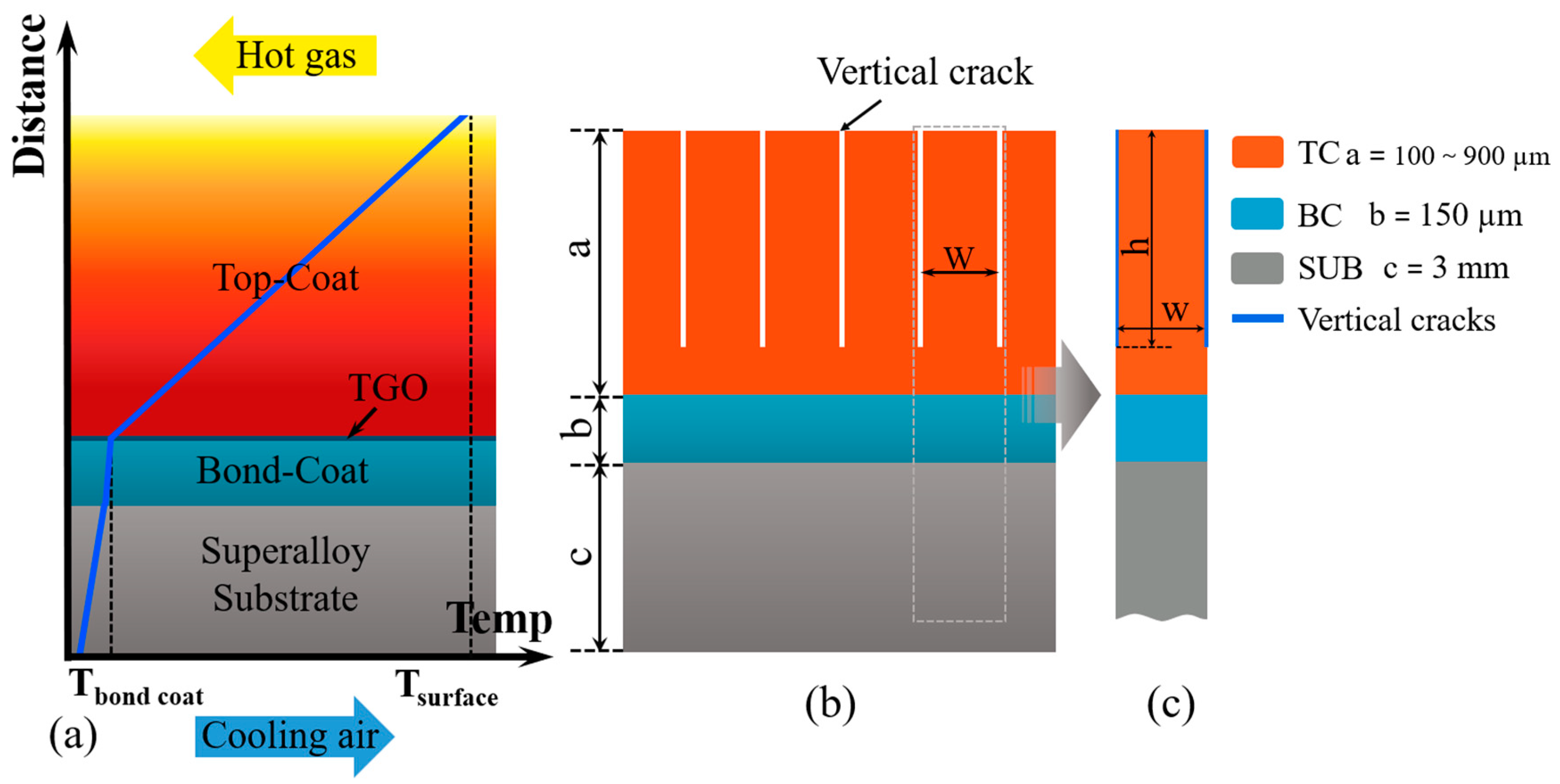
3.1. Description of the Finite Element Model Structure

The service environment of TBCs is complex and harsh. The complicated service environment is mainly summarized into three types: high-temperature gas thermal shock, foreign particle erosion, and calcium–magnesium–aluminum–silicate (CMAS) corrosion [38,39,40,41,42]. Among them, high-temperature gas thermal shock is inevitable during the service. It refers to the high-temperature and high-speed gas impact generated by the combustion of fuel in the engine on the surface of the TBCs, as shown in Figure 1a.
The TBCs were developed with three layers: TC layer, BC layer, and SUB layer. A two-dimensional plane strain model was developed based on the commercial FEM package ABAQUS. This simulation mainly focused on the understanding of stress evolution caused by sintering and thermal expansion mismatch. Therefore, a 2D simulation with an idealized interface geometry is advantageous due to its greater simplicity [43]. The entire geometry model used for finite element analysis is presented in Figure 1b. The a, b, and c are the thickness of the TC, BC, and SUB, respectively. Periodic vertical cracks were implanted in the TC layer to tailor the structure, which will be discussed later. The vertical crack starts from the coating surface and point to the BC interface. The h is the length of the vertical crack, and the w is the space between vertical cracks.
The present FEM is based on the following assumptions: (1) The SUB, BC, and TC on one side with pre-existing cracks are isotropic and homogeneous; (2) the geometric morphology at the TC/BC and BC/SUB interference is flat; and (3) the vertical cracks were only inserted into the TC.
The vertical cracks are distributed periodically in the model. A periodic unit can be extracted, which is symmetric about the central axis, as shown in Figure 1c. For the finite element simulation, half of the periodic unit can be used with proper boundary conditions to represent the whole unit. Therefore, a vertical crack and w/2 part are extracted from the entire unit for simulation, as shown in Figure 2a, and this representative region was also selected for the stress distribution diagram shown in the subsequent discussion of the results. At the root of the vertical crack, the first two nodes along the horizontal were separated, thereby prefabricating a small horizontal crack to investigate the effect of the introduction of the vertical cracks on the horizontal cracking, as shown in Figure 2b.

3.2. Model Boundary Conditions

The ceramic TC layer was taken to be linear elastic materials, whereas the BC and SUB were taken to be elastic–plastic materials [44]. The material parameters of each layer used for modeling are shown in Table 2.
In many coating systems, coating failure is driven by stresses caused by TGO growth and CTE mismatch between coating and substrate [43,45]. At initial thermal exposure, the TGO is relatively thin, whereas the sintering is more significant [29]. The stress will be mainly governed by the CTE mismatch stress, which will be affected by sintering [43,46]. During engine operation, thermal mismatch strain occurs due to the different thermal expansion coefficients of each layer, as shown in Equation (1). The strain direction is perpendicular to the coating surface. To investigate the evolution of stress and cracking driving force in the vertically cracked structure under high temperature induced by sintering and thermal mismatch strain, this model adopts the static model at room temperature with additional mechanical loading to model the real effect caused by temperature change. To simulate the mismatch strain between coating and substrate, a uniform strain of 0.2% was applied to the left boundary of the element model. The specific value was obtained according to Equation (1) of the coefficients of thermal expansion of the coating and the substrate. Simultaneously, a symmetry constraint is introduced on the right boundary under the pre-existing vertical crack. Moreover, the movement of bottom boundary at y-axis is fixed, which can prevent the occurrence of a rigid body displacement, as shown in Figure 2a. Many micro-scale cracks and pores are contained in the ceramic layer of conventional APS-TBC. During sintering at high temperatures, microscale cracks and pores were healed. The TBCs from the initial state to the sintered state mainly leads to the increase in the elastic modulus [17,29]. To focus on the effects of sintering and vertical cracks on the horizontal cracking of coatings, the mechanical properties related to conventional APS-TBC under thermal exposure were input into the region between vertical cracks to simulate the sintering of coatings. Therefore, the input range of the elastic modulus was set to 5–80% of the bulk YSZ material. Mesh refinement is executed near the interface and crack region because of our greater interest in these regions. The refined mesh is vividly demonstrated in Figure 2b. The mesh grid is dense enough that the strain energy release rate (SERR) at the crack tip will not be affected by mesh size.
ε = ( α 1 α 2 ) Δ T
where ε corresponds to the simulated thermal mismatch strain, and α1 and α2 are the coefficients of thermal expansion of SUB and TC. In this study, α1 is 13 × 10−6 /K, and α2 is 11 × 10−6 /K [18,47,48]. ΔT is the temperature change during cycling, which is 1000 K.
Figure 2. Model development: (a) finite element mesh and boundary conditions, (b) local cracking enlargement, (c) schematic of the VCCT for four node elements [49].
Coatings 12 01083 g002

3.3. Modeling Tool Used for Crack Propagation

The driving force for extension of the vertical crack is evaluated by SERR. The SERR is determined based on the virtual crack closure technique (VCCT), as shown in Figure 2c [49,50]. The VCCT mainly deals with cases based on linear elastic fracture mechanics. To focus on the effect of stiffening degree on SERR, no crack extension occurs in this study. In a four-node element, the SERR components Gi (i = I, II) can be obtained using the nodal force at the crack tip and the nodal opening displacement behind the crack tip. The total SERR G is the sum of the SERR components, as shown in the following equations [51]:
G Ι = F y Δ ν 2 B Δ α = F y ( ν 3 ν 4 ) 2 B Δ α
G Ι Ι = F x Δ μ 2 B Δ α = F x ( μ 3 μ 4 ) 2 B Δ α
G = G Ι + G Ι Ι ,
where Δα refers to the crack growth increment, Fx and Fy correspond to the shearing and opening force, respectively, and μi and νi are the shearing and opening displacement of the nodes behind the crack tip along the x- and y-axes, respectively. The parameter B is the thickness in the third direction, which is generally equal to 1 for the two-dimensional model with unit thickness.

4. Results and Discussion

4.1. Sintering-Induced Stiffening of Coatings

TBCs provide high thermal insulation to the metallic substrates to prolong the service life and thermal cycles without failure [5]. The TC of PS-TBCs has a lamellar porous structure, including microcracks, voids, and splat interfaces. Figure 3 shows the lamellar porous structure of plasma-sprayed TC before and after thermal exposure. Initially, the structure shows a lamellar stacking feature. There is only limited bonding between layers, resulting in the formation of unbounded interfaces or intersplat pores, as shown in Figure 3a. Some microcracks running through the thickness of individual layers are also observed. Intersplat pores and microcracks are also called 2D pores due to their very high aspect ratio. These 2D pores, as well as 3D globular voids, endow PS-TBCs with high performance. Their thermal conductivity and elastic modulus are less than 50% compared with those of the corresponding bulk materials [17,19,20,21]. The lamellar porous structure can effectively prevent heat flux, resulting in the required temperature drop with a certain thickness. In addition, it enhances strain tolerance, thereby reducing thermal stress during thermal cycling. After thermal exposure at 1000 °C for 20 h, changes in microstructure were observed, with the surface of 2D pores becoming rough and small pores healing. Larger cracks and 3D globular voids remain present, as shown in Figure 3b. At higher temperatures (at 1400 °C), the roughening of the surface becomes much more severe. Thus, sintering-induced healing of 2D pores is more significant, and the coating becomes denser, as revealed by the cross-sectional image (Figure 3c). Microstructural changes resulting from sintering change the mechanical properties of the coating.
Figure 4 shows the changes in the macroscopic and microscopic elastic moduli of TC before and after thermal exposure. The macroscopic elastic modulus is significantly lower than the microscopic modulus, indicating that the strain tolerance of the macrostructure is relatively high, which is consistent with previous reports [17,52,53]. This is attributed to the presence of large-scale pores in TC. After thermal exposure, the macroscopic and microscopic elastic moduli significantly increased. After 20 h exposure, the macroscopic elastic moduli increased sharply by approximately 83% and 215% after heat treatment at 1000 °C and 1400 °C, respectively. Afterward, the increase rate was significantly reduced. This is because several 2D pores were healed, and the residual wide pores and cracks have a slower healing rate. After 20 h exposure, the microscopic elastic moduli increased sharply by approximately 68% and 157% after heat treatment at 1000 °C and 1400 °C, respectively. This is because the elastic modulus of coatings is scale-sensitive. The macroscopic modulus of elasticity is influenced by the variation in pores in the structure during thermal exposure making it vary to a greater extent, which provides us with ideas for tailoring the macroscopic structure, which are discussed later. Figure 5 shows the evolution of the strain tolerance with thermal exposure time (normalized strain tolerance at different temperatures obtained here and in previous studies). A large drop (over 50%) in strain tolerance was observed after heat exposure. Moreover, exposure to higher temperatures resulted in faster and larger degradation. After 100 h of exposure, the strain tolerance of the samples exposed at 1000 °C and 1400 °C reduced by 50% and 78%, respectively. The durability of TBCs is largely affected by the strain and damage tolerance [54,55]. Because strain tolerance can relieve the stress induced by thermal expansion mismatch and other factors, sintering-induced degradation in strain tolerance is the main cause of TBC failure.

4.2. Stiffening Mechanism of Coatings

Porosity is commonly used to characterize structural changes in ceramic materials during sintering. Figure 6 shows the changes in the porosity and 2D pore density of the coatings under thermal exposure. Both porosity and 2D pore density were reduced throughout the sintering process. However, the variation degree of the 2D pore density is higher than that of the porosity (Figure 6c). After 100 h exposure at 1000 and 1400 °C, the porosity density decreased by 12% and 35%, and the 2D pore density decreased by 42% and 65%, respectively. In the first 20 h of thermal exposure, numerous 2D pores heal, resulting in a rapidly decreasing 2D pore density. Thereafter, the 2D pore density decreased by 36% and 52%, and the strain tolerance decreased by 46% and 68% for the samples exposed at 1000 °C and 1400 °C, respectively. However, the subsequent decrease rate decreased significantly, which was due to the slower healing process of the large pores. The changing trend is similar to the that of the mechanical properties, indicating that for PS-TBCs, the healing of 2D pores is the main cause of structural change during sintering, which account for the change in mechanical properties.
Figure 7 shows the morphological changes in the counter surfaces of an intersplat pore during thermal exposure [59]. After 10 h thermal exposure, the smooth counter surfaces of the intersplat pores gradually became wrinkled, forming a rough localized counter surface of the pores. Figure 8 shows AFM images of the coatings, showing the fluctuation of the surfaces. After thermal exposure, the surface within the grains became rough. Higher exposure temperatures resulted in more roughening, and the variation in hills and valleys in height increased [59]. For example, when the exposure temperature was increased from 1000 to 1400 °C, the peak wavelength increased from 25 to 95 nm. Figure 9 shows the TEM images of the coatings, revealing the change in pore surface bulge after thermal exposure. The surface became rough, which is consistent with Figure 7 and Figure 8. In summary, the smooth surface of a splat becomes rough under thermal exposure. This is attributed to grain boundary grooving and surface faceting. The grain boundary grooving is driven by the decrease in grain boundary energy, where the faceting is attributed to the anisotropy of the specific surface-free energy of different crystalline planes [60]. The rough undulations lead to multipoint bridging between the counter surfaces of intersplat pores, facilitating matter transport and decreasing the free energy of the whole system. The higher the temperature, the more rapid this process, thereby resulting in pore healing.
Under thermal exposure, the multiscale undulation of the originally smooth 2D pore inner surface triggers multipoint contact between the upper and lower inner surfaces, resulting in healing. The upper and lower inner surfaces of narrower 2D pores are closer, so multi-point contact is easier, leading to rapid healing. Therefore, the healing of 2D pores is the main cause of structural change in TBCs under thermal exposure and the main reason for the decrease in strain tolerance.

4.3. Failure Mechanism of TBCs

Research and industrial experience have revealed various conditions that cause structural deformation and performance degradation in TBCs. Damage in TBCs mostly results from external mechanical damage and compaction, thermal expansion mismatch, sintering, calcium–magnesium–alumina–silicate (CMAS)- and environment-induced erosion, corrosion, and oxidation [61]. Thermal expansion mismatch and sintering significantly affect the life span of TBC since they are the driving forces of cracking [62]. Thermal expansion mismatch is the additional stress in the coating due to the mismatch in the sintering rate and thermal expansion coefficient of the coating and substrate at high temperatures. Sintering changes the microstructure of coatings. Several 2D pores are healed, thereby increasing the elastic modulus and decreasing the strain compliance of the coating [63,64], and reducing stress concentration around the pore. However, residual wide pores and cracks can expand due to stress drive, which can cause the failure of TBCs [65,66]. Shinozaki et al. [57] reported the effect of sintering-induced stiffening in promoting the spallation of plasma-sprayed yttria-stabilized zirconia thermal barrier coatings. This suggests that the key degenerative process of TBCs is the stiffening of the coating due to the sintering phenomena at elevated temperatures. The increase in stiffness increases the strain-energy release rate for a given misfit strain, thereby accelerating coating failure. Guo et al. [67] investigated the effect of sintering on the thermal conductivity of TBCs. The result indicates that pores and microcracks are fewer and smaller after heat treatment, thereby compacting the ceramic layer. Moreover, the changes in the coating structure due to the sintering effect are irreversible, which remarkably increases the thermal conductivity. Densification also decreases the volume fraction of porosity, which in turn increases the thermal conductivity [68], meaning that the thermal insulation is significantly reduced, which accelerates the failure of the coating.

4.4. Effect of Thickness and Stiffness on Cracks

Based on the above experiments, sintering affects the strain tolerance and thermal insulation of the TBCs. Therefore, it is necessary to develop sintering-resistant TBC structures. To obtain better thermal insulation of the coating, material selection, porosity control, and other important parameters are needed, but the most intuitive technique is to increase the thickness of the coating. However, TBCs should exhibit not only high-level insulation but also good stress relaxation ability and high bond strength, which are also affected by the coating thickness [45]. Therefore, herein, we contrast the influence of the two aspects by simulations to develop sintering-resistant TBCs.

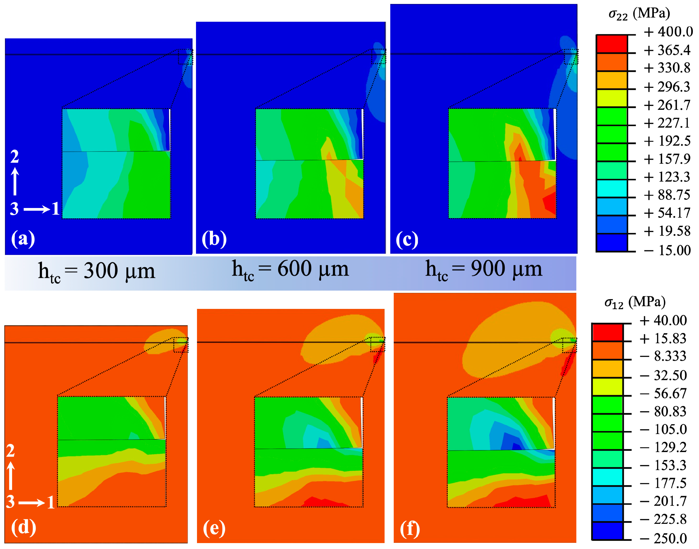
4.4.1. Influence of TC Thickness

The model shown in Figure 2 was developed by finite element software. The thickness of TC was varied to investigate its effects on the stress and SERR at the crack tip. Figure 10 shows the effect of TC thickness on the stress at the crack tips. With an increase in TC thickness, the stress at the crack tip was significantly increased. In addition, Figure 11a shows the effect of TC thickness on SERR at the crack tip. SERR for cracking on a 900 μm thick TC is approximately 2.7 times compared with that of 300 μm thick TC. The simulation results show that the driving force of cracking increases with an increase in TC thickness.
Related investigations on the influence of TC thickness on TBC life were collected, and the experimental data were normalized [57,69,70,71], as shown in Figure 11b. Generally speaking, the life of TBC decreases with an increase in TC thickness. Li et al. [71] studied and designed TBCs with both high thermal insulation and long lifetimes. The experimental results show that when the TC thickness is reduced from 0.5 to 0.4 mm, the life span of the TBC can be extended by 31%. Zhao et al. [70] investigated the structure and performance of 8YSZ TBCs with different thicknesses. The results showed that the service life was increased by 4.7 times when the TC thickness was reduced from 1 to 0.5 mm. Similarly, Shinozaki et al. [57] investigated the effect of sintering-induced stiffening in accelerating the spallation of plasma-sprayed YSZ TBCs. The spallation results obtained under 1500 °C showed that the thickness of TC changed from 0.3 to 0.7 mm, and the life span reduced by 77%. Based on the YSZ coating prepared through APS by Cheng et al. [72], the number of cycles in 1150/940 °C thermal gradient cycle tests exceeded 4000 when the thickness of TC was 0.57 mm, whereas the number of thermal cycles was only 203 when the thickness of TC was increased to 1 mm. Thus, the experimental data suggested that thicker coatings show a distinct tendency to spall more quickly. Some investigations have shown that thinner coatings have a short life span. This may be caused by the rapid reaction of the BC with oxygen that diffuses or penetrates the porous, thin TC [73]. In general, a larger TC thickness can improve the thermal insulation performance, but accelerate the failure of coatings. Therefore, under thermal insulation, an optimized TC thickness can effectively extend the life of TBCs.

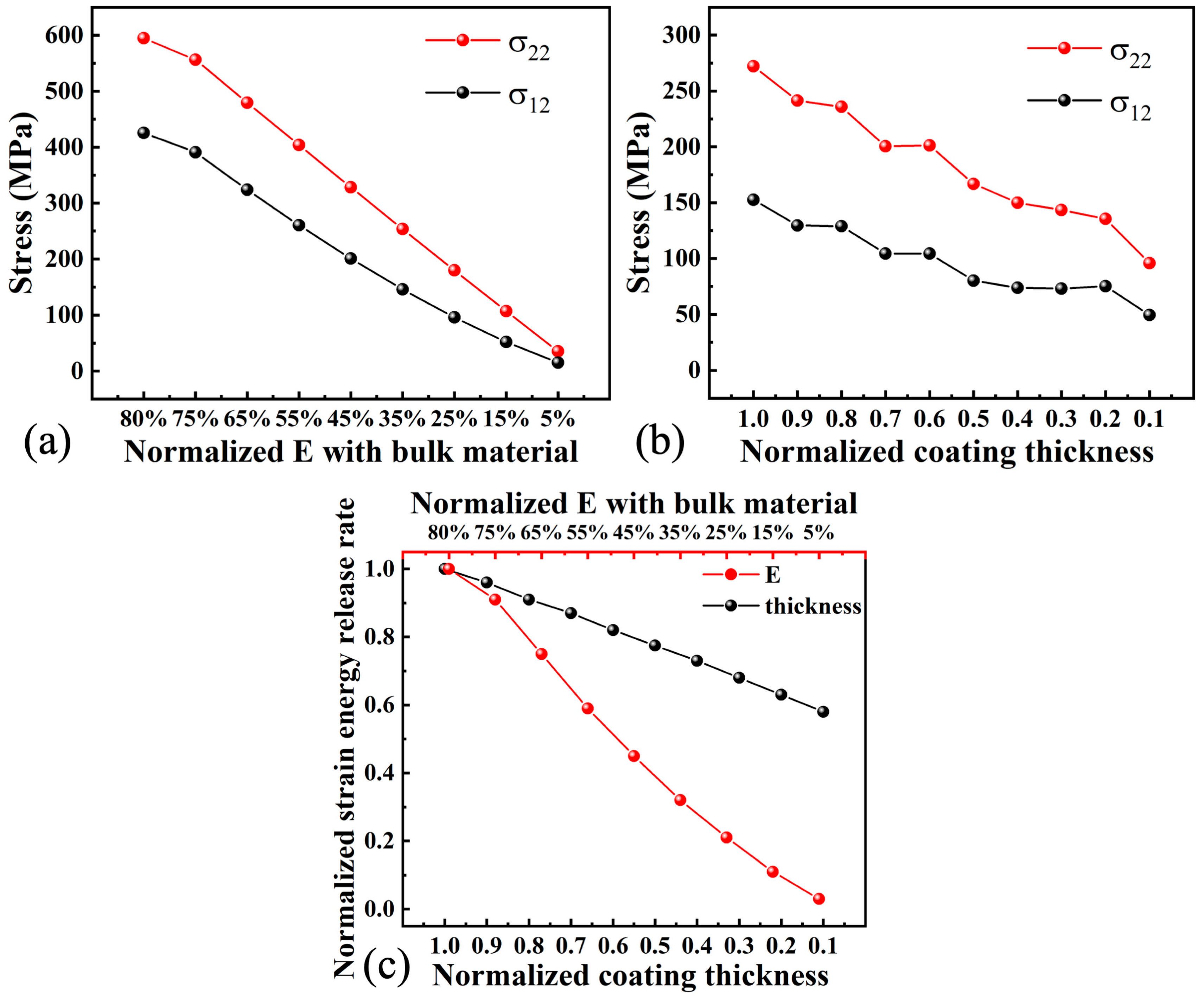
4.4.2. Influence of Elastic Modulus on SERR

To simulate TBC sintering under thermal exposure, the elastic modulus was used as input data. The variation range of the elastic modulus indicates the change from the sprayed state to the sintering state. For a more comprehensive study, the variation range of the elastic modulus of the selected area is larger than that of the experiment [29,56], which is 5–80% of that of the corresponding bulk YSZ material. Figure 12 shows the change in stress at crack tips under different elastic moduli. As the stiffening degree increases, stress at the crack tips increases significantly. When the elastic modulus of TC increases from 25% to 55% of that of the bulk material, SERR increases by 2.8 times. Cheng et al. [46] reported that the elastic modulus of a coating near the surface under different temperature-gradient thermal cycling increases from 60 to 90 GPa after failure (Figure 13). Zhong et al. [74] studied the effect of CeO2 content on the performance of TBCs and reported TBCs with different elastic moduli. The results suggest that an increase in the elastic modulus affects the life of TBCs. Chen et al. [75] studied the life and CMAS corrosion of nano-8YSZ TBCs and reported that as the elastic modulus of the coating increased from 29.2 to 54.6 Gpa, the life span of the TBC decreased from 103 to 70 thermal cycles; thus, they proposed that the elastic modulus of coatings is inversely related to their life span. Zhao et al. [76] observed that under the interaction of interfacial cracks, the length of surface cracks increases with an increase in the elastic modulus of TC (Figure 13).
When TBCs are exposed to high temperatures, the TC is sintered. The microcracks heal, and the porosity of TC decreases due to the sintering, increase in hardness, elastic modulus, and fracture toughness [77,78]. The elastic modulus of TC mainly affects surface cracks. As the elastic modulus increases, the surface cracks propagate and get closer to the interface, intensifying the influence of surface cracks on interfacial cracks and accelerating the failure of the coating [76]. In addition, Hui et al. [79] investigated the influence of material parameters on the energy release rate of interfacial cracks in TBCs using the extended finite element method. The results show that the energy release rate at TC/TGO and TGO/BC interfaces increases with an increase in the elastic modulus of TC. Zhou et al. [80] reported that the thermal cycling lifetime, mechanical properties, and microstructure of coatings can be correlated based on the following equation:
t f c ( K I C Y Δ ε E c ) n
where tf is the thermal cycling lifetime of the coatings, KIC is the fracture toughness of the coating, c is the initial defect size, Y is a geometry factor for initial defects, E is the elastic modulus, and Δε is the strain in the coating under thermal cycling. The exponent n is a material constant, which depends on the nature of the material. For ceramic materials, n is much greater than 1 [81]. Thus, an increase in the elastic modulus affects the life span of TBCs.

4.5. Structural Design of TBCs to Resist Sintering-Induced Stiffening

4.5.1. Dominant Factors Affecting the Life Span of TBCs

Based on the results obtained herein, the life span of TBCs is mainly affected by the thickness and elastic modulus of TC. As shown in Figure 14a,b, the simulation results show the effects of thickness and elastic modulus (stiffening degree) of TC on the stress at crack tips. A decrease in both thickness and elastic modulus of TC improves the life span of the coating. Figure 14c shows the normalized SERR as a function of thickness and elastic modulus. The elastic modulus has a more significant effect. Furthermore, effective thermal insulation requires a certain thickness of TC, which is often greater than 0.3 mm, to achieve a temperature drop of more than 50 °C. Therefore, reducing the elastic modulus of TC—that is, reducing the stiffening of TC—effectively increases the life span of TBCs.

4.5.2. Vertically Cracked Structure at Low SERR

An increase in the elastic modulus of TC is mainly caused by the healing of pores and microcracks in the coating due to sintering. Herein, a method for implanting vertical cracks into conventional lamellar TCs is proposed, and we investigate the effect of vertical crack density on lifetime and explore the potential mechanism of vertically cracked structure to enhance coating lifetime.
SERR, which determines the spallation lifetime of TBCs when reaching or being over the critical strain energy release rate (Gic), is directly proportional to the in-plane modulus of TC under a given strain [57]. Therefore, we explored the effect of scale-sensitive stiffening on the stress distribution and SERR at crack tips in TBCs with a vertically cracked structure and multiscale pores.
Figure 15a,b shows the stress distribution of 0.3 and 0.6 mm thick TC models after sintering. The maximum tensile and shear stresses are distributed at the tip of the prefabricated cracks. With a decrease in w/h, the peak stresses decrease. Figure 15c,d shows the effect of the vertically cracked structure on SERR. With TC thickness of 0.3 and 0.6 mm, when w/h decreases from 10 to 0.5, SERR decreases by 89.5% and 88.8%, respectively. A continuous decrease in stress and SERR reduces the probability of crack propagation.

4.5.3. Scale-Sensitive Stiffening for the Long Life Span of TBCs

TBCs with vertically cracked structures exhibit scale-sensitive stiffening behavior, as shown in Figure 16a,b. For a model with w/h = 20, the gap between two neighboring vertical cracks is very large, which is similar to the case of no vertical cracks [82]. Given that, the macroscopic and microscopic elastic moduli of TC are equal. With an increase in vertical cracks (or decrease in w/h), the increment of the macroscopic elastic modulus gradually becomes smaller than the microscopic elastic modulus. For a 0.3 mm thick TC, the microscopic elastic modulus increased from 10 to 160 GPa. When w/h = 10, the macroscopic elastic modulus increased from 7.02 to 112.37 GPa. In contrast, when w/h = 0.5, the macroscopic elastic modulus only increased from 1.21 to 19.42 GPa. Similarly, for a 0.6 mm thick TC, the microscopic elastic modulus increased by 150 GPa. When w/h = 10, the macroscopic elastic modulus increased from 7.99 to 127.95 GPa. However, when w/h = 0.5, the macroscopic elastic modulus only increased from 1.56 to 24.9 GPa. Figure 16c,d shows the normalized microscopic and macroscopic elastic moduli relative to the case where the microscopic elastic modulus is 40 GPa (w/h = 20). When the thickness of TC is 0.3 mm, with an increase in vertical cracks (a decrease in w/h), the microscopic elastic modulus is almost unchanged because the microstructure of TC remains unchanged. When the number of vertical cracks in TC increases to 39 (w/h = 0.5), the macroscopic elastic modulus is reduced by 87.9% compared to that of the case with no vertical cracks (w/h = 20), as shown in Figure 16c. To prevent the TC thickness from affecting this process, the case of the 0.6 mm thick TC is shown in Figure 16d. As w/h decreases, the microscopic elastic modulus remains unchanged. The macroscopic elastic modulus at w/h = 0.5 is 84.4% lower than that when w/h = 20. Based on Figure 16, even though the microscopic elastic modulus of TC is increased by sintering, the macroscopic elastic modulus increases slightly because the global stiffening effect is significantly reduced. With an increase in the number of vertical cracks, the stiffening effect is more significantly reduced. Thus, the strain tolerance of the TC layer is significantly enhanced due to the vertically cracked structure.
Multiscale pores can prevent macroscopic stiffening in TBCs, resulting in much lower SERR for cracking. Herein, the sintering-resistant design is analyzed. The macroscopic elastic modulus of the vertically cracked structure was used as input data for the simulation, which is equivalent to models with vertically cracked structures. In this way, the sintering-resistant effect of the TBC model after inducing vertical cracks could be obtained. As shown in Figure 17, the peak tensile and shear stresses at the crack tip of TC with different thicknesses decrease. When w/h decreases from 10 to 0.5, SERR of the 0.3, 0.6, and 0.9 mm thick TCs decreases by 79.9% (Figure 18a), 83.8% (Figure 18b), and 84.1% (Figure 18c), respectively. This result is consistent with that obtained in the previous section. Therefore, the implantation of vertical cracks can reduce the overall stiffening of TBCs, increase its strain tolerance, reduce the driving force for cracks, and extend the life span of TBCs.

5. Outlook

Traditional plasma-sprayed ceramic TC layers have a lamellar structure with no vertical cracks (Figure 19a). The strain tolerance is fair due to the numerous intersplat pores and intrasplat cracks. However, after thermal exposure, the micropores are healed, densifying the coating. Thus, both the micro- and macroscopic elastic moduli are greatly increased, and the strain tolerance is sharply reduced. This is a major reason coatings crack or spall easier after thermal service. The implantation of vertical cracks is an effective way to extend the life span of coatings (Figure 19b). In previous reports, vertical cracks were induced in columnar structured TBCs, such as columnar crystal structures prepared by EB-PVD [35,83,84,85] and dense vertically cracked TBC structures prepared by APS under high substrate temperatures [34,86,87]. They all contain vertical pores or cracks and have a longer life span than conventional APS coatings. Given the above results, the macroscopic elastic modulus of vertically cracked structures increases slightly, thus greatly reducing the sintering effect. Consequently, the strain tolerance can be enhanced, and its degradation during thermal exposure can be prevented to a large degree. However, the abovementioned two kinds of coatings have relatively dense structures in the out-plane direction, which increase the thermal conductivity of the coating. Consequently, the thermal insulation of the coatings is reduced. Therefore, TBCs with multiscale pores are highly required: the macroscopic vertical cracks enhance the strain tolerance, and the microscopic intersplat pores and cracks prevent heat flux. However, it is relatively difficult to achieve such a structure by the conventional plasma spraying method. There is a need to develop methods for implanting vertical cracks in plasma-sprayed coatings with high thermal insulation. In the simulation performed herein, the stress generated by TGO growth and the actual interfacial roughness were not considered. The pore structure, in reality, is more complicated than in the model: the orientation of the pore structure of the model has a certain degree of randomness. Therefore, for future studies, it is necessary to perform stress simulations that produce a more realistic state by controlling temperature changes.

6. Conclusions

In this study, the main effects of sintering on the failure of conventional plasma-sprayed coatings were investigated. The main reasons for the failure of TC of TBCs were discussed, and its influence on TBCs was analyzed by simulation. Furthermore, the structure was tailored and optimized to resist the sintering effect. In addition, the mechanism responsible for the increased life span was discussed. The main conclusions are as follows:
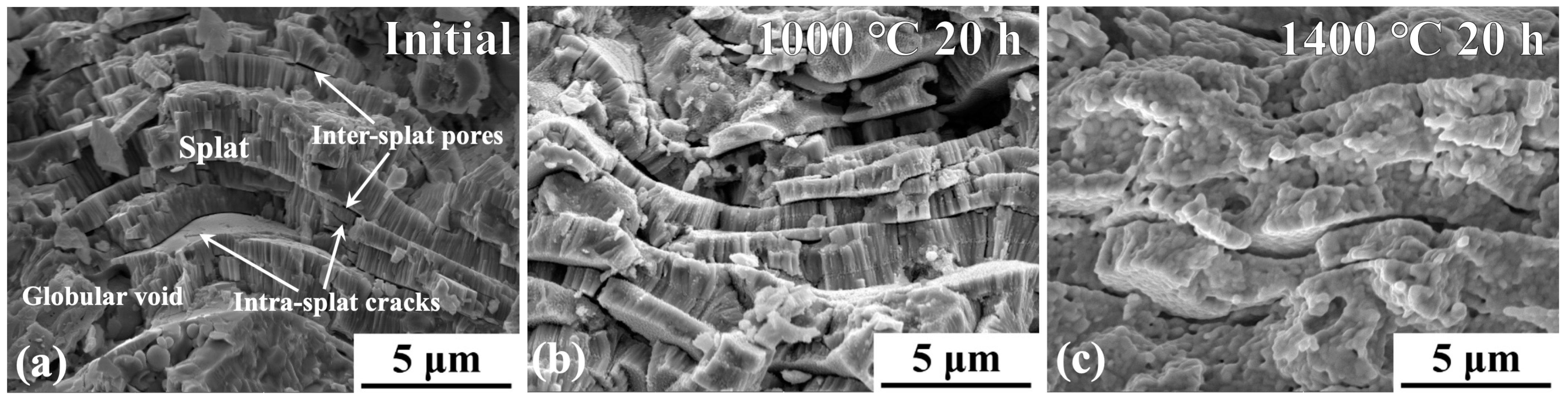
  • Under thermal exposure, multiscale undulations of the otherwise smooth 2D pore inner surface trigger multipoint contact between the upper and lower inner surfaces, resulting in pore healing. The healing of the 2D pores is the main structural change in PS-TBCs after thermal exposure and the main reason for the decrease in strain tolerance.
  • Based on simulations, the thickness and elastic modulus of coatings are the main factors affecting the cracking of TBCs. Moreover, sintering significantly increases the elastic modulus, which enlarges the driving force for crack propagation and causes the coating to fail. Effective thermal insulation requires a certain minimum thickness. Therefore, reducing the effect of sintering on stiffening would be an effective way to extend the life span of TBCs.
  • TBCs with vertical cracks can effectively resist the effect of sintering on global stiffening. In conventional coatings, the macroscopic and microscopic elastic moduli increase significantly during sintering. By inserting vertical cracks in coatings, the macroscopic elastic modulus is slightly increased, whereas the increase in microscopic elastic modulus is comparable to that in conventional coatings.
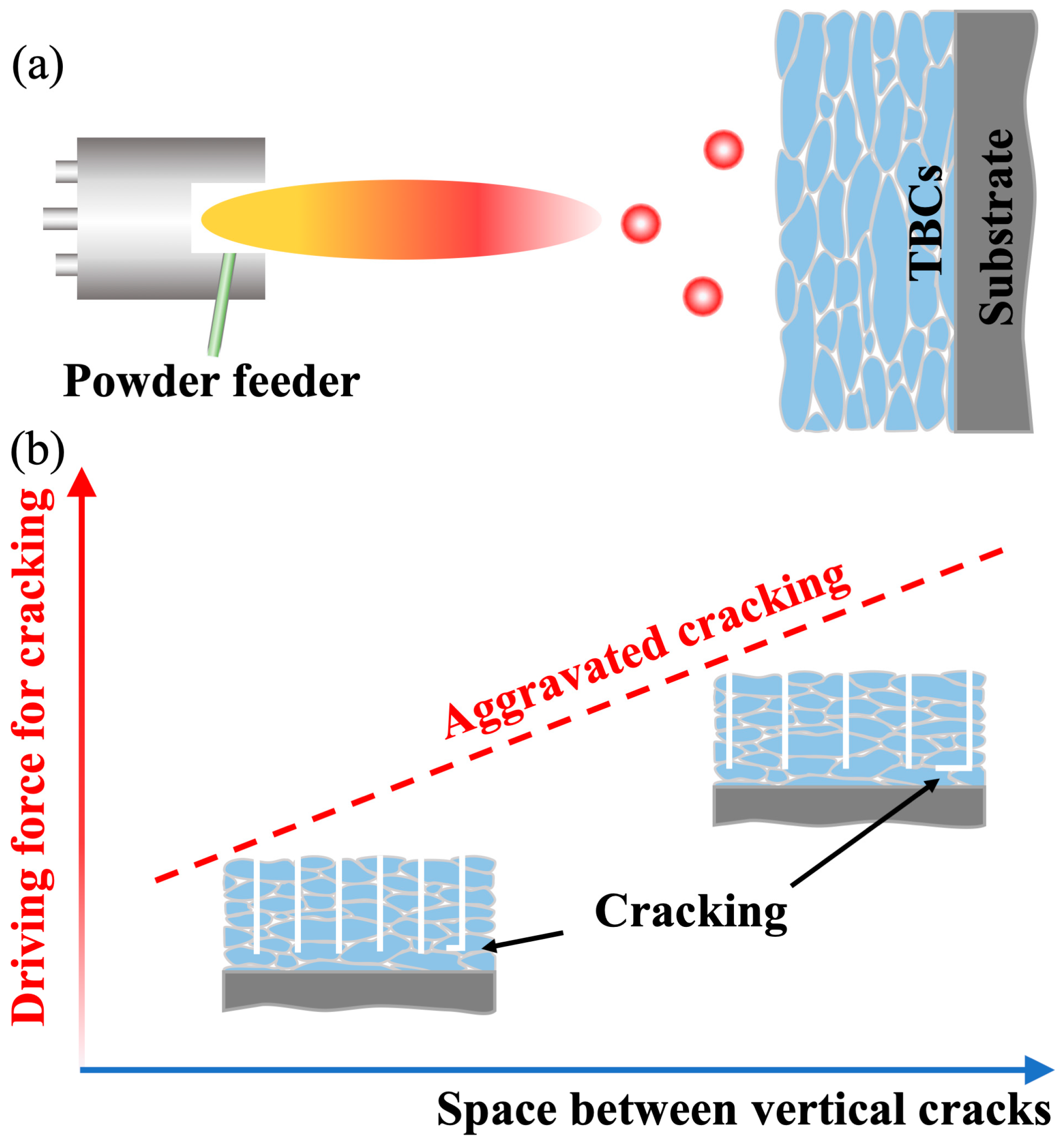
  • Vertically cracked structures extend the life span of coatings as the scale-sensitive stiffening decreases the driving force for cracking. The low global stiffening indicates a small strain-energy release rate, which determines the cracking of coatings. The simulation results show that the sintering effect and driving force for cracking can be decreased by 87.9% and 79.9%, respectively, at 0.3 mm thick TC. The strain tolerance of coatings with vertical cracks is enhanced, and the decrease in strain tolerance is reduced to a large extent.

Author Contributions

Conceptualization, L.-S.W., J.-B.S., H.D., and J.-T.Y.; Data curation, L.-S.W. and J.-B.S.; Formal analysis, L.-S.W., J.-B.S., and H.D.; Investigation, J.-B.S.; Methodology, L.-S.W. and H.D.; Resources, L.-S.W. and J.-B.S.; Software, J.-B.S. and J.-T.Y.; Validation, H.D.; Visualization, H.D. and J.-T.Y.; Writing—original draft, L.-S.W. and J.-B.S.; Writing—review and editing, J.-T.Y. All authors have read and agreed to the published version of the manuscript.

Funding

This work was supported by the National Natural Science Foundation of China (grant number 51901181); the Natural Science Foundation of Shaanxi Province (grant number 2020JQ-771); the Young Talent fund of University Association for Science and Technology in Shaanxi, China (grant number 20200427); the Materials Science and Engineering of Provincial Advantage Disciplines, Xi’an Shiyou University (grant number YS37020203); the Key Laboratory of High Performance Oil and Gas Field Materials, School of Material Science and Engineering, Xi’an Shiyou University; and the postgraduate innovation and practical ability training program of Xi’an Shiyou University (grant number YCS20212126).

Institutional Review Board Statement

Not applicable.

Informed Consent Statement

Not applicable.

Data Availability Statement

The data presented in this study are available on request from the corresponding author after obtaining permission from the authorized individual.

Acknowledgments

The authors would like to thank Zhiyuan Wei for his assistance in in coating preparation and simulations.

Conflicts of Interest

The authors declare no conflict of interest.

References

  1. Padture, N.P.; Gell, M.; Jordan, E.H. Thermal barrier coatings for gas-turbine engine applications. Science 2002, 296, 280–284. [Google Scholar] [CrossRef] [PubMed]
  2. Padture, N.P. Advanced structural ceramics in aerospace propulsion. Nat. Mater. 2016, 15, 804–809. [Google Scholar] [CrossRef] [PubMed]
  3. Cao, X.Q.; Vassen, R.; Fischer, W.; Tietz, F.; Jungen, W.; Stoever, D. Lanthanum cerium oxide as thermal barrier coating material for high temperature applications. Adv. Mater. 2003, 15, 1438–1442. [Google Scholar] [CrossRef]
  4. Cao, X.Q.; Zhang, Y.F.; Zhang, J.F.; Zhong, X.H.; Wang, Y.; Ma, H.M.; Xu, Z.H.; He, L.M.; Lu, F. Failure of the plasma-sprayed coating of lanthanum hexaluminate. J. Eur. Ceram. Soc. 2008, 28, 1979–1986. [Google Scholar] [CrossRef]
  5. Clarke, D.R.; Oechsner, M.; Padture, N.P. Thermal-barrier coatings for more efficient gas-turbine engines. MRS Bull. 2012, 37, 891–898. [Google Scholar] [CrossRef] [Green Version]
  6. Schlichting, K.W.; Padture, N.P.; Jordan, E.H.; Gell, M. Failure modes in plasma-sprayed thermal barrier coatings. Mater. Sci. Eng. A 2003, 342, 120–130. [Google Scholar] [CrossRef]
  7. Chavez, J.; Naraparaju, R.; Mechnich, P.; Kelm, K.; Schulz, U.; Ramana, C.V. Effects of yttria content on the CMAS infiltration resistance of yttria stabilized thermal barrier coatings system. J. Mater. Sci. Technol. 2020, 43, 76–85. [Google Scholar] [CrossRef]
  8. Zhang, B.Y.; Meng, G.H.; Yang, G.J.; Li, C.X.; Li, C.J. Dependence of scale thickness on the breaking behavior of the initial oxide on plasma spray bond coat surface during vacuum pre-treatment. Appl. Surf. Sci. 2017, 397, 125–132. [Google Scholar] [CrossRef] [Green Version]
  9. Zhang, B.Y.; Yang, G.J.; Li, C.X.; Li, C.J. Non-parabolic isothermal oxidation kinetics of low pressure plasma sprayed MCrAlY bond coat. Appl. Surf. Sci. 2017, 406, 99–109. [Google Scholar] [CrossRef] [Green Version]
  10. Meng, G.H.; Liu, H.; Xu, P.Y.; Li, G.R.; Xu, T.; Yang, G.J.; Li, C.J. Superior oxidation resistant MCrAlY bond coats prepared by controlled atmosphere heat treatment. Corros. Sci. 2020, 170, 108653. [Google Scholar] [CrossRef]
  11. Meng, G.H.; Liu, H.; Liu, M.J.; Xu, T.; Yang, G.J.; Li, C.X.; Li, C.J. Large-grain α-Al2O3 enabling ultra-high oxidation-resistant MCrAlY bond coats by surface pre-agglomeration treatment. Corros. Sci. 2020, 163, 108275. [Google Scholar] [CrossRef]
  12. Meng, G.H.; Liu, H.; Liu, M.J.; Xu, T.; Yang, G.J.; Li, C.X.; Li, C.J. Highly oxidation resistant MCrAlY bond coats prepared by heat treatment under low oxygen content. Surf. Coat. Technol. 2019, 368, 192–201. [Google Scholar] [CrossRef]
  13. Wu, P.; Hu, M.Y.; Chong, X.Y.; Feng, J. The glass-like thermal conductivity in ZrO2-Dy3TaO7 ceramic for promising thermal barrier coating application. Appl. Phys. Lett. 2018, 112, 131903. [Google Scholar] [CrossRef]
  14. Swadźba, R. Interfacial phenomena and evolution of modified aluminide bondcoatings in thermal barrier coatings. Appl. Surf. Sci. 2018, 445, 133–144. [Google Scholar] [CrossRef]
  15. Herbert, H. Plasma-sprayed coatings. Sci. Am. 1988, 259, 837–844. [Google Scholar] [CrossRef]
  16. Bakan, E.; Mack, D.E.; Mauer, G.; Mücke, R.; Vaßen, R.; Troczynski, T. Porosity–property relationships of plasma-sprayed Gd2Zr2O7/YSZ thermal barrier coatings. J. Am. Ceram. Soc. 2015, 98, 2647–2654. [Google Scholar] [CrossRef]
  17. Paul, S.; Cipitria, A.; Tsipas, S.A.; Clyne, T.W. Sintering characteristics of plasma sprayed zirconia coatings containing different stabilisers. Surf. Coat. Technol. 2009, 203, 1069–1074. [Google Scholar] [CrossRef]
  18. Cipitria, A.; Golosnoy, I.O.; Clyne, T.W. A sintering model for plasma-sprayed zirconia TBCs. Part I: Free-standing coatings. Acta Mater. 2009, 57, 980–992. [Google Scholar] [CrossRef]
  19. Kulkarni, A.; Wang, Z.; Nakamura, T.; Sampath, S.; Goland, A.; Herman, H.; Allen, J.; Ilavsky, J.; Long, G.; Frahm, J.; et al. Comprehensive microstructural characterization and predictive property modeling of plasma-sprayed zirconia coatings. Acta Mater. 2003, 51, 2457–2475. [Google Scholar] [CrossRef]
  20. Tan, Y.; Longtin, J.P.; Sampath, S.; Wang, H. Effect of the starting microstructure on the thermal properties of as-sprayed and thermally exposed plasma-sprayed YSZ coatings. J. Am. Ceram. Soc. 2009, 92, 710–716. [Google Scholar] [CrossRef]
  21. Tan, Y.; Shyam, A.; Choi, W.B.; Lara-Curzio, E.; Sampath, S. Anisotropic elastic properties of thermal spray coatings determined via resonant ultrasound spectroscopy. Acta Mater. 2010, 58, 5305–5315. [Google Scholar] [CrossRef]
  22. Mahmoud Zaghloul, M.Y.; Yousry Zaghloul, M.M.; Yousry Zaghloul, M.M. Developments in polyester composite materials—An in-depth review on natural fibres and nano fillers. Compos. Struct. 2021, 278, 114698. [Google Scholar] [CrossRef]
  23. Fuseini, M.; Zaghloul, M.M.Y.; Elkady, M.F.; El-Shazly, A.H. Evaluation of synthesized polyaniline nanofibres as corrosion protection film coating on copper substrate by electrophoretic deposition. J. Mater. Sci. 2022, 57, 6085–6101. [Google Scholar] [CrossRef]
  24. Fuseini, M.; Zaghloul, M.M.Y. Statistical and qualitative analyses of the kinetic models using electrophoretic deposition of polyaniline. J. Ind. Eng. Chem. 2022, in press. [Google Scholar] [CrossRef]
  25. Eldridge, J.I.; Spuckler, C.M.; Markham, J.R. Determination of scattering and absorption coefficients for plasma-sprayed yttria-stabilized zirconia thermal barrier coatings at elevated temperatures. J. Am. Ceram. Soc. 2009, 92, 2276–2285. [Google Scholar] [CrossRef]
  26. Chen, W.R.; Wu, X.; Dudzinski, D. Influence of thermal cycle frequency on the TGO growth and cracking behaviors of an APS-TBC. J. Therm. Spray Technol. 2012, 21, 1294–1299. [Google Scholar] [CrossRef]
  27. Fang, X.; Zhang, G.; Feng, X. Performance of TBCs system due to the different thicknesses of top ceramic layer. Ceram. Int. 2015, 41, 2840–2846. [Google Scholar] [CrossRef]
  28. Zaghloul, M.Y.; Zaghloul, M.M.Y.; Zaghloul, M.M.Y. Influence of stress level and fibre volume fraction on fatigue performance of glass fibre-reinforced polyester composites. Polymers 2022, 14, 2662. [Google Scholar] [CrossRef]
  29. Li, G.R.; Xie, H.; Yang, G.J.; Liu, G.; Li, C.X.; Li, C.J. A comprehensive sintering mechanism for TBCs-Part I: An overall evolution with two-stage kinetics. J. Am. Ceram. Soc. 2017, 100, 2176–2189. [Google Scholar] [CrossRef]
  30. Choi, S.R.; Zhu, D.M.; Miller, R.A. Effect of sintering on mechanical properties of plasma-sprayed zirconia-based thermal barrier coatings. J. Am. Ceram. Soc. 2005, 88, 2859–2867. [Google Scholar] [CrossRef]
  31. Zhao, Y.; Gao, Y. Structural evolution of plasma-sprayed nanoscale 3 mol% and 5 mol% yttria-stabilized zirconia coatings during sintering. Appl. Surf. Sci. 2017, 425, 1033–1039. [Google Scholar] [CrossRef]
  32. Huan, Y.C.; Wu, K.D.; Li, C.J.; Liao, H.L.; Debliquy, M.; Zhang, C. Micro-nano structured functional coatings deposited by liquid plasma spraying. J. Adv. Ceram. 2020, 9, 517–534. [Google Scholar] [CrossRef]
  33. Guo, L.; Xin, H.; Zhang, Z.; Zhang, X.M.; Ye, F.X. Microstructure modification of Y2O3 stabilized ZrO2 thermal barrier coatings by laser glazing and the effects on the hot corrosion resistance. J. Adv. Ceram. 2020, 9, 232–242. [Google Scholar] [CrossRef] [Green Version]
  34. Karger, M.; Vaßen, R.; Stöver, D. Atmospheric plasma sprayed thermal barrier coatings with high segmentation crack densities: Spraying process, microstructure and thermal cycling behavior. Surf. Coat. Technol. 2011, 206, 16–23. [Google Scholar] [CrossRef]
  35. Schulz, U.; Saruhan, B.; Fritscher, K.; Leyens, C. Review on advanced EB-PVD ceramic topcoats for TBC applications. Int. J. Appl. Ceram. Technol. 2004, 1, 302–315. [Google Scholar] [CrossRef]
  36. Chi, W.; Sampath, S.; Wang, H. Microstructure–thermal conductivity relationships for plasma-sprayed yttria-stabilized zirconia coatings. J. Am. Ceram. Soc. 2008, 91, 2636–2645. [Google Scholar] [CrossRef]
  37. Liu, T.; Luo, X.T.; Chen, X.; Yang, G.J.; Li, C.X.; Li, C.J. Morphology and size evolution of interlamellar two-dimensional pores in plasma-sprayed La2Zr2O7 coatings during thermal exposure at 1300 °C. J. Therm. Spray Technol. 2015, 24, 739–748. [Google Scholar] [CrossRef]
  38. Zhou, Y.C.; Liu, Q.X.; Yang, L.; Wu, D.J.; Mao, W.G. Failure mechanisms and life prediction of thermal barrier coatings. CJSM 2010, 31, 504–531. [Google Scholar] [CrossRef]
  39. Sun, Y.N.; Xiang, H.M.; Dai, F.Z.; Wang, X.H.; Xing, Y.; Zhao, X.J.; Zhou, Y.C. Preparation and properties of CMAS resistant bixbyite structured high-entropy oxides RE2O3 (RE = Sm, Eu, Er, Lu, Y, and Yb): Promising environmental barrier coating materials for Al2O3f/Al2O3 composites. J. Adv. Ceram. 2021, 10, 596–613. [Google Scholar] [CrossRef]
  40. Guo, L.; Li, G.; Gan, Z.L. Effects of surface roughness on CMAS corrosion behavior for thermal barrier coating applications. J. Adv. Ceram. 2021, 10, 472–481. [Google Scholar] [CrossRef]
  41. Li, D.X.; Jiang, P.; Gao, R.H.; Sun, F.; Jin, X.C.; Fan, X.L. Experimental and numerical investigation on the thermal and mechanical behaviours of thermal barrier coatings exposed to CMAS corrosion. J. Adv. Ceram. 2021, 10, 551–564. [Google Scholar] [CrossRef]
  42. Liu, S.H.; Ji, G.; Li, C.J.; Li, C.X.; Guo, H.B. Novel long laminar plasma sprayed hybrid structure thermal barrier coatings for high-temperature anti-sintering and volcanic ash corrosion resistance. J. Mater. Sci. Technol. 2021, 79, 141–146. [Google Scholar] [CrossRef]
  43. Bäker, M.; Seiler, P. A guide to finite element simulations of thermal barrier coatings. J. Therm. Spray Technol. 2017, 26, 1146–1160. [Google Scholar] [CrossRef] [Green Version]
  44. Wang, L.; Zhong, X.H.; Shao, F.; Ni, J.X.; Yang, J.S.; Tao, S.Y.; Wang, Y. What is the suitable segmentation crack density for atmospheric plasma sprayed thick thermal barrier coatings with the improved thermal shock resistance? Appl. Surf. Sci. 2018, 431, 101–111. [Google Scholar] [CrossRef]
  45. Bäker, M.; Fiedler, T.; Rösler, J. Stress evolution in thermal barrier coatings for rocket engine applications. Mech. Adv. Mater. Mod. Process. 2015, 1, 5. [Google Scholar] [CrossRef] [Green Version]
  46. Cheng, B.; Zhang, Y.M.; Yang, N.; Zhang, M.; Chen, L.; Yang, G.J.; Li, C.X.; Li, C.J. Sintering-induced delamination of thermal barrier coatings by gradient thermal cyclic test. J. Am. Ceram. Soc. 2017, 100, 1820–1830. [Google Scholar] [CrossRef]
  47. Wang, C.J.; Wang, Y.; Zhang, Z.Q. Nano-Sized Thermal Barrier Coating Materials; Metallurgical Industry Press: Beijing, China, 2017; p. 191. [Google Scholar]
  48. Cipitria, A.; Golosnoy, I.O.; Clyne, T.W. A sintering model for plasma-sprayed zirconia thermal barrier coatings. Part II: Coatings bonded to a rigid substrate. Acta Mater. 2009, 57, 993–1003. [Google Scholar] [CrossRef] [Green Version]
  49. Wei, Z.Y.; Cheng, B.; Wang, J.; Liu, M.J.; Cai, H.N. Extend the thermal cyclic lifetime of La2Zr2O7/YSZ DCL TBCs by reducing modulus design on a toughening ceramic surface. Surf. Coat. Technol. 2019, 374, 134–143. [Google Scholar] [CrossRef]
  50. Shivakumar, K.N.; Tan, P.W.; Newman, J.C. A virtual crack-closure technique for calculating stress intensity factors for cracked three dimensional bodies. Int. J. Fract. 1988, 36, R43–R50. [Google Scholar] [CrossRef]
  51. Fan, X.L.; Jiang, W.; Li, J.G.; Suo, T.; Wang, T.J.; Xu, R. Numerical study on interfacial delamination of thermal barrier coatings with multiple separations. Surf. Coat. Technol. 2014, 244, 117–122. [Google Scholar] [CrossRef]
  52. Li, G.R.; Lv, B.W.; Yang, G.J.; Zhang, W.X.; Li, C.X.; Li, C.J. Relationship between lamellar structure and elastic modulus of thermally sprayed thermal barrier coatings with intra-splat cracks. J. Therm. Spray Technol. 2015, 24, 1355–1367. [Google Scholar] [CrossRef]
  53. Guo, S.Q.; Kagawa, Y. Young’s moduli of zirconia top-coat and thermally grown oxide in a plasma-sprayed thermal barrier coating system. Scripta Mater. 2004, 50, 1401–1406. [Google Scholar] [CrossRef]
  54. Zou, Z.; Xing, C.; He, L.; Shan, X.; Luo, L.; Zhao, X.; Guo, F.; Xiao, P. A highly strain and damage-tolerant thermal barrier coating fabricated by electro-sprayed zirconia hollow spheres. J. Am. Ceram. Soc. 2018, 101, 4375–4386. [Google Scholar] [CrossRef]
  55. Mehboob, G.; Liu, M.-J.; Xu, T.; Hussain, S.; Mehboob, G.; Tahir, A. A review on failure mechanism of thermal barrier coatings and strategies to extend their lifetime. Ceram. Int. 2020, 46, 8497–8521. [Google Scholar] [CrossRef]
  56. Li, G.R.; Yang, G.J.; Li, C.X.; Li, C.J. A comprehensive sintering mechanism for TBCs-Part III: Substrate constraint effect on healing of 2D pores. J. Am. Ceram. Soc. 2018, 101, 3636–3648. [Google Scholar] [CrossRef]
  57. Shinozaki, M.; Clyne, T.W. A methodology, based on sintering-induced stiffening, for prediction of the spallation lifetime of plasma-sprayed coatings. Acta Mater. 2013, 61, 579–588. [Google Scholar] [CrossRef]
  58. Zhu, J.; Ma, K. Microstructural and mechanical properties of thermal barrier coating at 1400 °C treatment. Theor. Appl. Mech. Lett. 2014, 4, 021008. [Google Scholar] [CrossRef] [Green Version]
  59. Wang, L.S.; Wei, Z.Y.; Cheng, B.; Liu, M.J.; Li, G.R.; Dong, H.; Yang, G.J. Gradient stiffening induced interfacial cracking and strain tolerant design in thermal barrier coatings. Ceram. Int. 2020, 46, 2355–2364. [Google Scholar] [CrossRef]
  60. Li, G.R.; Xie, H.; Yan, G.J.; Liu, G.; Li, C.X.; Li, C. A comprehensive sintering mechanism for TBCs-Part II: Multiscale multipoint interconnection-enhanced initial kinetics. J. Am. Ceram. Soc. 2017, 100, 4240–4251. [Google Scholar] [CrossRef]
  61. Mondal, K.; Nunẽz, L.; Iii, C.; Downey, I.; Van Rooyen, I. Thermal barrier coatings overview: Design, manufacturing, and applications in high-temperature industries. Ind. Eng. Chem. Res. 2021, 60, 6061–6077. [Google Scholar] [CrossRef]
  62. Li, G.R.; Tang, C.H.; Yang, G.J. Dynamic-stiffening-induced aggravated cracking behavior driven by metal-substrate-constraint in a coating/substrate system. J. Mater. Sci. Technol. 2021, 65, 154–163. [Google Scholar] [CrossRef]
  63. Markocsan, N.; Nylén, P.; Wigren, J.; Li, X.H.; Tricoire, A. Effect of thermal aging on microstructure and functional properties of zirconia-base thermal barrier coatings. J. Therm. Spray Technol. 2009, 18, 201–208. [Google Scholar] [CrossRef]
  64. Sun, F.; Fan, X.; Zhang, T.; Jiang, P.; Yang, J. Numerical analysis of the influence of pore microstructure on thermal conductivity and Young’s modulus of thermal barrier coating. Ceram. Int. 2020, 46, 24326–24332. [Google Scholar] [CrossRef]
  65. Bacciochini, A.; Ben Ettouil, F.; Brousse, E.; Ilavsky, J.; Montavon, G.; Denoirjean, A.; Valette, S.; Fauchais, P. Quantification of void networks of as-sprayed and annealed nanostructured yttria-stabilized zirconia (YSZ) deposits manufactured by suspension plasma spraying. Surf. Coat. Technol. 2010, 205, 683–689. [Google Scholar] [CrossRef]
  66. Yang, M.; Li, Z.G.; Wang, X.Y.; Li, Y.H.; Chen, F.; Li, M.; Chen, Y.; Chen, W. Effect of spraying ceramic powder pore structure on thermophysical properties of plasma-sprayed thermal barrier coatings. Ceram. Int. 2022, 48, 1125–1131. [Google Scholar] [CrossRef]
  67. Wang, K.; Peng, H.; Guo, H.B.; Gong, S.K. Effect of sintering on thermal conductivity and thermal barrier effects of thermal barrier coatings. Chin. J. Aeronaut. 2012, 25, 811–816. [Google Scholar] [CrossRef] [Green Version]
  68. Clarke, D.; Levi, C.G. Materials design for the next generation thermal barrier coatings. Annu. Rev. Mater. Res 2003, 33, 383–417. [Google Scholar] [CrossRef]
  69. Dai, H.; Zhong, X.; Li, J.; Zhang, Y.; Meng, J.; Cao, X. Thermal stability of double-ceramic-layer thermal barrier coatings with various coating thickness. Mater. Sci. Eng. A 2006, 433, 1–7. [Google Scholar] [CrossRef]
  70. Zhao, D.; An, Y.L.; Zhao, X.Q.; Liu, G.; Chen, J.; Zhou, H.D. Structure and properties of 8YSZ thermal barrier coatings with different thickness. Surf. Technol. 2020, 49, 9. [Google Scholar] [CrossRef]
  71. Li, G.R.; Wang, L.S. Durable TBCs with self-enhanced thermal insulation based on co-design on macro- and microstructure. Appl. Surf. Sci. 2019, 483, 472–480. [Google Scholar] [CrossRef]
  72. Cheng, B.; Yang, N.; Zhang, Q.; Zhang, M.; Zhang, Y.M.; Chen, L.; Yang, G.J.; Li, C.X.; Li, C.J. Sintering induced the failure behavior of dense vertically crack and lamellar structured TBCs with equivalent thermal insulation performance. Ceram. Int. 2017, 43, 15459–15465. [Google Scholar] [CrossRef]
  73. Choi, H.M.; Kang, B.S.; Choi, W.K.; Choi, D.G.; Choi, S.K.; Kim, J.C.; Park, Y.K.; Kim, G.M. Effect of the thickness of plasma-sprayed coating on bond strength and thermal fatigue characteristics. J. Mater. Sci. 1998, 33, 5895–5899. [Google Scholar] [CrossRef]
  74. Zhong, X.H.; Xu, Z.H.; Zhang, Y.F.; Zhang, J.F.; Chen, X.L.; Cao, X.Q. Influence of ceria content on performance of neodymium-cerium composite oxide thermal barrier coatings. JAM 2009, 29, 11–18. [Google Scholar]
  75. Chen, T.; Hui, Y.; Xu, J.Y.; Zhou, B.L.; Cao, X.Q.; Zhao, X.J. Effect of heat treatment of nano 8YSZ powder on thermal shock lifetime of plasma sprayed coating. JRE 2016, 34, 10. [Google Scholar] [CrossRef]
  76. Zhao, K.; Chen, Z.; Jia, W.B.; Huang, H.M.; Fang, L.; Zhou, B.Z. Interaction between surface crack and interface crack in thermal barrier coatings under thermal load. Aeroengine 2021, 47, 7. [Google Scholar] [CrossRef]
  77. Xiao, B.J.; Huang, X.; Robertson, T.; Tang, Z.; Kearsey, R. Sintering resistance of suspension plasma sprayed 7YSZ TBC under isothermal and cyclic oxidation. J. Eur. Ceram. Soc. 2020, 40, 2030–2041. [Google Scholar] [CrossRef]
  78. Zhou, D.P.; Malzbender, J.; Sohn, Y.J.; Guillon, O.; Vaßen, R. Sintering behavior of columnar thermal barrier coatings deposited by axial suspension plasma spraying (SPS). J. Eur. Ceram. Soc. 2019, 39, 482–490. [Google Scholar] [CrossRef]
  79. Hui, M.T.; Yu, Q.M.; Shi, Y.Z. Influence of material parameters on the interfacial crack growth in thermal barrier coating system. Ceram. Int. 2019, 45, 8414–8427. [Google Scholar] [CrossRef]
  80. Zhou, D.P.; Guillon, O.; Vaßen, R. Development of YSZ thermal barrier coatings using axial suspension plasma spraying. Coatings 2017, 7, 120. [Google Scholar] [CrossRef] [Green Version]
  81. Munz, D.; Fett, T. Ceramics: Mechanical properties, failure behaviour, materials selection. Ann. Chim. Sci. Mat. 1999, 25, 75. [Google Scholar] [CrossRef]
  82. Mehboob, G.; Xu, T.; Li, G.R.; Yang, G.J.; Tahir, A.; Ragab, M.; Hussain, S. Tailoring periodic vertical cracks in thermal barrier coatings enabling high strain tolerance. Coatings 2021, 11, 720. [Google Scholar] [CrossRef]
  83. Steinbrech, R.W.; Postolenko, V.; Mönch, J.; Malzbender, J.; Singheiser, L. Testing method to assess lifetime of EB-PVD thermal barrier coatings on tubular specimens in static and cyclic oxidation tests. Ceram. Int. 2011, 37, 363–368. [Google Scholar] [CrossRef]
  84. Guo, S.; Kagawa, Y. Isothermal and cycle properties of EB-PVD yttria-partially-stabilized zirconia thermal barrier coatings at 1150 and 1300 °C. Ceram. Int. 2007, 33, 373–378. [Google Scholar] [CrossRef]
  85. Guo, S.; Kagawa, Y. Effect of thermal exposure on hardness and Young’s modulus of EB-PVD yttria-partially-stabilized zirconia thermal barrier coatings. Ceram. Int. 2006, 32, 263–270. [Google Scholar] [CrossRef]
  86. Guo, H.B.; Vaßen, R.; Stöver, D. Thermophysical properties and thermal cycling behavior of plasma sprayed thick thermal barrier coatings. Surf. Coat. Technol. 2005, 192, 48–56. [Google Scholar] [CrossRef]
  87. Gray, D.M.; Lau, Y.C.; Johnson, C.A.; Borom, M.P.; Nelson, W.A. Thermal Barrier Coatings Having an Improved Columnar Microstructure. U.S. Patent 08/681558, 11 March 1998. [Google Scholar]
Figure 1. Schematic diagram of model structure: (a) TBC service environment during thermal exposure, (b) developed model structure of a TBC used for simulation, (c) crack periodic element of the physical geometry model.
Coatings 12 01083 g001
Figure 3. Evolution of the microstructure of APS YSZ coatings under thermal exposure: (a) as-deposited; after thermal exposure at (b) 1000 °C and (c) 1400 °C (SEM HV:15.0 kV, WD:6.65 mm, MAG: 10.0 kx).
Coatings 12 01083 g003
Figure 4. Changes in the (a) macroscopic and (b) microscopic elastic moduli of TBCs under thermal exposure.
Coatings 12 01083 g004
Figure 5. Degradation in the strain tolerance of TBCs under thermal exposure, 1 [29], 2 [56], 3 [57], and 4 [58].
Coatings 12 01083 g005
Figure 6. Changes in (a) porosity and (b) 2D pore density of TBCs with thermal exposure durations. (c) Changing degree of normalized porosity and 2D pore density with thermal exposure.
Coatings 12 01083 g006
Figure 7. Quasi-in situ healing of intersplat pores during thermal exposure (SEM HV:15.0 kV, WD:5.00 mm, MAG: 80.0 kx). (a) initial state; (b) 1 h; (c) 5 h; (d) 10 h.
Coatings 12 01083 g007
Figure 8. Morphological changes in a splat surface after thermal exposure at (a) 1000 °C and (b) 1400 °C.
Coatings 12 01083 g008
Figure 9. TEM images showing changes in the pore surface after thermal exposure, (b) is the detail figure of (a).
Coatings 12 01083 g009
Figure 10. Effect of TC thickness on the stress distribution, tensile stress (a) 300 μm thick TCs, (b) 600 μm thick TCs, (c) 900 μm thick TCs; and shear stress (d) 300 μm thick TCs, (e) 600 μm thick TCs, (f) 900 μm thick TCs, the arrows mean the coordinate system.
Coatings 12 01083 g010
Figure 11. Effect of TC thickness on (a) the driving force (SERR) of cracking and (b) TBC life span and normalized SERR. The experimental data were adapted from previous reports 1 [69], 2 [70], 3 [71], and 4 [57].
Coatings 12 01083 g011
Figure 12. Effect of TC elastic modulus on the stress distribution, tensile stress E is (a) 25%, (b) 35%, (c) 45%, (d) 55% of the bulk; and shear stress E is (e) 25%, (f) 35%, (g) 45%, (h) 55% of the bulk, the arrows mean the coordinate system.
Coatings 12 01083 g012
Figure 13. Effect of TC elastic modulus on SERR of cracking and life span. The experimental data were adapted from previous reports 1 [46], 2 [74], 3 [75], and 4 [76].
Coatings 12 01083 g013
Figure 14. Influence of stiffening degree and TC thickness on stress and SERR: (a) stiffening degree, (b) TC thickness, (c) normalized SERR as functions of the elastic modulus and thickness of TC.
Coatings 12 01083 g014
Figure 15. Effect of vertical cracks on stress distribution in (a) 0.3 and (b) 0.6 mm TCs. Driving force (SERR) of cracks in (c) 0.3 mm, (d) 0.6 mm thick TCs.
Coatings 12 01083 g015
Figure 16. Effect of vertical cracks on macroscopic elastic modulus (a) 0.3 and (b) 0.6 mm thick TCs. Effect of vertical cracks on the stiffening effect on (c) 0.3 and (d) 0.6 mm thick TCs.
Coatings 12 01083 g016
Figure 17. Stress distribution: (a) 0.3, (b) 0.6, and (c) 0.9 mm thick TC.
Coatings 12 01083 g017
Figure 18. SERR changes after reducing stiffening: (a) 0.3, (b) 0.6, and (c) 0.9 mm thick TC.
Coatings 12 01083 g018
Figure 19. Schematic diagram showing traditional plasma-sprayed coatings (a), and the effect of space between vertical cracks on cracking behavior of TBCs (b).
Coatings 12 01083 g019
Table 1. Plasma spray parameters for individual splats and coatings.
ParametersIndividual SplatsCoatings
Plasma arc current/A600600
Plasma arc voltage/V7070
Flow rate of primary
gas (Ar)/L min−1
5050
Flow rate of secondary
gas (H2)/L min−1
77
Flow rate of powder feeding
gas (N2)/L min−1
77
Spray distance/mm110110
Troch traverse speed/mm s−11000800
Substrate preheating temperature (°C)300/
Table 2. Material properties of each layer.
Elastic Modulus E (GPa)Poisson Ratio υCTE α (10−6/K)
TC10~1600.211
BC2100.213.6
SUB2100.313
Publisher’s Note: MDPI stays neutral with regard to jurisdictional claims in published maps and institutional affiliations.

