Article

A Dual-Frequency Terahertz Metasurface Capable of Distinguishing the Handedness of Circularly Polarized Light

1
School of Optoelectronic Engineering, Changchun University of Science and Technology, Changchun 130022, China
2
Key Laboratory of Optoelectronic Measurement and Optical Information Transmission Technology of Ministry of Education, Changchun University of Science and Technology, Changchun 130022, China
3
Key Laboratory of Advanced Optical System Design and Manufacturing Technology of the Universities of Jilin Province, Changchun 130022, China
4
Changchun Institute of Optics, Fine Mechanics and Physics (CIOMP), Chinese Academy of Sciences, Changchun 130022, China
*
Authors to whom correspondence should be addressed.
Coatings 2022, 12(6), 736; https://doi.org/10.3390/coatings12060736
Submission received: 26 April 2022 / Revised: 22 May 2022 / Accepted: 24 May 2022 / Published: 27 May 2022
(This article belongs to the Topic Optical and Optoelectronic Materials and Applications)

Abstract

:
Circularly polarized light can present more optical properties of chiral materials and is widely used to analyze and detect biomolecules. In this paper, a dual-frequency terahertz circular polarization detection structure, which is based on multilayer metamaterials, is proposed. The proposed structure consists of a dual-frequency quarter-wave plate, a polyimide spacer, and a filter. The simulation results show that the structure can distinguish the handedness of circularly polarized light by filtering. The extinction ratios are 4 dB and 5.26 dB at 0.952 THz and 1.03 THz, respectively, and the maximum transmittance efficiency reaches 40%. Given the advantages of easy integration and dual-frequency operation, our design is bound to facilitate the development of multi-frequency detection in biomedical imaging devices.

1. Introduction

A wealth of valuable information can be obtained from the polarization of light, which is a basic attribute of the electromagnetic field [1,2]. Circular polarization is widely used in wireless communications, [3,4,5] circular dichroism spectroscopy, [6,7] sensing, [8,9] and polarization imaging [10,11]. For example, many biological molecules are chiral and respond differently to left-handed and right-handed circularly polarized waves [12]. Circularly polarized light-controlled chiral biomolecules can be applied to drug delivery [13,14] and biosensing [15,16]. Therefore, the manipulation and detection of circularly polarized light are very important. Conventional circular polarization detection methods require many components, such as polarizers, waveplates, and polarization modulators, to be placed in front of the detector [17]. However, the large size, high cost, and complicated operation are not conducive to the miniaturization and integration of an optical device. Metasurfaces can be as thin as a few hundred microns with the same polarization control function. [18] In recent years, metasurfaces with polarization detection capabilities have been proposed, such as circular polarization beam splitters [19,20,21]. However, the curved optical path formed by this method still increases the size and complexity of the entire optical system. Some groups have reported the metasurfaces that focus left and right circularly polarized light separately [22,23]. These designs usually consist of phase-adjustment units, each of which can obtain the desired phase difference between the two electric field components at a specific frequency. In practice, however, the single working frequency limits their applications while more frequencies can provide more dimensional information. There are also some studies that focus on the operating wavelength tuning by using phase-change materials, such as graphene [24,25,26] or vanadium dioxide [27,28,29]. However, such devices may result in difficulty in practical production and processing. Hence, there is an urgent need for a multi-frequency, easy-to-process, and efficient circular polarization detection structure at terahertz frequencies at the present stage.
In this work, we propose a dual-frequency terahertz circular polarization detection structure successfully. The structure is comprised of three parts. The Cu periodic pattern on the top of the structure acts as a dual-frequency quarter-wave plate, which can achieve π 2 and π 2 phase delays at 0.952 Thz and 1.03 Thz, respectively. The middle layer is a polyimide spacer and the bottom is a line filter, oriented at 45° relative to the horizontal. The whole structure can realize circular polarization detection of two frequencies, whose detection effects are opposite. Therefore, there is reason to believe our designs can facilitate the development of multi-frequency polarization detection and polarization imaging devices.

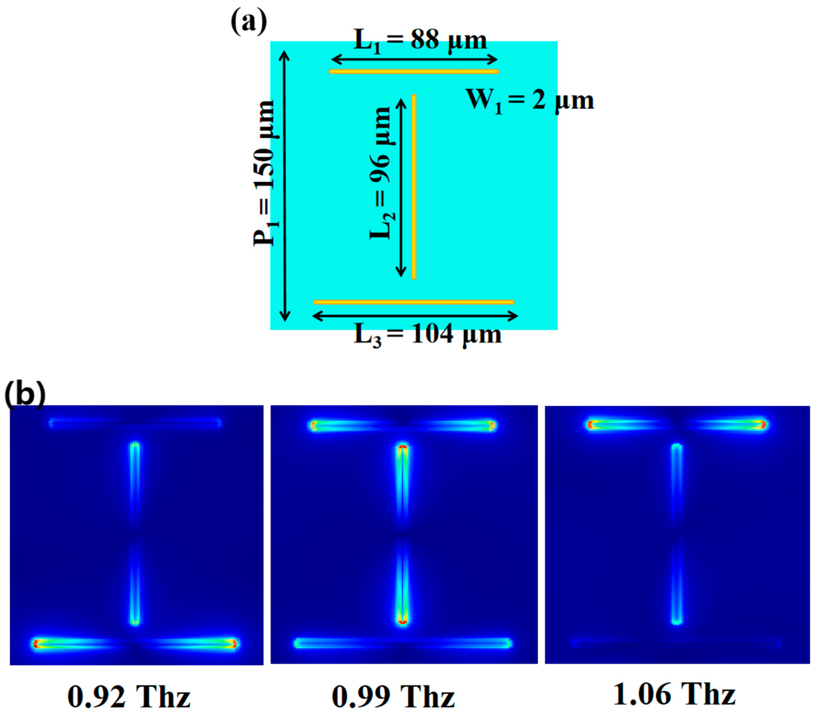
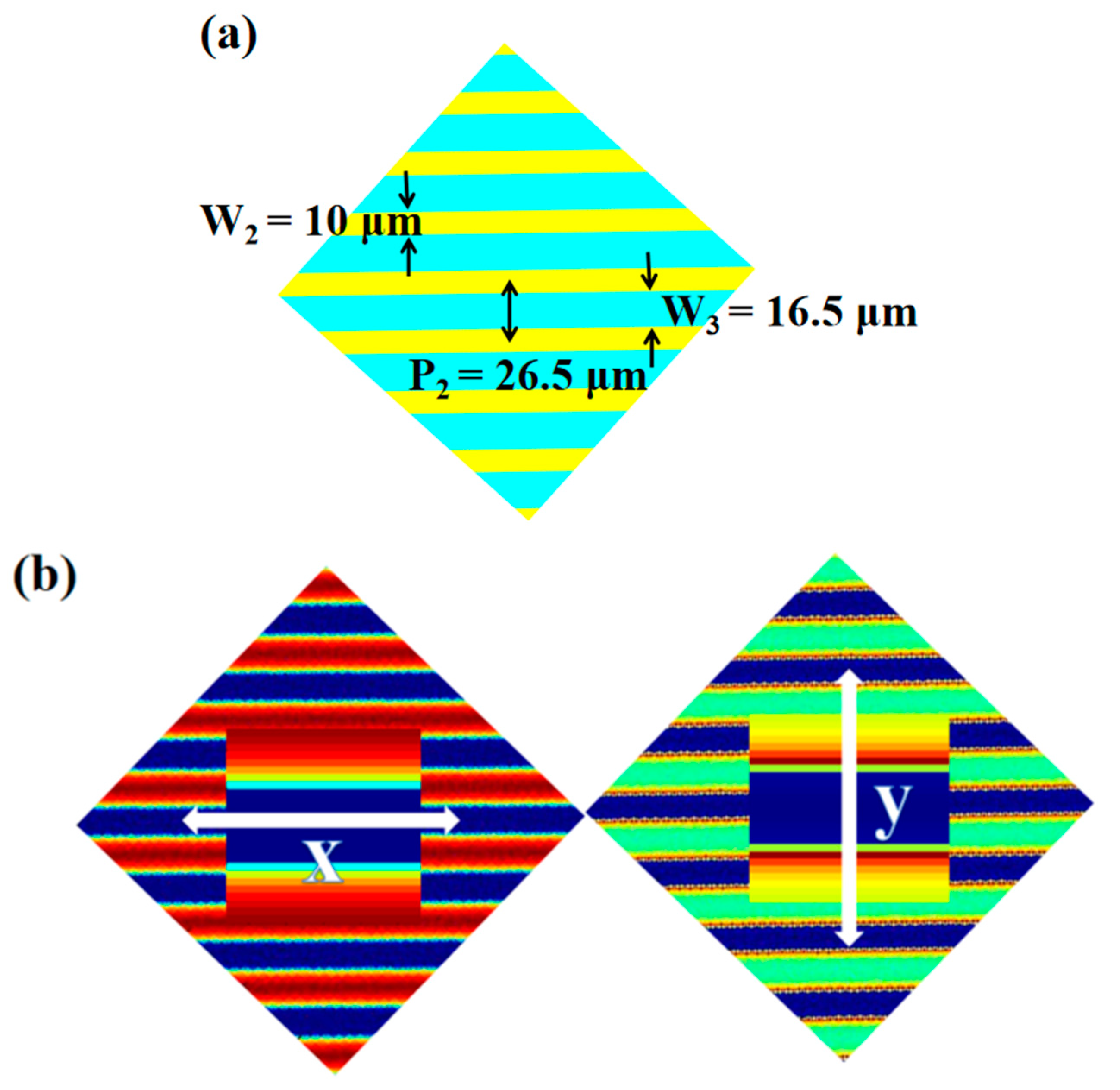
2. Structure Design and Theoretical Analysis

Figure 1 shows the schematic diagram of the proposed circular polarization detection structure. Incident circularly polarized light is converted to linear polarization by the quarter-wave plate. Polarizing filters can differentiate linearly polarized light, so the overall structure has different sensitivities for different rotations of circularly polarized light. The operation of this metasurface on a wavefront can be best described by using the Jones matrices. According to the Jones matrices, left-handed (Jones vector 2 2 [ 1 i ] ) and right-handed (Jones vector 2 2 [ 1 i ] ) polarized transmissions can be obtained [30,31]:
T R C P = 1 4 ( | T x T s e i ( Δ φ 2 + π 4 ) + T x T p e i ( Δ φ 2 + π 4 ) | 2 + | T y T s e i ( Δ φ 2 + π 4 ) + T y T p e i ( Δ φ 2 + π 4 ) | 2 ) T L C P = 1 4 ( | T x T s e i ( Δ φ 2 + π 4 ) + T x T p e i ( Δ φ 2 + π 4 ) | 2 + | T y T s e i ( Δ φ 2 + π 4 ) + T y T p e i ( Δ φ 2 + π 4 ) | 2 )
Here, Δ φ is the phase difference and T S and T P are the transmission coefficients of the quarter-wave plate for the electric field components along the fast and slow axes. T x and T y are the transmission coefficients of the polarizing Cu grating for the electric field components along the x and y axes. According to Equation (1), the maximum conversion efficiency occurs at Δ φ = ± π 2 . We design the dual-frequency quarter-wave plate to obtain the phase delay of ± π 2 .
Figure 2a shows the schematic diagram of the optimized quarter-wave plate, and L1 and L3 are parallel to the X-axis while L2 is perpendicular to the x-axis. The light source is set to linearly polarized light of 0.92 Thz, 0.99 Thz, and 1.06 Thz, and the included angle to the X-axis is 45°. Figure 2b shows the electric field, and Cu wires can obtain resonance and phase delays at different frequencies. Resonance occurs at both ends of the Cu lines, and the three Cu lines are spaced apart in order to avoid mutual interference. The phase difference between the X- and Y-polarized light can be generated by the positional arrangement of the Cu wires as described above. The polarization information of terahertz waves can be determined by the four Stokes parameters [32,33]:
S 0 = | t x | 2 + | t y | 2 S 1 = | t x | 2 | t y | 2 S 2 = 2 t x t y cos ( Δ φ ) S 3 = 2 t x t y sin ( Δ φ )
Here, Δ φ corresponds to the phase difference ( Δ φ = φ y φ x ). The ellipticity is defined as χ = S 3 / S 0 . χ = 1 indicates a right circular polarization. χ = 1 indicates left circular polarization. Ellipticity can evaluate the performance of the quarter wave plate. Figure 3 shows the phase delay (a) and ellipticity (b). The x electric field component produces two phase delays. They are excited by L1 and L3 parallel to the X-axis. The y electric field component produces one phase delay. It is excited by L2 parallel to the y-axis. L1 and L2 can generate a phase difference of π 2 for the x and y components. L3 and L2 can generate a phase difference of π 2 for the x and y components. The absolute value of ellipticity is greater than 0.99 in a range between 0.95~0.955 Thz and 1.026~1.033 Thz. This result indicates that the linearly polarized light is converted to a kind of elliptically polarized light that is very close to circularly polarized light. Therefore, our quarter wave plate can be realized at two frequencies.
Figure 4a shows the schematic diagram of the Cu grating. Here, P2 represents the length of one unit, W2 represents the width of the Cu wire, and W3 represents the width of the interval. Figure 4b shows the electric field of the Cu grating. The light parallel to the metallic strip cannot induce surface plasmons. Therefore, the incident light cannot be transmitted. Only the light perpendicular to the metallic strip can be coupled to surface plasmons modes. We consequently obtain a high zero-order transmission due to the excitation of coupled surface plasmons [34].

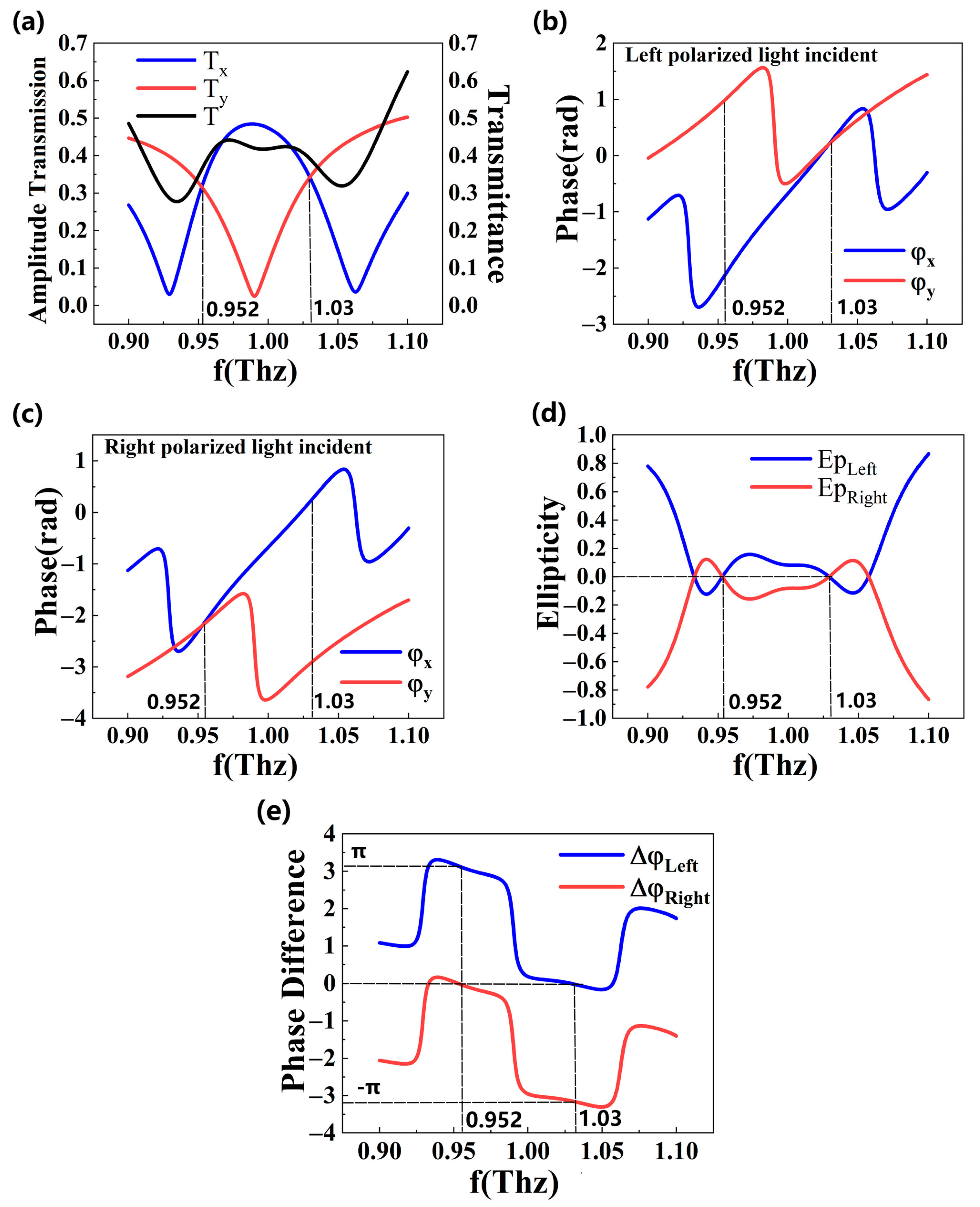
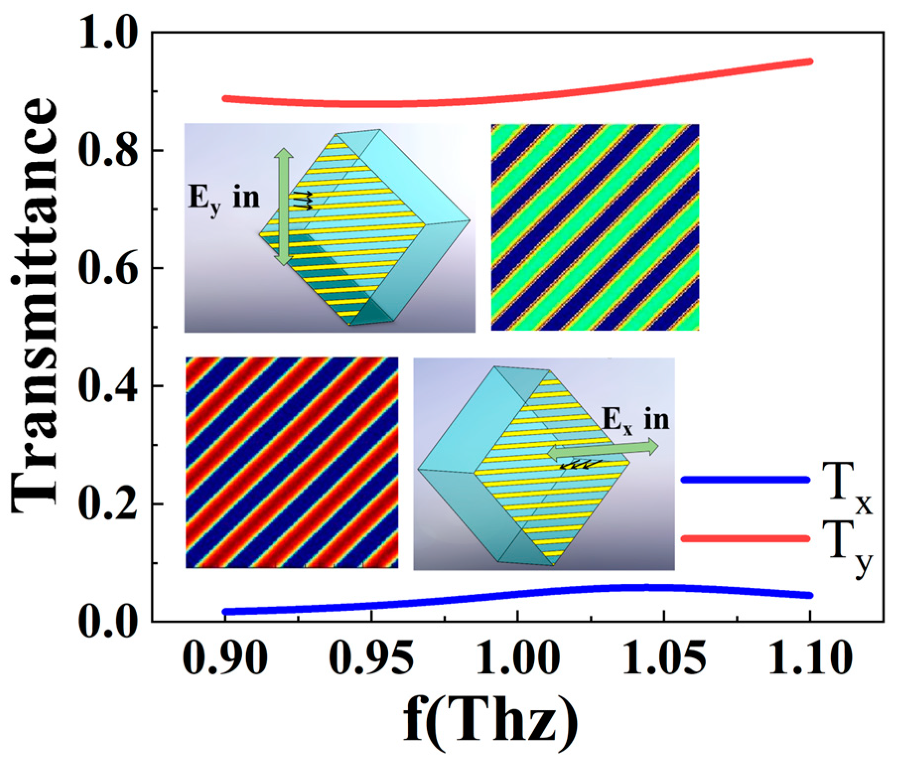
3. Results and Discussion

Although the Jones matrix can describe the manipulation process of the wave front by the metasurface, it cannot evaluate the effect of the reflection inside the structure. In order to study the properties of the circular polarization detection structure, we use the commercial software FDTD solution (Version 2020 R2.1) for simulations. We first verify the performance of the quarter-wave plate. In the simulation, the thickness of Cu is 0.5 μm, and its conductivity is 5.8 × 10⁷ S/m. A polyimide layer with a thickness of 200 μm separates the two layers. The polyimide substrate layer is a dielectric with a relative dielectric constant of 3. We first investigate the effect of the length and width of Cu wire on phase regulation. The light source is set to y-polarized light. The Cu wire is parallel to the Y-axis. Figure 5a,b shows the effect of different Cu wire lengths on amplitude and phase. The excitation of surface plasmon resonance can severely weaken the transmission efficiency. The amplitudes of the electromagnetic waves are all less than 0.05 at the five resonant frequencies. It can be found that the frequency, which causes resonance, increases along with the increased length of Cu wires. The effect on the amplitude and phase is small. Figure 6 shows the effect of different Cu line widths on the phase. It can be found that the larger the width is, the higher the phase delay, and the resonant frequency is slightly smaller. This may be due to the fact that larger volumes of Cu wires require longer wavelengths to excite resonance. The design requirements of the quarter-wave plate are that the x and y components have the same amplitude, and the phase difference is π 2 . Therefore, the width of our Cu wire is set to 2 μm. Higher widths can be used to design devices with higher phase retardation, such as half-wave plates. We chose the 96 μm Cu wire to induce phase retardation in the Y-direction and the 88 μm and 104 μm Cu wires to induce phase retardation in the X-direction.
The performance of the quarter-wave plate is shown in Figure 7. In the simulation, the source is set to x-and y-polarized light with a phase difference of ± π 2 (simulated left-handed polarized light and right-handed polarized light, respectively). In Figure 7, Tx and Ty represent the amplitude of the x and y components, while φ x and φ y represent the phase of the x and y components. Δ φ represents the phase difference. T represents the transmittance. As we can see, the amplitudes of the two orthogonal polarization components are the same at 0.952 Thz and 1.03 Thz. This is one of the conditions for good performance of the quarter-wave plate. The transmittance is approximately 40% at these two frequencies. Figure 7b,e shows the phase and phase difference when the incident light is left-handed polarized light. When the frequency is 0.952 Thz, the phase difference of the x and y electric field components is π 2 . These two components can be superimposed to form a linearly polarized light. The angle of the transmitted linearly polarized light to the x-axis is −45°. When the frequency is 1.03 Thz, the phase difference of the x and y electric field components is 0. The transmitted light is still linearly polarized. The angle of the transmitted light to the x-axis is 45°. When the incident light is right-handedly polarized, the result is the opposite. Figure 7c–e shows the phase and phase difference when the incident light is right-handed polarized light. As the frequency is 0.952 Thz, the phase difference is 0. The angle of the transmitted light to the x-axis is 45°. As the frequency increases to 1.03 Thz, the phase difference is π 2 . The angle of the transmitted light to the x-axis is −45°. Figure 7d shows the ellipticity. The ellipticity is 0 at 0.952 Thz and 1.03 Thz. This demonstrates the good conversion efficiency of our quarter-wave plate. Essentially, the opposite phase difference between the x and y components causes the different handedness of circularly polarized light. After the phase modulation via the quarter-wave plate, this difference in the handedness directionality of circularly polarized light is transformed into a difference in the deflection angle of linearly polarized light. Detecting the directional only angle requires a line filter, which is relatively easy to operate. Therefore, the conversion of polarization states is an important part of detecting circularly polarized light. Ultimately, we successfully design a quarter-wave plate that can work at both 0.952 Thz and 1.03 Thz. It can convert circularly polarized light of different handedness into linearly polarized light of different directions. The phase differences obtained at the two frequencies are opposite, so this leads to the opposite effect of detection.
In order to detect the directional angle of linearly polarized light, we designed the lower layer to serve as the linear filter. First, we investigated the effect of the width of Cu wire on the grating transmittance and extinction ratio. The grating is assumed to parallel the x-axis, incident with x- and y-polarized light, respectively. Figure 8 shows the transmittance and extinction ratio of the grating. When the Cu line is wider, the transmittance of the grating is lower, and the extinction ratio is higher. For example, when the line width is 2 μm, although the lower duty cycle brings higher transmittance, the extinction ratio is reduced, and the ability to distinguish the direction of polarized light is reduced. When the line width is 22 μm, although it has an excellent extinction ratio at this time, it greatly hurts the transmittance. Considering the practicality of the overall structure, we chose a line width of 10 μm while ensuring high transmittance and high extinction ratio.
Figure 9 shows the transmittance of wire grating. The transmittance of light parallel to the wire grid is less than 6% at 0.9~1.1 Thz. The transmittance of light perpendicular to the wire grid is over 89% at 0.9~1.1 Thz. The extinction ratio of the linear filter is greater than 15. Figure 10 shows the transmittance of circularly polarized detection structures. At 0.952 Thz, the transmittance of the left-handed polarized light is 40%, and the transmittance of the right-handed polarized light is 10%. The extinction ratio is 4:1. At 1.032 Thz, the transmittance of left-handed polarized light is 7.6%, and that of right-handed polarized light is 40%. The extinction ratio is 1:5.26. We changed the angle of the wire grating to the X-axis to −45°. The opposite effect is produced. As shown in Figure 10b, the detection function of this structure is the opposite of the previous one. Since they have almost the same transmission curve, they can be considered a pair of pixel units for circular polarization imaging. It can be seen that the structure we designed can distinguish the handedness of circularly polarized light. However, the extinction ratio is not the optimal value owing to two reasons: (1) The conversion efficiency of the quarter-wave plate is not 100% and (2) there is a mutual reflection between the two layers. Using dielectric materials may solve these problems, and the errors do not affect the functionality of our structure.

4. Conclusions

In conclusion, we have reported the numerical investigation of dual-frequency circular polarization detection using the finite-difference time-domain (FDTD) method. The functions of the quarter-wave plate, wire grating, and detection structure are verified. The structure we designed can work at both 0.952 Thz and 1.03 Thz. The detection effects of the two frequencies are opposite. The left polarized light can be transmitted at 0.952 Thz and the extinction ratio reaches 4 dB. The right polarized light can be transmitted at 1.03 Thz and the extinction ratio reaches 5.26 dB. The maximum transmittance efficiency is 40%. Compared with previous studies, the structure has dual-frequency characteristics and integration. Our findings are helpful for the development of miniature and multi-frequency polarization detection structures.

Author Contributions

Conceptualization, B.Y. and Y.F.; methodology, B.Y.; software, B.Y. and Y.Z. (Yu Zhao); validation, B.Y., Y.F. and Y.Z. (Yuhui Zhang); formal analysis, B.Y.; investigation, B.Y. and C.M.; resources, B.Y.; data curation, B.Y.; writing—original draft preparation, B.Y.; writing—review and editing, M.O. and H.R.; visualization, B.Y.; supervision, B.Y.; project administration, B.Y. and M.O.; funding acquisition, Y.F. and C.M. All authors have read and agreed to the published version of the manuscript.

Funding

This study received funding from te 111 Project of China (D21009, D17017), Science and technology research project of Education Department of Jilin Province (JJKH20210814KJ), National Natural Science Foundation of China (61705018), Jilin Province Science and Technology Development Plan Project (20200403107SF), Jilin Province Science and Technology Development Plan Project (20210204191YY), and Changchun University of Science and Technology Youth Science Fund Project (XQNJJ-2017-08).

Institutional Review Board Statement

Not applicable.

Informed Consent Statement

Not applicable.

Data Availability Statement

Not applicable.

Conflicts of Interest

The authors declare no conflict of interest.

References

  1. Wu, P.C.; Chen, J.W.; Yin, C.W.; Lai, Y.C.; Chung, T.L.; Liao, C.Y.; Chen, B.H.; Lee, K.W.; Chuang, C.J.; Wang, C.M.; et al. Visible metasurfaces for on-chip polarimetry. ACS Photonics 2017, 5, 2568–2573. [Google Scholar] [CrossRef]
  2. Hao, J.; Yuan, Y.; Ran, L.; Jiang, T.; Kong, J.A.; Chan, C.T.; Zhou, L. Manipulating electromagnetic wave polarizations by anisotropic metamaterials. Phys. Rev. Lett. 2007, 99, 063908. [Google Scholar] [CrossRef] [Green Version]
  3. Rappaport, T.S.; Xing, Y.; Kanhere, O.; Ju, S.; Madanayake, A.; Mandal, S.; Alkhateeb, A.; Trichopoulos, G.C. Wireless communications and applications above 100 GHz: Opportunities and challenges for 6G and beyond. IEEE Access 2019, 7, 78729–78757. [Google Scholar] [CrossRef]
  4. Zhang, Y.; Qiao, S.; Liang, S.; Wu, Z.; Yang, Z.; Feng, Z.; Sun, H.; Zhou, Y.; Sun, L.; Chen, Z.; et al. Gbps terahertz external modulator based on a composite metamaterial with a double-channel heterostructure. Nano Lett. 2015, 15, 3501–3506. [Google Scholar] [CrossRef]
  5. Sabban, A. Wearable Circular Polarized Antennas for Health Care, 5G, Energy Harvesting, and IoT Systems. Electronics 2022, 11, 427. [Google Scholar] [CrossRef]
  6. Ranjbar, B.; Gill, P. Circular dichroism techniques: Biomolecular and nanostructural analyses-a review. Chem. Biol. Drug Des. 2009, 74, 101–120. [Google Scholar] [CrossRef]
  7. Choi, W.J.; Cheng, G.; Huang, Z.; Zhang, S.; Norris, T.B.; Kotov, N.A. Terahertz circular dichroism spectroscopy of biomaterials enabled by kirigami polarization modulators. Nat. Mater. 2019, 18, 820–826. [Google Scholar] [CrossRef]
  8. Giakos, G.C. Multifusion, multispectral, optical polarimetric imaging sensing principles. IEEE Trans. Instrum. Meas. 2006, 55, 1628–1633. [Google Scholar] [CrossRef]
  9. Zhang, Z.; Fan, F.; Shi, W.; Zhang, T.; Chang, S. Terahertz circular polarization sensing for protein denaturation based on a twisted dual-layer metasurface. Biomed. Opt. Express 2022, 13, 209–221. [Google Scholar] [CrossRef]
  10. Kim, M.; Rho, J. Metamaterials and imaging. Nano Converg. 2015, 2, 22. [Google Scholar] [CrossRef] [Green Version]
  11. Vedel, M.; Breugnot, S.; Lechocinski, N. Spatial calibration of full stokes polarization imaging camera[C]//Polarization: Measurement, Analysis, and Remote Sensing XI. Int. Soc. Opt. Photonics 2014, 9099, 90990I. [Google Scholar]
  12. McNichols, R.J.; Cote, G.L. Optical glucose sensing in biological fluids: An overview. J. Biomed. Opt. 2000, 5, 5–16. [Google Scholar] [CrossRef]
  13. Min, H.; Sekar, G.; Hilty, C. Polarization transfer from ligands hyperpolarized by dissolution dynamic nuclear polarization for screening in drug discovery. Chem. Med. Chem. 2015, 10, 1559–1563. [Google Scholar] [CrossRef]
  14. Saïdi, F.; Taulelle, F.; Martineau, C. Quantitative 13C solid-state NMR spectra by multiple-contact cross-polarization for drug delivery: From active principles to excipients and drug carriers. J. Pharm. Sci. 2016, 105, 2397–2401. [Google Scholar] [CrossRef]
  15. Aslan, K.; Lakowicz, J.R.; Geddes, C.D. Angular-dependent polarization-based plasmon light scattering for bioaffinity sensing. Appl. Phys. Lett. 2005, 87, 234108. [Google Scholar] [CrossRef]
  16. Zhang, M.; Hao, D.; Wang, S.; Li, R.; Wang, S.; Ma, Y.; Moro, R.; Ma, L. Chiral biosensing using terahertz twisted chiral metamaterial. Opt. Express 2022, 30, 14651–14660. [Google Scholar] [CrossRef]
  17. Pors, A.; Nielsen, M.G.; Bozhevolnyi, S.I. Plasmonic metagratings for simultaneous determination of Stokes parameters. Optica 2015, 2, 716–723. [Google Scholar] [CrossRef] [Green Version]
  18. Zhang, Y.; Fu, Y.; Ma, C.; Yang, B.; Zhao, Y. Research on Fabrication Techniques and Focusing Characteristics of Metalens. Coatings 2022, 12, 359. [Google Scholar] [CrossRef]
  19. Khorasaninejad, M.; Crozier, K.B. Silicon nanofin grating as a miniature chirality-distinguishing beam-splitter. Nat. Commun. 2014, 5, 5386. [Google Scholar] [CrossRef] [Green Version]
  20. Shaltout, A.; Liu, J.; Kildishev, A.; Shalaev, V. Photonic spin Hall effect in gap–plasmon metasurfaces for on-chip chiroptical spectroscopy. Optica 2015, 2, 860–863. [Google Scholar] [CrossRef]
  21. Wen, D.; Yue, F.; Kumar, S.; Ma, Y.; Chen, M.; Ren, X.; Kremer, P.E.; Gerardot, B.D.; Taghizadeh, M.R.; Buller, G.S.; et al. Metasurface for characterization of the polarization state of light. Opt. Express 2015, 23, 10272–10281. [Google Scholar] [CrossRef]
  22. Khorasaninejad, M.; Chen, W.T.; Zhu, A.Y.; Oh, J.; Devlin, R.C.; Rousso, D.; Capasso, F. Multispectral chiral imaging with a metalens. Nano Lett. 2016, 16, 4595–4600. [Google Scholar] [CrossRef]
  23. Arbabi, E.; Kamali, S.M.; Arbabi, A.; Faraon, A. Full-Stokes imaging polarimetry using dielectric metasurfaces. ACS Photonics 2018, 5, 3132–3140. [Google Scholar] [CrossRef] [Green Version]
  24. Politano, G.G.; Versace, C. Variable-Angle Spectroscopic Ellipsometry of Graphene-Based Films. Coatings 2021, 11, 462. [Google Scholar] [CrossRef]
  25. Dmitriev, V.; Nascimento, C.; Lima, R.; Prosvirnin, S.L. Controllable frequency and polarization TH z filter based on graphene fish-scale metamaterial. Microw. Opt. Technol. Lett. 2017, 59, 3115–3118. [Google Scholar] [CrossRef]
  26. Barkabian, M.; Sharifi, N.; Granpayeh, N. Multi-functional high-efficiency reflective polarization converter based on an ultra-thin graphene metasurface in the THz band. Opt. Express 2021, 29, 20160–20174. [Google Scholar] [CrossRef]
  27. Liu, M.; Hwang, H.Y.; Tao, H.; Strikwerda, A.C.; Fan, K.; Keiser, G.R.; Sternbach, A.J.; West, K.G.; Kittiwatanakul, S.; Lu, J.; et al. Terahertz-field-induced insulator-to-metal transition in vanadium dioxide metamaterial. Nature 2012, 487, 345–348. [Google Scholar] [CrossRef]
  28. He, H.; Shang, X.; Xu, L.; Zhao, J.; Cai, W.; Wang, J.; Zhao, C.; Wang, L. Thermally switchable bifunctional plasmonic metasurface for perfect absorption and polarization conversion based on VO2. Opt. Express 2020, 28, 4563–4570. [Google Scholar] [CrossRef]
  29. Yu, F.; Zhu, J.; Shen, X. Tunable and reflective polarization converter based on single-layer vanadium dioxide-integrated metasurface in terahertz region. Opt. Mater. 2022, 123, 111745. [Google Scholar] [CrossRef]
  30. Basiri, A.; Chen, X.; Bai, J.; Amrollahi, P.; Carpenter, J.; Holman, Z.; Wang, C.; Yao, Y. Nature-inspired chiral metasurfaces for circular polarization detection and full-Stokes polarimetric measurements. Light: Sci. Appl. 2019, 8, 78. [Google Scholar] [CrossRef]
  31. Xu, M.; Cao, Y.; Sun, X.; Miao, Y.; Dong, X.; Zhang, Y.; Gao, X. Circular polarization detection metasurface inspired by the polarized vision of mantis shrimp. Opt. Commun. 2022, 507, 127599. [Google Scholar] [CrossRef]
  32. Han, Z.; Ohno, S.; Tokizane, Y.; Nawata, K.; Notake, T.; Takida, Y.; Minamide, H. Off-resonance and in-resonance metamaterial design for a high-transmission terahertz-wave quarter-wave plate. Opt. Lett. 2018, 43, 2977–2980. [Google Scholar] [CrossRef] [PubMed]
  33. Cong, L.; Xu, N.; Gu, J.; Singh, R.; Han, J.; Zhang, W. Highly flexible broadband terahertz metamaterial quarter-wave plate. Laser Photonics Rev. 2014, 8, 626–632. [Google Scholar] [CrossRef]
  34. Brand, G.F. The strip grating as a circular polarizer. Am. J. Phys. 2003, 71, 452–456. [Google Scholar] [CrossRef]
Figure 1. Schematic diagram and function of the structure of circular polarization detection. The upper layer is a quarter-wave plate consisting of mutually orthogonal Cu lines. The lower layer is a Cu wire grid and is oriented at 45° to the horizontal. In the terahertz band, metallic Cu can induce the excitations of surface plasma. Therefore, it can be used to design quarter-wave plates and filters. The two layers of metal are spaced apart by polyimide. The polyimide is transparent at this frequency and has a certain bending resistance. Therefore, it is an ideal material for use as a dielectric layer.
Coatings 12 00736 g001
Figure 2. (a) Schematic diagram of the quarter-wave plate, where P1 represents the length of one unit cell, L1, L2, and L3 represent the length of the Cu wire, and W1 represents the width of the Cu wire. (b) The electric field of one unit cell on the metasurface at 0.92 Thz, 0.99 Thz, and 1.06 Thz.
Coatings 12 00736 g002
Figure 3. (a) Correspondence of the phase delay of the x and y electric field components with frequency. (b) Correspondence of frequency with phase difference and ellipticity.
Coatings 12 00736 g003
Figure 4. (a) Schematic diagram of the Cu grating. (b) Electric field of the Cu grating when the x- and y-polarized light is incident, respectively.
Coatings 12 00736 g004
Figure 5. (a) Effect of Cu wire length on amplitude and resonance frequency. (b) Effect of Cu wire length on phase delay and resonance frequency.
Coatings 12 00736 g005
Figure 6. Effect of Cu line width on phase delay and resonance frequency.
Coatings 12 00736 g006
Figure 7. Correspondence between the performance parameters of the quarter-wave plate and the frequency. (a) Amplitude and transmittance of the x and y electric field components. (b) Phase delay of the x and y electric field components (left polarized light incident). (c) Phase delay of the x and y electric field components (right polarized light incident). (d) The ellipticity of the outgoing light. (e) The phase difference between the x and y electric field components of the outgoing light.
Coatings 12 00736 g007
Figure 8. Effect of Cu line width on the (a) transmittance and (b) extinction ratio of the grating in the frequency range 0.9–1.1 Thz.
Coatings 12 00736 g008
Figure 9. Transmittance and electric field of the wire grid when x- and y-polarized light is incident.
Coatings 12 00736 g009
Figure 10. Correspondence between transmittance and frequency of circularly polarized detection structures. (a) The angle of the wire grating to the X-axis to 45°. (b) The angle of the wire grating to the X-axis to −45°.
Coatings 12 00736 g010aCoatings 12 00736 g010b
Publisher’s Note: MDPI stays neutral with regard to jurisdictional claims in published maps and institutional affiliations.

