Article

PANI-Based Stacked Ferromagnetic Systems: Electrochemical Preparation and Characterization

by
Andrea Stefani
1,2,3,
Natàlia Tanaka Fonollosa
4,
Walter Giurlani
3,5,
Roberto Giovanardi
1 and
Claudio Fontanesi
1,3,*
1
Department of Engineering ‘Enzo Ferrari’, University of Modena and Reggio Emilia, Via Vivarelli 10, 41125 Modena, Italy
2
Department of Physics, Informatics and Mathematics ‘FIM’, University of Modena and Reggio Emilia, Via Giuseppe Campi, 213, 41125 Modena, Italy
3
National Interuniversity Consortium of Materials Science and Technology (INSTM), Via G. Giusti 9, 50121 Firenze, Italy
4
Department of Chemical Engineering and Analytical Chemistry, University of Barcelona, 08007 Barcelona, Spain
5
Department of Chemistry “Ugo Schiff”, University of Florence, Via della Lastruccia 3, 50019 Sesto Fiorentino, Italy
*
Author to whom correspondence should be addressed.
Coatings 2022, 12(10), 1518; https://doi.org/10.3390/coatings12101518
Submission received: 13 June 2022 / Revised: 15 September 2022 / Accepted: 23 September 2022 / Published: 10 October 2022

Abstract

:
In this work, the electropolymerization of polyaniline (PANI) is explored for its action as either a suitable coating or as a substrate for Nickel (Ni) and Magnetite (Fe3O4) surfaces. PANI electropolymerization has been achieved through cyclic voltammetry (CV), potentiostatic and galvanostatic electrochemical methods. The interaction between the obtained surfaces and the ferromagnetic layers (Ni and Fe3O4) has been investigated as a function of the pH of the electrolytic PANI solution, and also a variety of experimental parameters have been optimized in order to achieve the synthesis of PANI coatings (solvent, substrate, concentrations, and cell set-up). Thus, we obtained stable and consistent PANI thick films at the interface of both the nickel and the magnetite ferromagnetic materials.

1. Introduction

Conductive Polymers (CPs) are a widespread category of materials, which feature some mechanical attributes of plastics with the typical electrical properties of semiconductors; these species contain conjugated bonds, which give rise to an almost continuous valence and conduction bands [1]. Moreover, CPs are usually characterized by optical transparency in the oxidized state and by a modulable band gap [2]. This is the reason why conductive polymers are used for many different applications that include catalysis [3], electroluminescent devices [4,5], organic transistors [6,7,8], LEDs [9,10] and photovoltaic polymer cells [11,12,13]. With respect to ordinary inorganic semiconductors, CPs hold particular advantages, such as a low switching time [14], a high contrast ratio (CR) [15] and a modulable bandgap [16]. By oxidizing or reducing the polymeric chains of CPs (via chemical or electrochemical procedure), it is possible to generate charge centres, which are responsible for the electrical conductivity of these species [17].
One of the most important conductive polymers is polyaniline (PANI), which can be obtained by the chemical or electrochemical polymerization of aniline, a phenyl ring attached to an amino group (see Figure 1a). Unlike other CPs, polyaniline can exist in different forms, depending on the degree of oxidation. Polyaniline is formed by monomer units built from reduced (y) and oxidized (1-y) groups, with 0 ≤ y ≤ 1 (compare with Figure 1b) [18]. The redox state of the polymer is determined by the value of y:
At y = 0, polyaniline is in the form of pernigraniline, the fully oxidized form; if y = 0.5, polyaniline is in the form of emeraldine, while y = 1 corresponds to the form of leucoemeraldine (the fully reduced form).
In addition, the transitions between different polyaniline forms (and consequently different oxidations levels) are characterized by changes in many physical properties, such as color and conductivity. The maximal conductivity of polyaniline is achieved at a doping degree of 50%, which corresponds to polyaniline in the form of emeraldine salt [19]. For higher doping degrees, some of the amine sites (-NH-) are protonated, while lower doping degrees mean that some of the imine (=NH-) sites are left unprotonated [20]. Therefore, the reduction of emeraldine salt to leucoemeraldine and the oxidation to pernigraniline states decrease the conductivity (in accordance with the polaron conductivity model) [21]. The order of magnitude for conductivity varies from 10−2 S cm−1, for undoped emeraldine, to 103 S cm−1, for doped emeraldine salt [22].
The mechanism and the kinetics of the electrochemical polymerization of aniline were intensively studied [22,23,24,25,26,27,28,29,30]. Nevertheless, in the context of applications, aniline polymerization is typically only performed in an acidic environment, since a higher pH results in short and conjugated bonds as the protonation is favoured [20].
In this work, the electrochemical polymerization of PANI was investigated, with particular attention paid to the interaction possibility with ferromagnetic materials and magneto-responsive devices, in the context of a simple electrochemical production [31,32,33,34,35,36]. The galvanostatic and potentiodynamic electropolymerization of aniline has been explored as a function of the pH of the electrolytic solution, allowing one to produce stacked systems with ferromagnetic layers.

2. Materials and Methods

Sigma Aldrich (Burlington, MA, USA) Aniline ACS reagent 95%, Sigma Aldrich Iron (III) sulphate hydrate Fe2(SO4)3 97%, Sigma Aldrich Sulfuric acid H2SO4 ≥ 99.9%, Sigma Aldrich Acetic acid CH₃COOH ACS reagent ≥ 99.7%, Sigma Aldrich Sodium hydroxide Na(OH) ≥ 98%, Sigma Aldrich Potassium chloride KCl ≥ 99%, Carlo Erba Boric acid H3BO3 99+%, Carlo Erba Nickel (II) chloride, anhydrous 98%, Sigma Aldrich Nickel (II) sulphate anhydrous 99.99% and Sigma Aldrich Triethanolamine ≥ 99.0% were used without additional manipulation. Regarding the electrochemical setup, PANI electropolymerization studies and ferromagnetic metals depositions were performed in a one-compartment, three-electrode electrochemical cell. A Pt wire was used as a counter-electrode (CE), while a Ag/AgCl/KClsat was the reference-electrode (Ref). The employed substrates (acting as working electrodes) consisted of gold (Au)-rod commercial electrodes by Metrohm (3 mm diameter) and gold Au surfaces (100 nm) evaporated on top of silicon wafers (1.5 × 1.5 cm2), with a 10 nm adhesion mid-layer. For the latter, a circular O-ring (1 cm diameter) was used in order to obtain a consistent value of the geometrical electrode area, thus making currents comparable. Prior to each electrochemical experiment, the working electrodes (WEs) were cleaned by sonication in EtOH, then rinsed with AcOH and distilled water, and finally dried with N2. The electropolymerization and metallization measurements were performed by means of cyclic voltammetry (CV) and both chronoamperometric and galvanostatic methods in unstirred solutions. The PANI electropolymerization solutions consisted of aniline (0.1 M) dissolved in different aqueous electrolytes, in sequence: H2SO4 (1 M), CH₃COOH (40 mM), KCl (0.1 M) and Na(OH) (0.1 M). Nickel was electrodeposited from a standard Watt’s Bath (WB), whose composition is: nickel sulphate NiSO4 (1 M), nickel chloride NiCl2 (0.25 M), boric acid H3BO3 (0.6 M), pH = 5. The magnetite electrodeposition solution [37] consisted of Na(OH) (2 M), Fe(III)2(SO4)3 (50 mM), TEA (0.1 M) (triethanolamine); the solution was prepared by slowly adding Fe(III)2(SO4)3 dissolved in water to a stirred solution of Na(OH) and TEA at 60 °C. All the electrochemical experiments were performed by means of an AUTOLAB PGSTAT type III, using NOVA electrochemistry software (version 2.1.5) from Metrohm Autolab. PANI was electropolymerized at different values of constant current (0.0625 mA, 0.125 mA, 0.250 mA, 0.5 mA, 0.75 mA) for different time intervals (900 s, 1800 s). The morphology of the surfaces and the relative cross sections were investigated by means of SEM photomicrographs performed using a Philips XL40 microscope; the section was obtained by cutting the samples with a REMET Micromet and mechanically polished using a Buehler Minimet 1000 (Buehler emery paper and alumina 0.05 μm). The profilometry measurements were performed using a HommelWerke Waveline20 profilometer. Monte Carlo simulations on the EDS microanalysis data have been performed using the software DTSA-|| [38].

3. Results

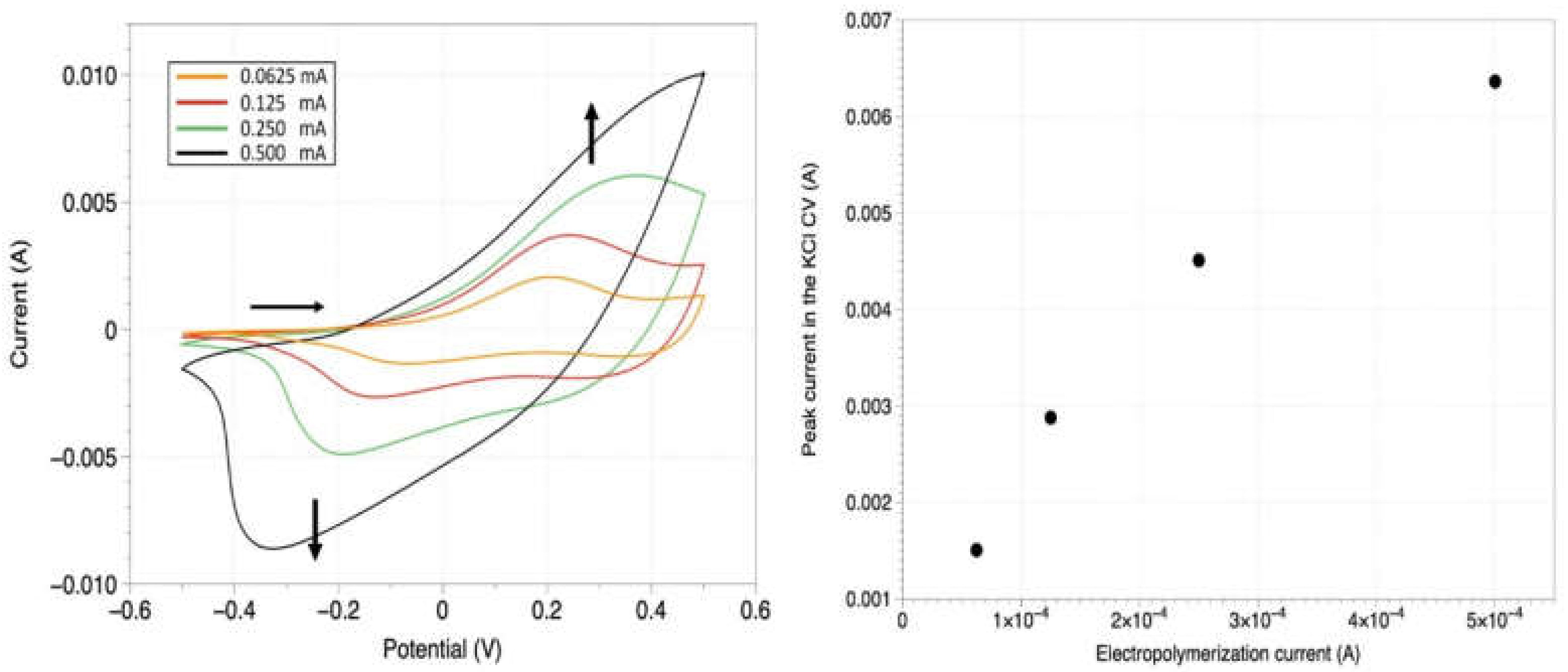
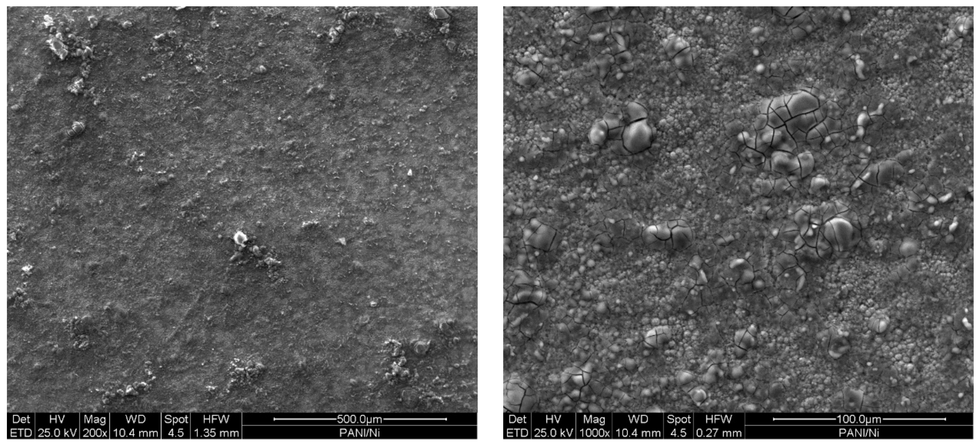
3.1. PANI Electropolymerization from Acidic Solution

The standard conditions for PANI electropolymerization include an acidic environment, typically provided by sulfuric acid or perchloric acid in an aqueous solution [39,40]. In our study, galvanostatic and potentiostatic PANI depositions, Figure 2, Figure 3 and Figure 4 were performed on a Au substrate from a H2SO4 (1 M) and aniline (0.1 M) electrolytic solution (please compare the following Section 3.3 for the CV method of electropolymerization). Figure 2 displays the potential (V) vs. time (t) trend for a PANI galvanostatic deposition. The polymer coating is grown by applying a constant current of 0.25 mA.
Figure 2 evidences an initial transient, where the potential reaches 0.75 V to match the imposed current. During these first seconds, the double-layer charging process is occurring; then, after the correspondent value of the potential is set, the diffusion dynamics take over, and the potential is approximately constant for the remaining time. The trend of the curve decreases slightly because a new conductive surface is growing on the electrode as PANI is polymerized, and so a lower potential is needed to maintain the imposed value of the current. The PANI coating obtained in the described procedure is illustrated in Figure 2 inset. The deposit is uniform, firmly adherent to the substrate, and shows a dark green colour (further evidence that PANI in the form of emeraldine has been synthetized, as expected when using acidic medium).
The relationship between the PANI thickness and the imposed current during the galvanostatic electropolymerization has been investigated by means of CV in support electrolyte (KCl), and the results are presented in Figure 3.
Figure 3 (left) features CV curves in the same potential window (−0.5 V ÷ 0.5 V) for different PANI coatings, which were deposited under the same conditions previously described but with different values of the constant current. Since the electrolytic solution only consists of support electrolyte, the observed current is associated with the PANI electrode reversible redox activity (oxidation peak between 0.2 V and 0.4 V, correspondent reduction peak between −0.2 V and −0.4 V). As the polymerization current increases (at a constant time, in this case 900 s), the thickness of the produced surface grows as well. A greater amount of conductive surface (for higher PANI thicknesses) results in a larger number of sites for the electrons’ exchange and correspondent higher currents displayed in the CVs. In Figure 3 (right), it can be observed that there exists a rough semiquantitative monotonic pattern between the current for the PANI electro-polymerization (galvanostatic regime) and the currents obtained in the KCl CVs. This trend is confirmed after repeating this experiment with a ferrocyanide/ferricyanide [Fe(III)(CN)6]3−/[Fe(II)(CN)6]4− redox probe in solution, as reported in the Supplementary Materials (Figure S1). The pattern emerging from Figure 3 shows that the doubling of the electropolymerization current translates to a thickness increase by a coefficient between 1.4 (for higher thicknesses i.e., a lower curve gradient) and 1.9 (small thicknesses, a higher gradient of the quadratic curve). This result is confirmed by the PANI thickness measurements which were performed on different samples and with different techniques (SEM top view and cross-section imaging, profilometry and Monte Carlo simulations on SEM EDS data, respectively, in Figure 5, Figure 6 and Figures S3 and S5). All these latter experiments show consistent results with the electrochemical data.

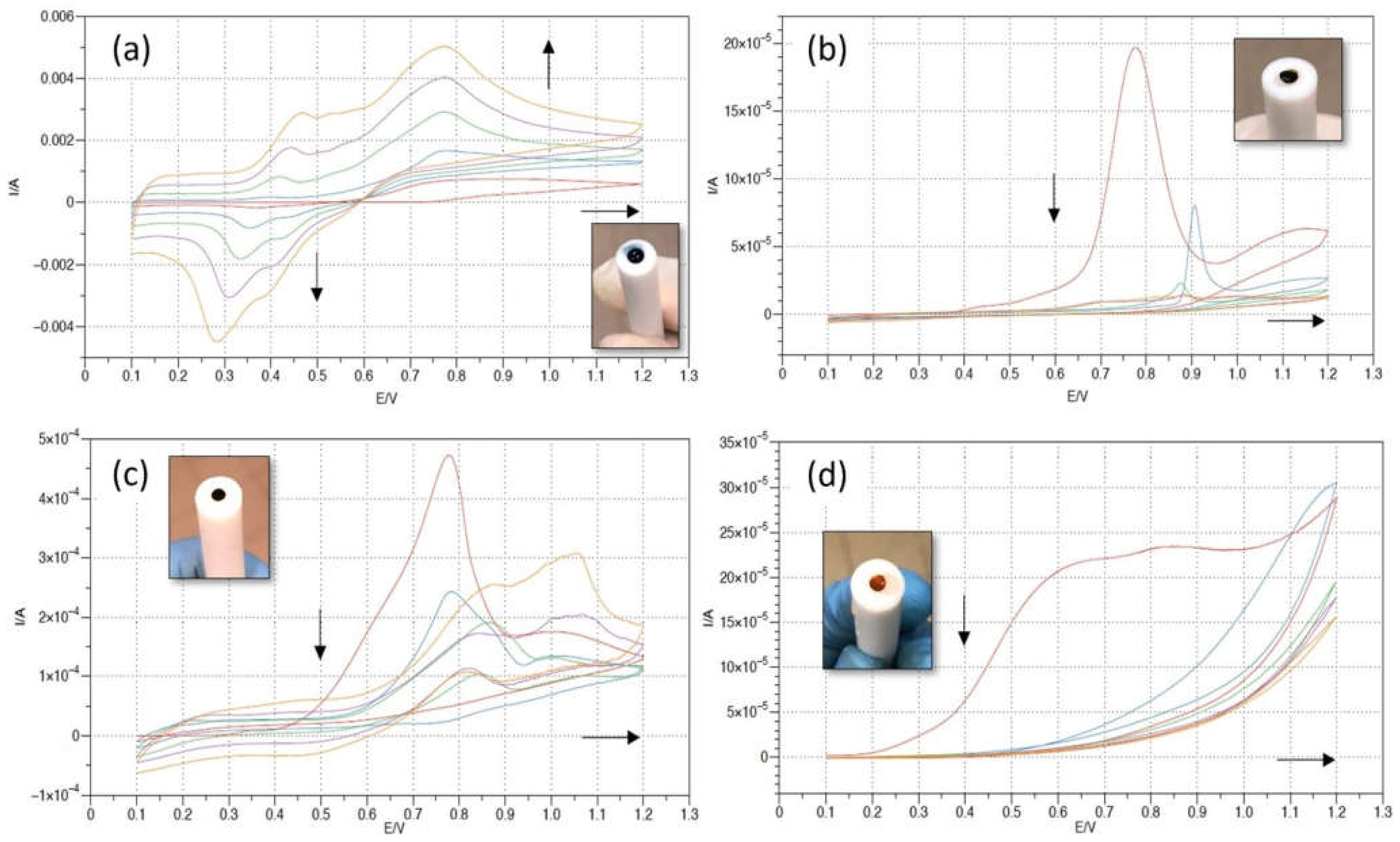
3.2. Ni Electrodeposition on Top of PANI

Nickel electrodepositions on top of the Au|PANI interface have been carried out as the conclusion of this simple 2-step process, allowing for the production of a hybrid layered electronic device. (PANI-Nickel systems are extensively used in multiple applications [41,42,43].)
Figure 4 reports a potentiostatic Ni deposition performed on an Au|PANI Working Electrode for 1800 s, at a constant reduction potential of −1.4 V vs. Ag/AgCl. The underlying Au|PANI interface was previously produced by 900 s, 0.125 mA constant current electrodeposition, following the exact same procedure described in Section 3.1. In the inset, a picture of the electrode after only 300 s of electrochemical Ni deposition is shown. Since the process is not complete yet, it is possible for one to appreciate the metallic layer growing on the green PANI surface, starting as expected from the edges of the electrode (stronger electric field force line). In fact, the electrode does not even need to be disassembled from the electrochemical cell between the two depositions. The only required middle step is vacuum-drying for approximatively 30 min, in order for the Nickel layer to adhere properly to the PANI surface.
Figure 5 presents the SEM top view of the fabricated device. The acquisition is performed with secondary electrons at 200× and 1000× magnifications (further SEM characterization can be found in the Supplementary Materials). The metallic Ni layer exhibits a compact morphology with globular-like crystallites, proving a good adhesion on the PANI substrate. The presence of micro-cracking (which is only noticeable at a 1000× magnification, corresponding to the bigger crystals) may be due to H2 evolution during the cathodic electrodeposition or to internal tensions releasing, associated to superficial oxidation.
Figure 6 shows a SEM cross-section image of the produced specimen, with a relative EDS microanalysis, where all the different elements of the layered structure can be appreciated. The acidic PANI mid-layer (0.125 mA for 900 s) is about 2.4 μm thick and follows the thin Au substrate (100 nm, evaporated on top of a Silicon wafer with a 10 nm Ti adhesion layer in between) very closely, suggesting a good adhesion. The Ni top coating is mainly metallic, with a very weak Oxygen signal in the bulk region (typical of galvanic metallization).

3.3. PANI Electropolymerization at Different pHs

The study of different PANI structures as a function of the pH of the electropolymerization solution arises from the need to coat an electrodeposited layer of Magnetite (Fe3O4) with PANI. In fact, while the above-mentioned Nickel is deposited from an acidic bath, Magnetite quickly dissolves in H2SO4 [44], and therefore it is not possible to expose a Fe3O4 surface directly to the acidic aniline solution. Consequently, a systematic investigation is carried out, electropolymerizing aniline from three further electrolytic baths:
-
weakly acidic solution (CH3COOH (40 mM), aniline (0.1 M), pH = 3, Figure 7b)
-
neutral solution (NaCl (0.1 M), aniline (0.1 M), pH = 7, Figure 7c)
-
basic solution (NaOH (0.1 M), aniline (0.1 M), pH = 13 Figure 7d)
The electropolymerization in these three additional environments is performed through a CV procedure, and it is compared to the H2SO4 electrolyte one (Figure 7a). All these depositions are carried out on Au substrates (MetrOhm Au electrodes), and the results are listed in Figure 7.
Figure 7a shows a potentiodynamic PANI polymerization in the standard H2SO4 medium (the system investigated in Section 3.1). The CV shows that the current increases in every successive cycle, which confirms the electrodeposition of the PANI film. In the forwards scans, the positive current peaks at 0.45 V and 0.75 V can be related to the leucoemeraldine base transition to emeraldine and to the following emeraldine oxidation to pernigraniline, respectively [45]. In the backwards scans, two corresponding reduction peaks are evidenced at about 0.4 V and 0.3 V, showing a good reversibility. As the number of cycles increases, the oxidation peaks shift to higher potential values and the reduction peaks shift to lower potential values. The electropolymerized polyaniline is green (as shown in the related inset), as expected for PANI in the form of emeraldine.
Figure 7b–d represent the PANI electropolymerization in the CH3COOH, NaCl and NaOH electrolyte, respectively. In all three CVs, the oxidation peak between 0.7 V and 0.8 V is still recognizable, and it is related to the aniline oxidation (and allows the polymerization). Nonetheless, the current decreases in every successive cycle (in contrast to Figure 7a), and the full-scale values for the current are more than one order of magnitude lower. The reduction peaks between 0.25 V and 0.35 V associated with the leucoemeraldine-emeraldine transformation are absent. The color of the deposited film switches from very dark green (almost black), in Figure 7b,c, to dark orange in the basic solution case (Figure 7d).

3.4. PANI Electropolymerization on Top of Magnetite

The basic aniline solution is used to electropolymerize PANI on a Fe3O4 electrode. Fe3O4 was previously electrodeposited on a Au substrate following a standard procedure [37]: the electrolytic solution consisted of Na(OH) (2 M), Fe2(SO4)3 (50 mM) and TEA (0.1 M). The Au WE underwent a potentiostatic electrodeposition at −1.3 V vs. Ag/AgCl for 1800 s (the deposition curve is reported in Figure S2 in the Supplementary Materials).
In the PANI electropolymerization on top of magnetite, the same recipe from Figure 7d (consisting of Na(OH) (0.1 M), aniline (0.1 M), pH = 13) acts as the electrolyte, and the Au|Fe3O4 interface acts as the WE. Figure 8 displays the galvanostatic PANI deposition, which was performed while imposing a constant current of 0.6 mA.
As expected, the conductivity of the basic PANI is much lower than the emeraldine, described in Section 3.1, since the protonation of the imine sites is largely prevented due to the basic environment. As a result, the obtainable thicknesses with an electrochemical polymerization are much thinner, at most 500 nm, according to our experiments. In fact, thicker coatings act as an insulator and break the contact with the electrode, making the continuation of the electrochemical procedure impossible.
Figure 9 displays the SEM top-view of the Fe3O4/PANI device. The acquisition is performed with secondary electrons at 200× and 1000× magnifications (further SEM characterization can be found in the Supplementary Materials). In particular, in the left image (200× magnification), the interface between the substrate (Au), magnetite and PANI can be distinguished, since the different coatings have been deposited with a stepped structure. (The good adhesion between the uniform layers is appreciable in the Figure 10 cross section.) The 1000× magnification picture presents the basic PANI top layer in detail and evidences the organic coating’s uniformity.
Figure 10 shows a SEM cross-section image of the produced Au|Fe3O4|PANI interface specimen, with a relative EDS microanalysis. A columnar morphology of the metallic ferromagnetic mid-layer can be observed, while the PANI top layer proves to be around 400 nm thick.

4. Conclusions

In this work, aniline electropolymerization has been studied with the prospect of coupling the PANI organic layer with a ferromagnetic material, producing a stacked hybrid system. In particular, the pH of the electropolymerization bath has been optimized for a suitable co-electrodeposition of Nickel (Ni) and Magnetite (Fe3O4), thus allowing for an easy and flexible way to manufacture the entire sample by electrochemical methods. Different electrochemical regimes have been explored, and an extensive characterization has been performed on the obtained systems. The electrochemical data, SEM surface and cross-section analysis, EDS microanalysis data and simulations, and profilometry measurements define a consistent comparison between the different PANI organic coatings.

Supplementary Materials

The following supporting information can be downloaded at: https://www.mdpi.com/article/10.3390/coatings12101518/s1, Figure S1: (a) Cyclic voltammetry (CV) curves recorded on PANI/Au WEs. The several colours are associated with separate samples which underwent different currents of electropolymerization, leaving unaltered all the other parameters (electrochemical bath, electropolymerization time of 900 seconds, substrate, electrode area…). (b) Relation between the oxidation peak current of Fe2+ recorded in Figure (a) CVs and the value of the imposed current during the electropolymerization of the samples; Figure S2: Magnetite (Fe3O4) potentiostatic deposition on a Au WE, in a 3-electrodes cell. Pt was used as CE, Ag/AgCl/KClsat as Ref. The electrolyte consisted in 2 M NaOH, 50 mM Fe2(SO4)3 and 0.1 M TEA. A constant reduction potential of −1.4 V was applied for 1800 seconds; Figure S3: Profilometry analysis performed on a Au|PANI interface. The PANI was electropolymerized on the Au substrate through a galvanostatic electrochemical procedure: 0.25 mA were applied for 900 seconds; Figure S4: SEM images at 200× and 1000× magnification (respectively, (1) and (2)) acquired with secondary electrons. (a) acidic solution PANI; (b) Nickel; (c) Fe3O4; (d) Ni on top of PANI; (e) PANI on top of Fe3O4; Figure S5: Au K-ration based calibration curve, for the calculation of the overlying PANI coating. Reference [46] is cited in the supplementary materials.

Author Contributions

Conceptualization: C.F. and W.G.; investigation: N.T.F. and A.S.; writing—original draft preparation: N.T.F. and A.S.; writing—review and editing: A.S.; supervision: C.F.; project administration: C.F., W.G. and R.G.; funding acquisition: C.F. and R.G. All authors have read and agreed to the published version of the manuscript.

Funding

The financial support is from the Dipartimento di Ingegneria “Enzo Ferrari” (DIEF), UniMORE, FARD 2021-linea di azione di tipo 3: “Materiali chirali per batterie al litio e celle a combustibile” and from Consorzio Interuniversitario Nazionale per la Scienza e Tecnologia dei Materiali (INSTM), fondi triennali: “INSTM21MOFONTANESI”.

Data Availability Statement

The data presented in this study are available in this article and supplementary material.

Conflicts of Interest

The authors declare no conflict of interest.

References

  1. Vizza, M.; Pappaianni, G.; Giurlani, W.; Stefani, A.; Giovanardi, R.; Innocenti, M.; Fontanesi, C. Electrodeposition of Cu on PEDOT for a Hybrid Solid-State Electronic Device. Surfaces 2021, 4, 157–168. [Google Scholar] [CrossRef]
  2. Poverenov, E.; Li, M.; Bitler, A.; Bendikov, M. Major Effect of Electropolymerization Solvent on Morphology and Electrochromic Properties of PEDOT Films. Chem. Mater. 2010, 22, 4019–4025. [Google Scholar] [CrossRef]
  3. Sotzing, G.A.; Lee, K. Poly(thieno[3,4-b]thiophene): A p- and n-Dopable Polythiophene Exhibiting High Optical Transparency in the Semiconducting State. Macromolecules 2002, 35, 7281–7286. [Google Scholar] [CrossRef]
  4. Tsuneyasu, S.; Watanabe, R.; Takeda, N.; Uetani, K.; Izakura, S.; Kasuya, K.; Takahashi, K.; Satoh, T. Enhancement of Luminance in Powder Electroluminescent Devices by Substrates of Smooth and Transparent Cellulose Nanofiber Films. Nanomaterials 2021, 11, 697. [Google Scholar] [CrossRef]
  5. Tadesse, M.G.; Dumitrescu, D.; Loghin, C.; Chen, Y.; Wang, L.; Nierstrasz, V. 3D Printing of NinjaFlex Filament onto PEDOT:PSS-Coated Textile Fabrics for Electroluminescence Applications. J. Electron. Mater. 2017, 47, 2082–2092. [Google Scholar] [CrossRef] [Green Version]
  6. Innocenti, M.; Loglio, F.; Pigani, L.; Seeber, R.; Terzi, F.; Udisti, R. In situ atomic force microscopy in the study of electrogeneration of polybithiophene on Pt electrode. Electrochimica Acta 2005, 50, 1497–1503. [Google Scholar] [CrossRef]
  7. Nitani, M.; Nakayama, K.; Maeda, K.; Omori, M.; Uno, M. Organic temperature sensors based on conductive polymers patterned by a selective-wetting method. Org. Electron. 2019, 71, 164–168. [Google Scholar] [CrossRef]
  8. Rivnay, J.; Inal, S.; Salleo, A.; Owens, R.M.; Berggren, M.; Malliaras, G.G. Organic electrochemical transistors. Nat. Rev. Mater. 2018, 3, 17086. [Google Scholar] [CrossRef]
  9. Langner, M.; Agarwal, S.; Baudler, A.; Schröder, U.; Greiner, A. Large Multipurpose Exceptionally Conductive Polymer Sponges Obtained by Efficient Wet-Chemical Metallization. Adv. Funct. Mater. 2015, 25, 6182–6188. [Google Scholar] [CrossRef] [Green Version]
  10. AlSalhi, M.S.; Alam, J.; Dass, L.A.; Raja, M. Recent Advances in Conjugated Polymers for Light Emitting Devices. Int. J. Mol. Sci. 2011, 12, 2036–2054. [Google Scholar] [CrossRef]
  11. Morvillo, P.; Parenti, F.; Diana, R.; Fontanesi, C.; Mucci, A.; Tassinari, F.; Schenetti, L. A novel copolymer from benzodithiophene and alkylsulfanyl-bithiophene: Synthesis, characterization and application in polymer solar cells. Sol. Energy Mater. Sol. Cells 2012, 104, 45–52. [Google Scholar] [CrossRef]
  12. Shen, W.; Zhao, G.; Zhang, X.; Bu, F.; Yun, J.; Tang, J. Using Dual Microresonant Cavity and Plasmonic Effects to Enhance the Photovoltaic Efficiency of Flexible Polymer Solar Cells. Nanomaterials 2020, 10, 944. [Google Scholar] [CrossRef] [PubMed]
  13. Zhang, F.; Johansson, M.; Andersson, M.R.; Hummelen, J.C.; Inganäs, O. Polymer Photovoltaic Cells with Conducting Polymer Anodes. Adv. Mater. 2022, 14, 662–665. [Google Scholar] [CrossRef]
  14. Kumar, D.; Sharma, R. Advances in conductive polymers. Eur. Polym. J. 1998, 34, 1053–1060. [Google Scholar] [CrossRef]
  15. Sapp, S.A.; Sotzing, A.G.A.; Reynolds, J.R. High Contrast Ratio and Fast-Switching Dual Polymer Electrochromic Devices. Chem. Mater. 1998, 10, 2101–2108. [Google Scholar] [CrossRef]
  16. Lupu, S.; del Campo, F.J.; Muñoz, F.X. Sinusoidal voltage electrodeposition and characterization of conducting polymers on gold microelectrode arrays. J. Electroanal. Chem. 2012, 687, 71–78. [Google Scholar] [CrossRef]
  17. Fontanesi, C.; Baraldi, P.; Marcaccio, M. On the dissociation dynamics of the benzyl chloride radical anion. An ab initio dynamic reaction coordinate analysis study. J. Mol. Struct. Theochem 2001, 548, 13–20. [Google Scholar] [CrossRef]
  18. Boeva, Z.A.; Sergeyev, V.G. Polyaniline: Synthesis, properties, and application. Polym. Sci. Ser. C 2014, 56, 144–153. [Google Scholar] [CrossRef]
  19. Tanaka, J.; Mashita, N.; Mizoguchi, K.; Kume, K. Molecular and electronic structures of doped polyaniline. Synth. Met. 1989, 29, 175–184. [Google Scholar] [CrossRef]
  20. Wallace, G.G.; Teasdale, P.R.; Spinks, G.M.; Kane-Maguire, L.A.P. Conductive Electroactive Polymers: Intelligent Materials Systems, 2nd ed.; CRC Press: Boca Raton, FL, USA, 2002. [Google Scholar] [CrossRef]
  21. Gvozdenović, M.M.; Jugović, B.Z.; Stevanović, J.S.; Trišović, T.L.; Grgur, B.N. Electrochemical Polymerization of Aniline; IntechOpen: London, UK, 2011. [Google Scholar] [CrossRef] [Green Version]
  22. Inzelt, G.; Pineri, M.; Schultze, J.; Vorotyntsev, M. Electron and proton conducting polymers: Recent developments and prospects. Electrochimica Acta 2000, 45, 2403–2421. [Google Scholar] [CrossRef]
  23. Arsov, L.D.; Plieth, W.; Koßmehl, G. Electrochemical and Raman spectroscopic study of polyaniline; influence of the potential on the degradation of polyaniline. J. Solid State Electrochem. 1998, 2, 355–361. [Google Scholar] [CrossRef]
  24. Hussain, A.M.P.; Kumar, A. Electrochemical synthesis and characterization of chloride doped polyaniline. Bull. Mater. Sci. 2003, 26, 329–334. [Google Scholar] [CrossRef] [Green Version]
  25. Łapkowski, M. Electrochemical synthesis of linear polyaniline in aqueous solutions. Synth. Met. 1990, 35, 169–182. [Google Scholar] [CrossRef]
  26. Andrade, G.D.T.; Aguirre, M.J.; Biaggio, S.R. Influence of the first potential scan on the morphology and electrical properties of potentiodynamically grown polyaniline films. Electrochimica Acta 1998, 44, 633–642. [Google Scholar] [CrossRef]
  27. Mandić, Z.; Duić, L.; Kovačiček, F. The influence of counter-ions on nucleation and growth of electrochemically synthesized polyaniline film. Electrochimica Acta 1997, 42, 1389–1402. [Google Scholar] [CrossRef]
  28. Mu, S.; Kan, J. The effect of salts on the electrochemical polymerization of aniline. Synth. Met. 1998, 92, 149–155. [Google Scholar] [CrossRef]
  29. Malinauskas, A.; Holze, R. Suppression of the “first cycle effect” in self-doped polyaniline. Electrochimica Acta 1998, 43, 515–520. [Google Scholar] [CrossRef]
  30. Bade, K.; Tsakova, V.; Schultze, J. Nucleation, growth and branching of polyaniline from microelectrode experiments. Electrochimica Acta 1992, 37, 2255–2261. [Google Scholar] [CrossRef]
  31. Gazzotti, M.; Arnaboldi, S.; Grecchi, S.; Giovanardi, R.; Cannio, M.; Pasquali, L.; Giacomino, A.; Abollino, O.; Fontanesi, C. Spin-dependent electrochemistry: Enantio-selectivity driven by chiral-induced spin selectivity effect. Electrochimica Acta 2018, 286, 271–278. [Google Scholar] [CrossRef]
  32. Fontanesi, C. Spin-dependent electrochemistry: A novel paradigm. Curr. Opin. Electrochem. 2018, 7, 36–41. [Google Scholar] [CrossRef]
  33. Mishra, S.; Poonia, V.S.; Fontanesi, C.; Naaman, R.; Fleming, A.M.; Burrows, C.J. Effect of Oxidative Damage on Charge and Spin Transport in DNA. J. Am. Chem. Soc. 2018, 141, 123–126. [Google Scholar] [CrossRef] [PubMed]
  34. De Araújo, A.; de Oliveira, R.; Júnior, S.A.; Rodrigues, A.; Machado, F.; Cabral, F.; de Azevedo, W. Synthesis, characterization and magnetic properties of polyaniline-magnetite nanocomposites. Synth. Met. 2010, 160, 685–690. [Google Scholar] [CrossRef]
  35. Gu, H.; Tadakamalla, S.; Huang, Y.; Colorado, H.A.; Luo, Z.; Haldolaarachchige, N.; Young, D.P.; Wei, S.; Guo, Z. Polyaniline Stabilized Magnetite Nanoparticle Reinforced Epoxy Nanocomposites. ACS Appl. Mater. Interfaces 2012, 4, 5613–5624. [Google Scholar] [CrossRef] [PubMed]
  36. Janaky, C.; Kormányos, A.; Visy, C. Magnetic hybrid modified electrodes, based on magnetite nanoparticle containing polyaniline and poly(3,4-ethylenedioxythiophene). J. Solid State Electrochem. 2011, 15, 2351–2359. [Google Scholar] [CrossRef] [Green Version]
  37. Jeon, S.-H.; Song, G.D.; Hur, D.H. Effects of Deposition Potentials on the Morphology and Structure of Iron-Based Films on Carbon Steel Substrate in an Alkaline Solution. Adv. Mater. Sci. Eng. 2016, 2016, 9038478. [Google Scholar] [CrossRef] [Green Version]
  38. NIST DTSA-II’. Available online: https://www.cstl.nist.gov/div837/837.02/epq/dtsa2/index.html (accessed on 28 July 2022).
  39. Keyhanpour, A.; Mohaghegh, S.M.S.; Jamshidi, A. Electropolymerization and characterization of polyaniline, poly(2-anilinoethanol) and poly(aniline-co-2-anilinoethanol). Iran. Polym. J. 2012, 21, 307–315. [Google Scholar] [CrossRef]
  40. Mishra, S.; Kumar, A.; Venkatesan, M.; Pigani, L.; Pasquali, L.; Fontanesi, C. Exchange Interactions Drive Supramolecular Chiral Induction in Polyaniline. Small Methods 2020, 4, 2000617. [Google Scholar] [CrossRef]
  41. Mishra, S.; Fontanesi, C. Combined effect of organic-inorganic heterostructure to enhance electrochemical capacitance. Mater. Chem. Phys. 2019, 238, 121943. [Google Scholar] [CrossRef]
  42. Özyılmaz, A.; Erbil, M.; Yazıcı, B. The influence of polyaniline (PANI) top coat on corrosion behaviour of nickel plated copper. Appl. Surf. Sci. 2005, 252, 2092–2100. [Google Scholar] [CrossRef]
  43. Koysuren, O.; Du, C.; Pan, N.; Bayram, G. Preparation and comparison of two electrodes for supercapacitors: Pani/CNT/Ni and Pani/Alizarin-treated nickel. J. Appl. Polym. Sci. 2009, 113, 1070–1081. [Google Scholar] [CrossRef]
  44. Salmimies, R.; Mannila, M.; Juha, J.; Häkkinen, A. Acidic Dissolution of Magnetite: Experimental Study on The Effects of Acid Concentration and Temperature. Clays Clay Miner. 2011, 59, 136–146. [Google Scholar] [CrossRef]
  45. Han, J.-J.; Zhang, N.; Liu, D.-L.; Ma, H.; Han, T.; Sun, D.-D. Cyclic voltammetry for the determination of the selectivity of PANI-HClO4 sensor to different acids. Ionics 2019, 26, 1029–1038. [Google Scholar] [CrossRef]
  46. Giurlani, W.; Innocenti, M.; Lavacchi, A. X-ray Microanalysis of Precious Metal Thin Films: Thickness and Composition Determination. Coatings 2018, 8, 84. [Google Scholar] [CrossRef]
Figure 1. (a) Aniline structural formula; (b) polyaniline structure as a repetition of y and (1₋y) units.
Coatings 12 01518 g001
Figure 2. PANI galvanostatic electropolymerization on a Au/Si WE, in a 3-electrodes cell. Pt was used as CE, Ag/AgCl/KClsat as Ref. The electrolyte consists of aniline (0.1 M) in a H2SO4 (1 M) aqueous solution. A total of 0.25 mA of current was imposed for 1800 s. The inset displays the produced surface.
Coatings 12 01518 g002
Figure 3. On the (left) panel, cyclic voltammetry (CV) curves recorded on PANI/Au WEs. The various colors are associated with separate samples that underwent different currents of electropolymerization, leaving all the other parameters unaltered (electrochemical bath, electropolymerization time of 900 s, substrate, electrode area, etc.). Orange curve: PANI electropolymerization at 0.0625 mA for 900 s; red curve: PANI electropolymerization at 0.125 mA for 900 s; green curve: PANI electropolymerization at 0.25 mA for 900 s; black curve: PANI electropolymerization at 0.5 mA for 900 s. These samples were tested by CV between −0.5 V and 0.5 V vs. Ag/AgCl/KClsat; Pt was the counter-electrode. The solution only consists of the support electrolyte: KCl (0.1 M). The scan-rate is 0.1 V/s. On the (right) panel: relation between the peak oxidation current recorded in the previous CVs (on the (left) panel) and the value of the imposed current during the electropolymerization of the samples.
Coatings 12 01518 g003
Figure 4. Nickel potentiostatic electrodeposition on a PANI/Au WE, in a 3-electrodes cell. Pt was used as CE, Ag/AgCl/KClsat as Ref. The Watt’s Bath was used as electrolyte: nickel sulphate NiSO4 (1 M), nickel chloride NiCl2 (0.25 M), boric acid H3BO3 (0.6 M), pH = 5. The imposed potential was −1.4 V for 1800 s. The inset displays the produced surface.
Coatings 12 01518 g004
Figure 5. SEM micrographs (top view) of the layered Au|PANI|Ni specimen.
Coatings 12 01518 g005
Figure 6. SEM micrographs (cross section) of the layered Au|PANI|Ni specimen.
Coatings 12 01518 g006
Figure 7. PANI potentiodynamic electropolymerization as a function of the electrolytic solution. Different electrolytes have been used to perform aniline electropolymerization, while all the other experimental parameters have been kept constant: electrochemical setup (Pt as CE, Ag/AgCl as Ref), electrochemical settings (0.1 V ÷ 1.2 V potential window, 0.1 V/s scan rate), substrate (Metrohm Au rod electrode). (a) Electrolyte consisting of H2SO4 (1 M), aniline (0.1 M). (b) Electrolyte: CH3COOH (40 mM), aniline (0.1 M). (c) Electrolyte: NaCl (0.1 M), aniline (0.1 M). (d) Electrolyte: NaOH (0.1 M), aniline (0.1 M).
Coatings 12 01518 g007
Figure 8. PANI galvanostatic electropolymerization on a Fe3O4/Au WE, in a 3-electrodes cell. Pt was used as CE, Ag/AgCl/KClsat as Ref. The electrolyte consisted in the basic aniline solution (pH = 13) previously studied in Figure 5: Na(OH) (0.1 M) and aniline (0.1 M). A constant current of 0.6 mA was applied for 1800 s. The inset displays the produced surface.
Coatings 12 01518 g008
Figure 9. SEM micrographs (top-view) of the layered Au|Fe3O4|PANI specimen.
Coatings 12 01518 g009
Figure 10. SEM micrographs (cross section) of the layered Au|Fe3O4|PANI specimen.
Coatings 12 01518 g010
Publisher’s Note: MDPI stays neutral with regard to jurisdictional claims in published maps and institutional affiliations.

