
High-Temperature Oxidation of Cr-Coated Resistance Upset Welds Made from E110 Alloy


Abstract
:1. Introduction
2. Materials and Methods
2.1. Sample Preparation
2.2. Oxidation Test
2.3. Sample Characterization
3. Results
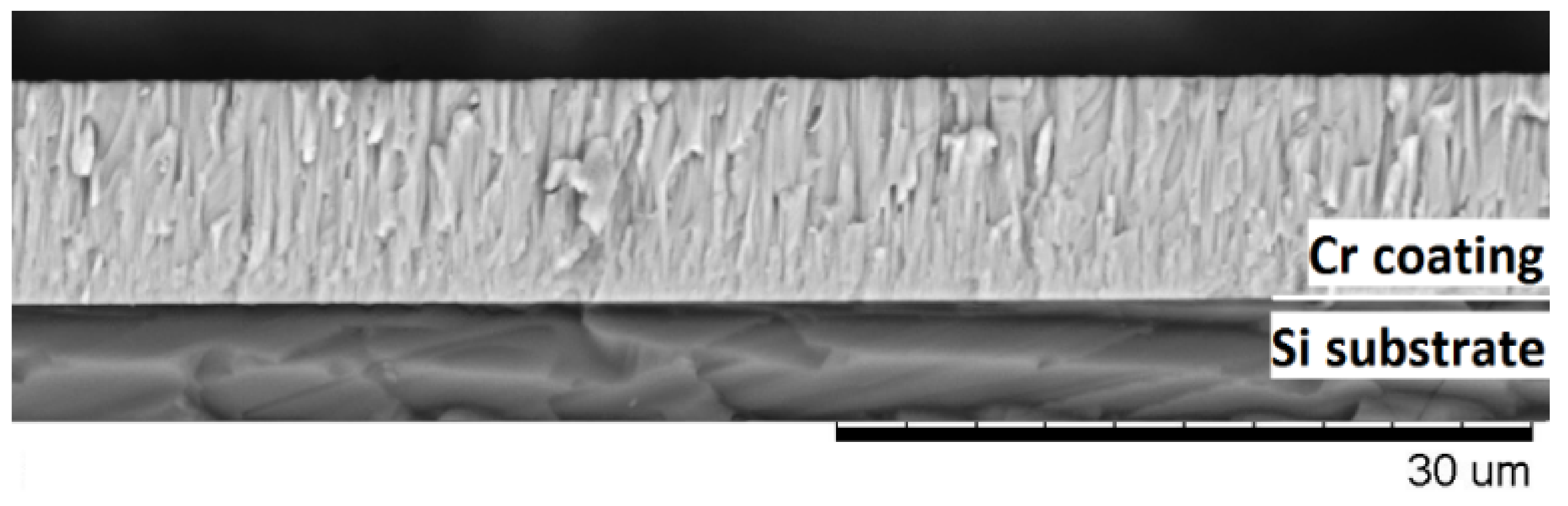
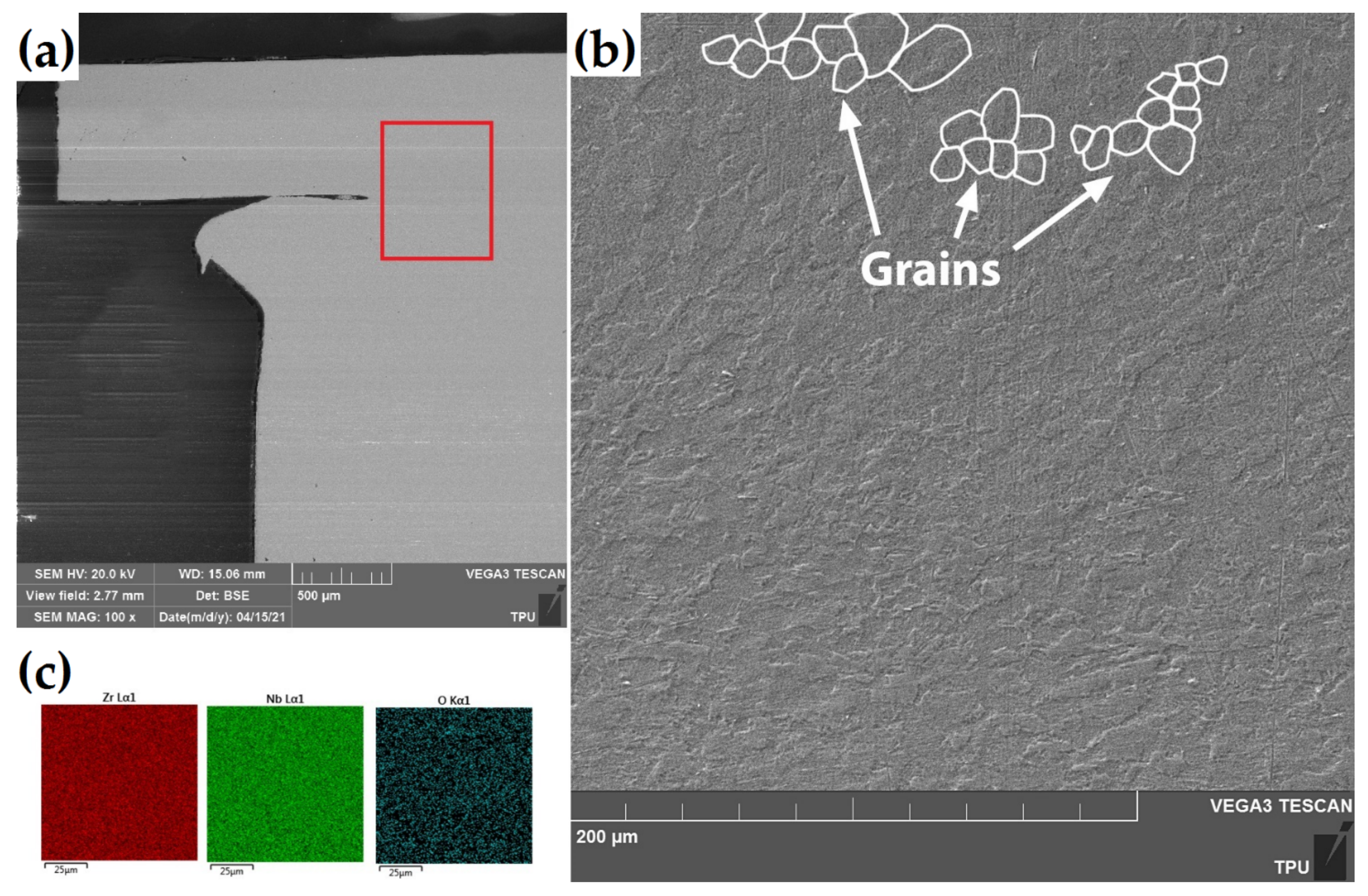
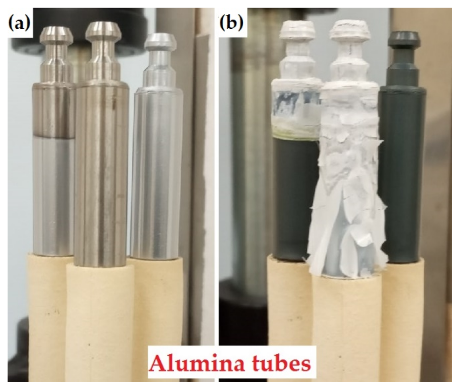
3.1. As-Received Samples
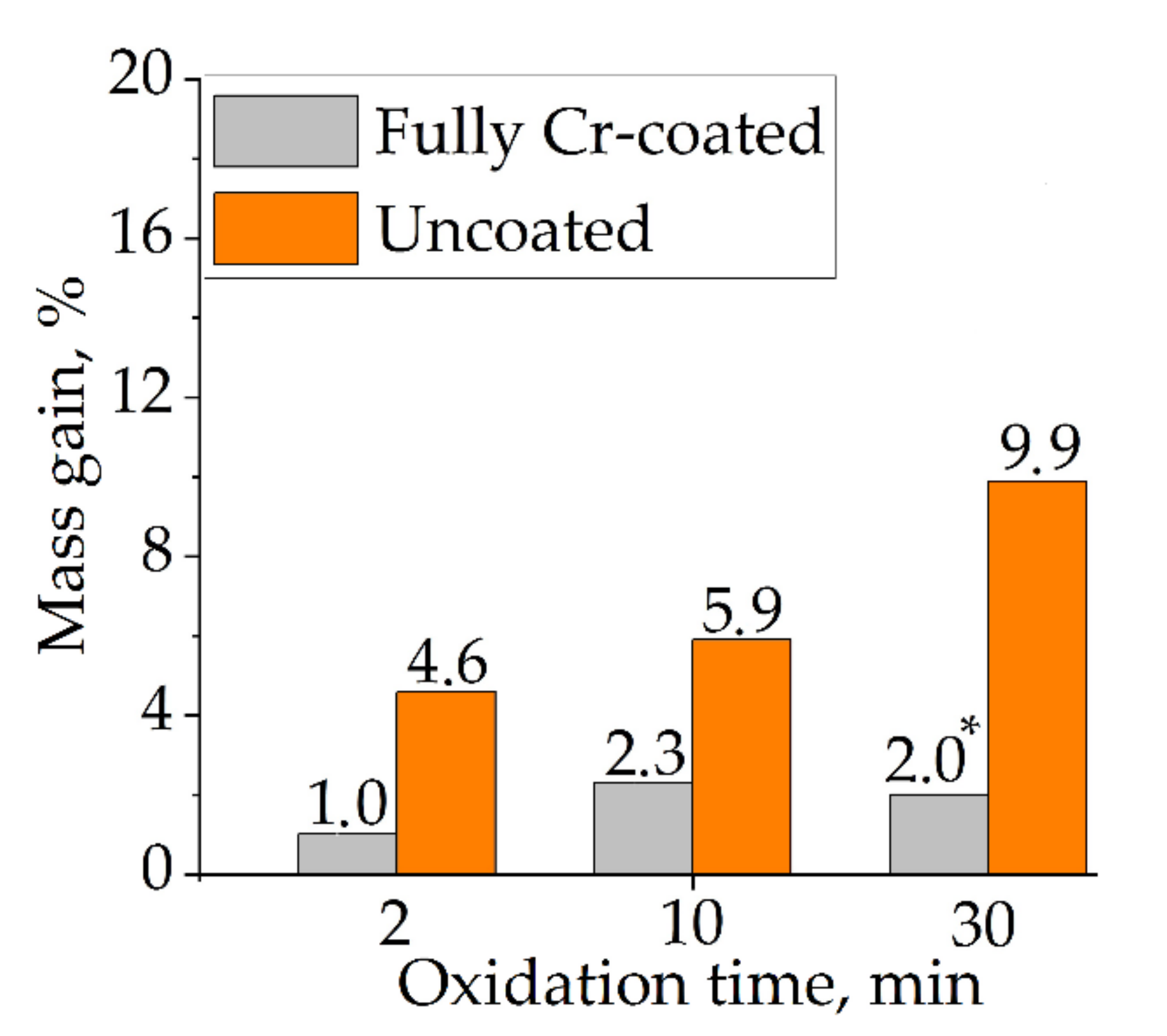
3.2. Weight Gain Measurements
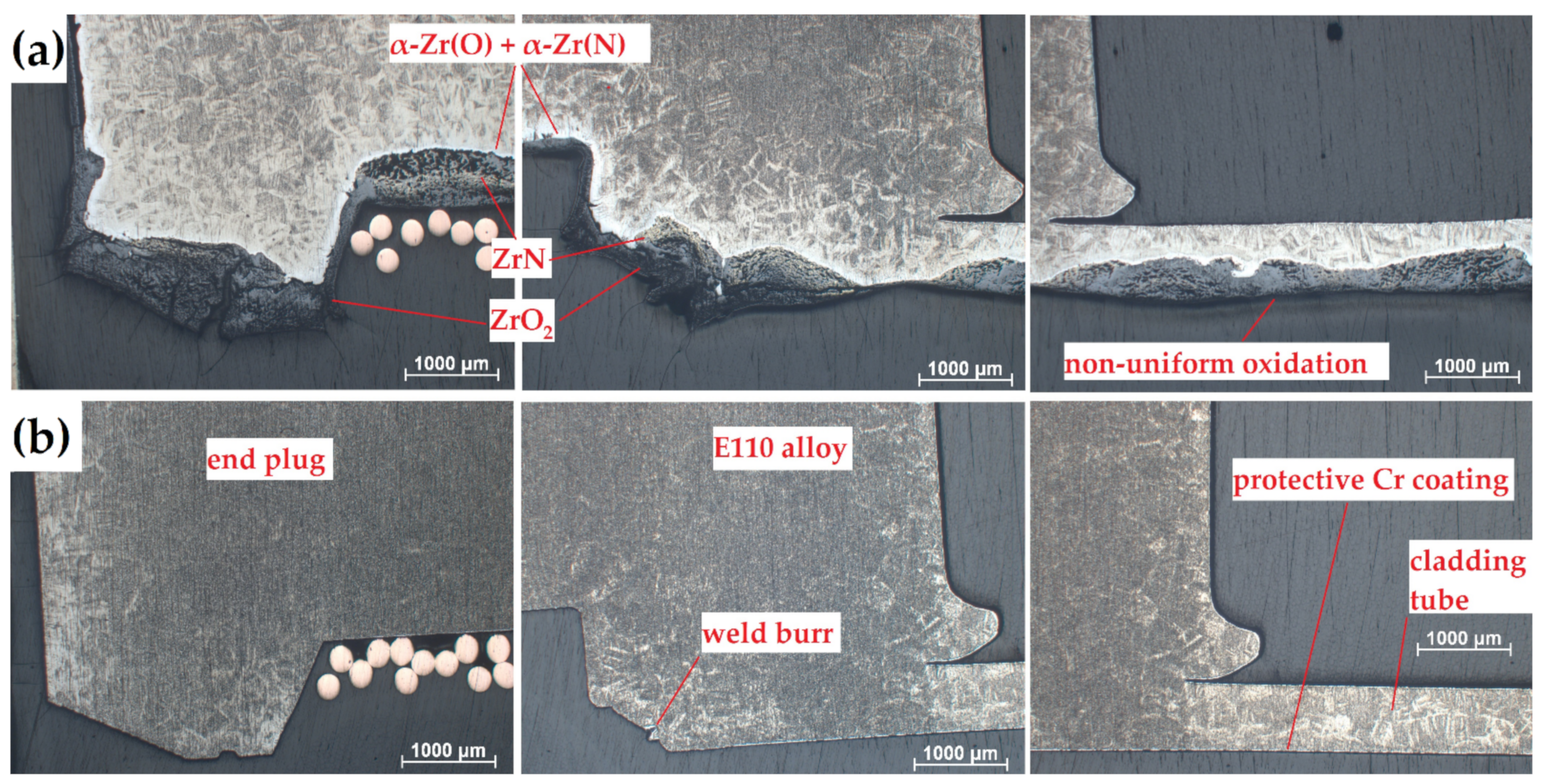
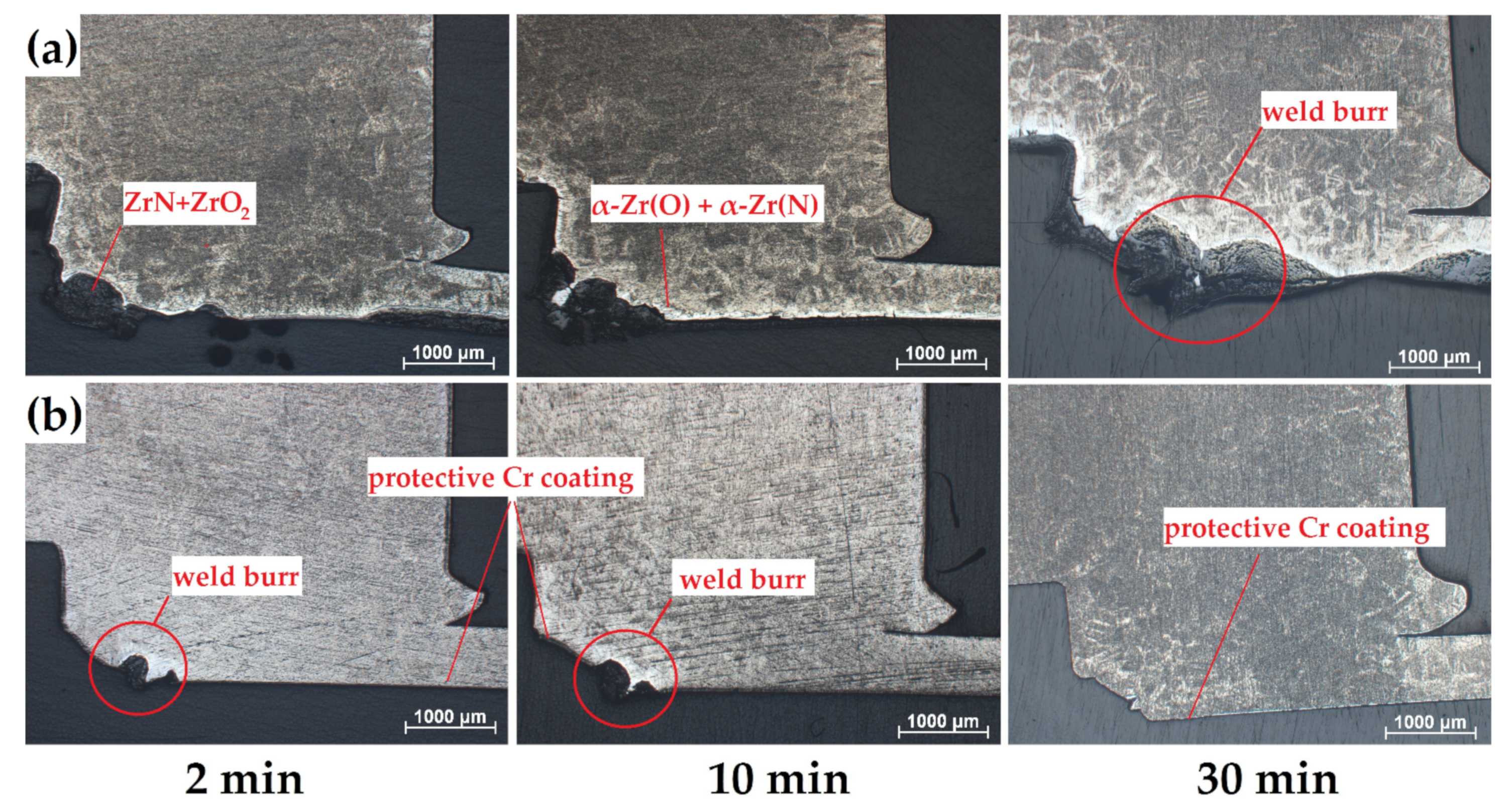
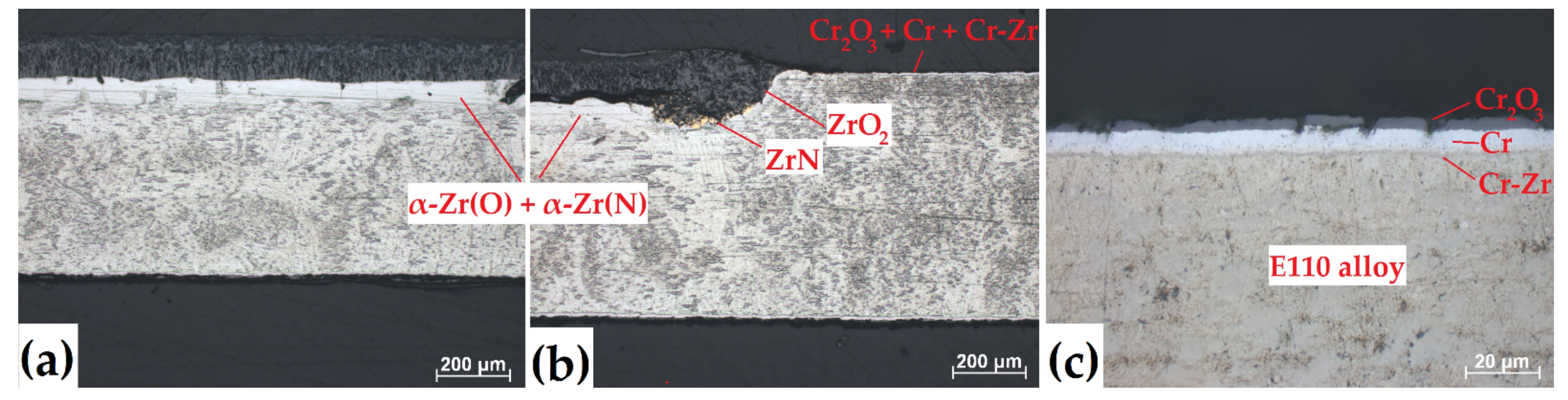
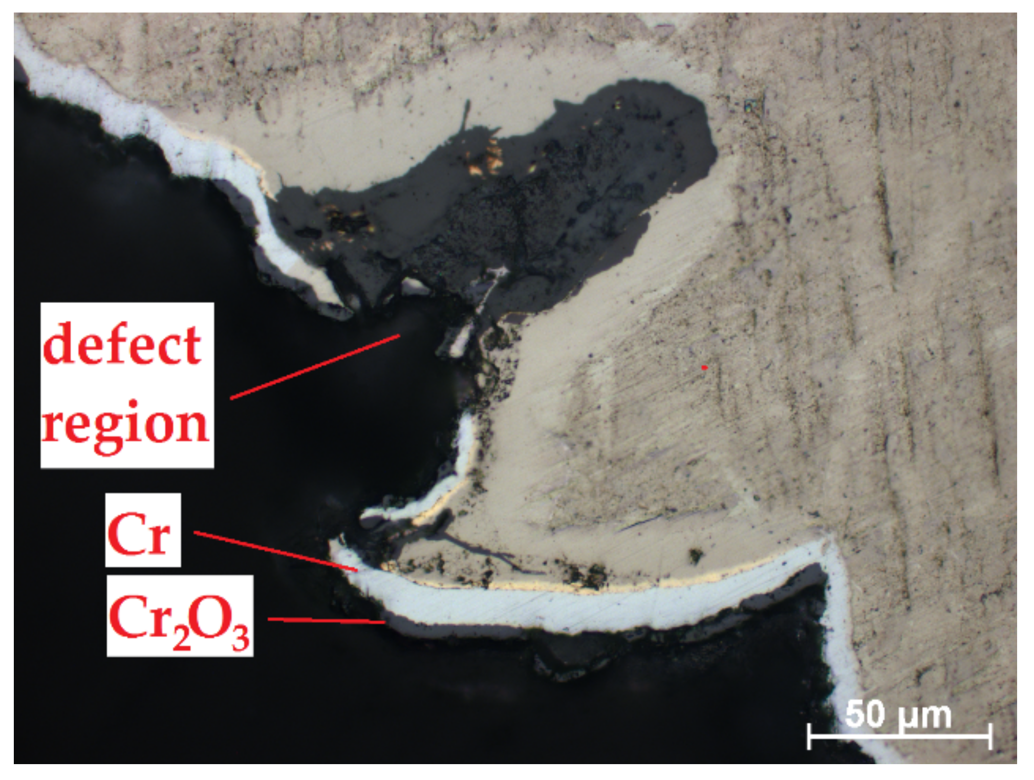
3.3. Cross-Section Microstructure of the Samples
3.4. Elemental Composition of the Samples
3.5. Hardness Distributions
4. Discussion
5. Conclusions
- The RUW welding of E110 alloy does not change oxidation kinetics at high temperatures. The surface non-regularities in the region of weld burr have the most pronounced effect on oxidation rate.
- The Cr coatings can protect RUW-welded samples from oxidation at high temperatures. Partial coating deposition on Zr claddings, especially in the case of uncoated weld, leads to uneven oxidation and material degradation in the area of the end plug/Zr cladding tube. Therefore, the coating deposition on the full surface of nuclear fuel rods after welding of end plugs and cladding seems to be advantageous for development of ATF Zr-based claddings.
- Additional post-treatment procedures like mechanical processing, chemical etching or ion-plasma treatment should be considered for surface smoothing of nuclear fuel rod after RUW welding.
Author Contributions
Funding
Institutional Review Board Statement
Informed Consent Statement
Data Availability Statement
Acknowledgments
Conflicts of Interest
References
- Goldner, F. Development Strategy for advanced LWR Fuels with Enhanced Accident Tolerance; USDOE Office of Nuclear Energy: Washington, DC, USA, 2012. [Google Scholar]
- Tang, C.; Stueber, M.; Seifert, H.J.; Steinbrueck, M. Protective coatings on zirconium-based alloys as accident-tolerant fuel (ATF) claddings. Corros. Rev. 2017, 35, 141–165. [Google Scholar] [CrossRef]
- Kim, H.-G.; Kim, I.-H.; Jung, Y.-I.; Park, D.-J.; Park, J.-Y.; Koo, Y.-H. Adhesion property and high-temperature oxidation behavior of Cr-coated Zircaloy-4 cladding tube prepared by 3D laser coating. J. Nucl. Mater. 2015, 465, 531–539. [Google Scholar] [CrossRef]
- Kuprin, A.S.; Belous, V.A.; Voyevodin, V.N.; Bryk, V.V.; Vasilenko, R.L.; Ovcharenko, V.D. Vacuum-arc chromium-based coatings for protection of zirconium alloys from the high-temperature oxidation in air. J. Nucl. Mater. 2015, 465, 400–406. [Google Scholar] [CrossRef]
- Park, J.H.; Kim, H.-G.; Park, J.; Jung, Y.-I.; Park, D.-J.; Koo, Y.-H. High temperature steam-oxidation behavior of arc ion plated Cr coatings for accident tolerant fuel claddings. Surf. Coat. Technol. 2015, 280, 256–259. [Google Scholar] [CrossRef]
- Sevecek, M.; Gurgen, A.; Seshadri, A.; Che, Y.; Wagih, M.; Phillips, B.; Champagne, V.; Shirvan, K. Development of Cr cold spray-coated fuel cladding with enhanced accident tolerance. Nucl. Eng. Technol. 2018, 50, 229–236. [Google Scholar] [CrossRef]
- Brachet, J.C.; Idarraga-Trujillo, I.; Le Flem, M.; Le Saux, M.; Vandenberghe, V.; Urvoy, S.; Rouesne, E.; Guilbert, T.; Toffolon-Masclet, C.; Tupin, M.; et al. Early studies on Cr-coated zircaloy-4 as enhanced accident tolerant nuclear fuel claddings for light water reactor. J. Nucl. Mater. 2019, 517, 268–285. [Google Scholar] [CrossRef]
- Krejcí, J.; Kabatova, J.; Manoch, F.; Kocí, J.; Cvrcek, L.; Malek, J.; Krum, S.; Sutta, P.; Bublíkova, P.; Halodova, P.; et al. Development and testing of multicomponent fuel cladding with enhanced accidental performance. Nucl. Eng. Tech. 2020, 52, 597–609. [Google Scholar] [CrossRef]
- Brachet, J.C.; Rouesne, E.; Guilbert, T.; Ribis, J.; Le Saux, M.; Nony, G.; Palancher, H.; David, A.; Bischoff, J.; Augereau, J.; et al. High temperature steam oxidation of chromium-coated zirconium-based alloys: Kinetics and process. Corros. Sci. 2020, 167, 108537. [Google Scholar] [CrossRef]
- Yang, J.; Stegmaier, U.; Tang, C.; Steinbruck, M.; Grobe, M.; Wang, S.; Seifert, H.J. High temperature Cr-Zr interaction of two types of Cr-coated Zr alloys in inert gas environment. J. Nucl. Mater. 2021, 547, 152806. [Google Scholar] [CrossRef]
- Mokrushin, A.A. Results of corrosion and thermomechanical tests of ATF-cladding samples. In Proceedings of the 25th International QUENCH Workshop, Karlsruhe Institute of Technology, Karlsruhe, Germany, 22–24 October 2019. [Google Scholar]
- Vandegrift, J.; Pargac, C.J.; Coryell, B.; Butt, D.P.; Jaques, B.J. Oxidation behavior of welded Zry-3, Zry-4, and Zr-1Nb tubes. Nucl. Mater. Energy 2019, 21, 100714. [Google Scholar] [CrossRef]
- Slobodyan, M.S.; Kudiiarov, V.N.; Lider, A.M. Effect of energy parameters of pulsed laser welding of Zr-1%Nb alloy on metal contamination with gases and properties of welds. J. Mater. Processl Technol. 2019, 45, 472–490. [Google Scholar] [CrossRef]
- Slobodyan, M.S.; Pavlov, S.K.; Remnev, G.E. Corrosion and high-temperature steam oxidation of E110 alloy and its laser welds after ion irradiation. Corros. Sci. 2019, 152, 60–74. [Google Scholar] [CrossRef]
- Sakamiti, G.P.; Mota de Siqueira, R.H.; Carvalho, S.M.; Meireles, J.B.; Fernandes de Lima, M.S. Weldability of a zirconium alloy comparing resistance and pulsed laser methods. Nucl. Mat. Energy 2019, 20, 100693. [Google Scholar] [CrossRef]
- Reitz, W.; Rawers, J. Effect of laser surface melted zirconium alloys on microstructure and corrosion resistance. J. Mater. Sci. 1992, 27, 2437–2443. [Google Scholar] [CrossRef]
- Cai, C.; Li, L.; Tao, W. Weld Bead Size, Microstructure and corrosion behavior of zirconium alloys joints welded by pulsed laser spot welding. J. Mater. Eng. Perform. 2016, 25, 3783–3792. [Google Scholar] [CrossRef]
- Cai, C.; Li, L.; Peng, G. Comparative study of oxides formed on fusion zone and base metal of laser welded Zr-1.0Sn-1.0Nb-0.1Fe alloy. J. Mater. Eng. Perform. 2019, 28, 1161–1172. [Google Scholar] [CrossRef]
- Huang, K.-Y.; Tsai, C.-H. The effect of heat treatment on the microstructure and the corrosion resistance of Zircaloy-4 in 450 °C steam. J. Nucl. Mater. 1985, 136, 16–29. [Google Scholar] [CrossRef]
- Goncharov, G.B.; Grabin, V.F.; Korol, A.M.; Adeeva, L.I. Structure and properties of welded joints in laser and arc welding Zr-2.5% Nb alloy. J. Weld. Inter. 2009, 7, 798–801. [Google Scholar] [CrossRef]
- Semenov, A.N.; Plyshevskii, M.I.; Melyukov, V.V. Properties of welded joints from alloy Zr-2.5%Nb after electron-beam local thermocycling. Met. Sci. Heat. Treat. 2014, 55, 670–674. [Google Scholar] [CrossRef]
- Wan, Q.; Baib, X.; Zhanga, X. Impact of high dose krypton ion irradiation on corrosion behavior of laser beam welded zircaloy-4. Mater Res. Bull. 2006, 41, 387–395. [Google Scholar] [CrossRef]
- Semenov, A.N.; Plyshevskii, M.I.; Gordo, V.P.; Rassoshkina, N.S.; Melyukov, V.V.; Korepanov, A.G. Optimization of the heating source in electron beam welding of zirconium pipes. J. Weld. Inter. 2013, 27, 300–303. [Google Scholar] [CrossRef]
- Gnedenkov, A.S.; Sinebryukhov, S.L.; Mashtalyar, D.V.; Vyaliy, I.E.; Egorkin, V.S.; Gnedenkov, S.V. Corrosion of the welded aluminium alloy in 0.5 M NaCl solution. Part 2: Coating protection. Materials 2018, 11, 2177. [Google Scholar] [CrossRef]
- Prasad Rao, K.; Janaki Ram, G.D.; Stucker, B.E. Improvement in corrosion resistance of friction stir welded aluminum alloys with micro arc oxidation coatings. Scr. Mater. 2008, 58, 998–1001. [Google Scholar] [CrossRef]
- Aliasghari, S.; Rogov, A.; Skeldon, P.; Zhou, X.; Yerokhin, A.; Aliabadi, A.; Ghorbani, M. Plasma electrolytic oxidation and corrosion protection of friction stir welded AZ31B magnesium alloy-titanium joints. Surf. Coat. Technol. 2020, 393, 125838. [Google Scholar] [CrossRef]
- Sidelev, D.V.; Kashkarov, E.B.; Syrtanov, M.S.; Krivobokov, V.P. Nickel-chromium (Ni-Cr) coatings deposited by magnetron sputtering for accident tolerant nuclear fuel claddings. Surf. Coat. Technol. 2019, 369, 69–78. [Google Scholar] [CrossRef]
- Kashkarov, E.; Sidelev, D.; Syrtanov, M.; Tang, C.; Steinbrück, M. Oxidation kinetics of Cr-coated zirconium alloy: Effect of coating thickness and microstructure. Corros. Sci. 2020, 175, 108883. [Google Scholar] [CrossRef]
- Zhang, B.; Li, X.; Wang, T.; Wang, X. Microstructure and corrosion behavior of Zr-702 joined by electron beam welding. Vacuum 2015, 121, 159–165. [Google Scholar] [CrossRef]
- Steinbrueck, M.; Silva, F.O.; Grosse, M. Oxidation of Zircaloy-4 in steam-nitrogen mixtures at 600–1200 °C. J. Nucl. Mater. 2017, 490, 226–237. [Google Scholar] [CrossRef]
- Duriez, C.; Dupont, T.; Schmet, B.; Enoch, F. Zircaloy-4 and M5 high temperature oxidation and nitriding in air. J. Nucl. Mater. 2008, 380, 30–45. [Google Scholar] [CrossRef]
- Xiao, W.; Chen, H.; Liu, X.; Tang, D.; Deng, X.; Zou, S.; Ren, Y.; Zhou, X.; Lei, M. Thermal shock resistance of TiN-, Cr-, and TiN/Cr-coated zirconium alloy. J. Nucl. Mat. 2019, 526, 151777. [Google Scholar] [CrossRef]
- Chen, Q.; Xiang, Y.; Li, Z.; He, H.; Zhong, Y.; Zhu, C.; Liu, N.; Yang, Y.; Liao, J.; Chang, H.; et al. Microstructure evolution and adhesion properties of thick Cr coatings under different thermal shock temperatures. Surf. Coat. Technol. 2021, 417, 127224. [Google Scholar] [CrossRef]
- Yang, H.L.; Matsukawa, Y.; Kano, S.; Duan, Z.G.; Murakami, K.; Abe, H. Investigation on microstructural evolution and hardening mechanism in dilute Zr-Nb binary alloys. J. Nucl. Mater. 2016, 481, 117–124. [Google Scholar] [CrossRef]
- Kearns, J. The Use of Microhardness in the Determination of the Diffusivity of Oxygen in Alpha Zirconium; USDOC Office of Technical Services: Washington DC, USA, 1962. [Google Scholar]
- Kashkarov, E.B.; Sidelev, D.V.; Rombaeva, M.; Syrtanov, M.S.; Bleykher, G.A. Chromium coatings deposited by cooled and hot target magnetron sputtering for accident tolerant nuclear fuel claddings. Surf. Coat. Technol. 2020, 389, 125618. [Google Scholar] [CrossRef]
- Yeom, H.; Maier, B.; Johnson, G.; Dabney, T.; Lenling, M.; Sridharan, K. High temperature oxidation and microstructural evolution of cold spray chromium coatings on Zircaloy-4 in steam environments. J. Nucl. Mater. 2019, 526, 151737. [Google Scholar] [CrossRef]
- Krejčí, J.; Ševeček, M.; Kabátová, J.; Manoch, F.; Kočí, J.; Cvrček, L.; Málek, J.; Krum, S.; Šutta, P.; Bublíková, P. Experimental behavior of chromium-based coatings. In Proceedings of the TopFuel 2018, Prague, Czech Republic, 30 September–4 October 2018; Available online: https://www.researchgate.net/publication/328066345 (accessed on 8 May 2021).
- Kashkarov, E.; Afornu, B.; Sidelev, D.; Krinitcyn, M.; Gouws, V.; Lider, A. Recent advances in protective coatings for accident tolerant Zr-based fuel claddings. Coatings 2021, 11, 557. [Google Scholar] [CrossRef]
- Michau, A.; Ougier, M.; Maskrot, H.; Brachet, J.-C.; Guilbert, T.; Palancher, H.; Bischoff, J.; Pouillier, E. Interlayers for Cr-coated nuclear fuel claddings: Preliminary study of Mo. Proceedings of NuMat 2020, Ghent, Belgium, 26–29 October 2020. [Google Scholar] [CrossRef]
- Kalin, B.A.; Volkov, N.V.; Valikov, R.A.; Yashin, A.S. Effect of ion polishing on corrosion resistance of the cladding of fuel elements from E110 alloy in the steam water environment. Inorg. Mat. Appl. Res. 2017, 8, 364–369. [Google Scholar] [CrossRef]


| Q, W/cm2 | P, Pa | t, min | Usub, V | jsub, mA/cm2 | Tsub, °C | h, μm |
|---|---|---|---|---|---|---|
| 39.1 | 0.25 | 192 | −100 | 20 | <390 | 9.8 ± 0.4 |
| Title | Uncoated | Partially Cr-Coated | Fully Cr-Coated |
|---|---|---|---|
| 2 min oxidation |  |  |  |
| 10 min oxidation |  |  | 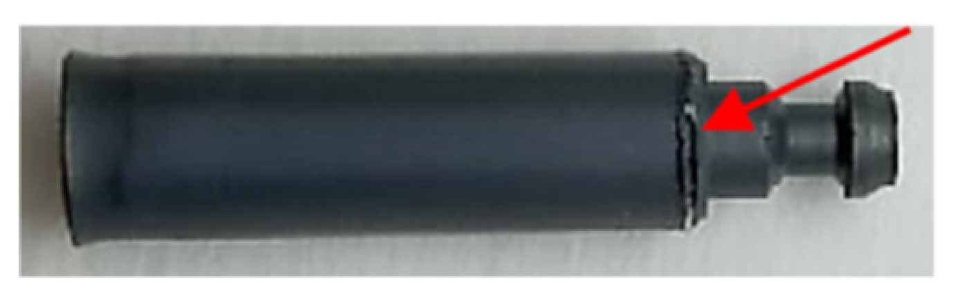 |
| 30 min oxidation | 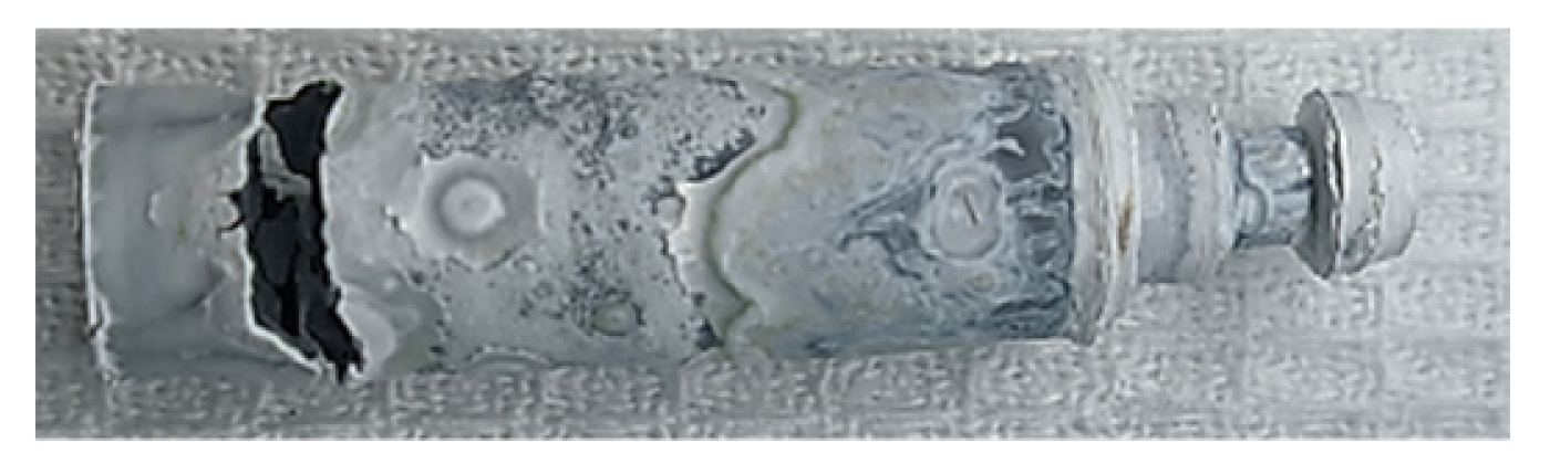 | 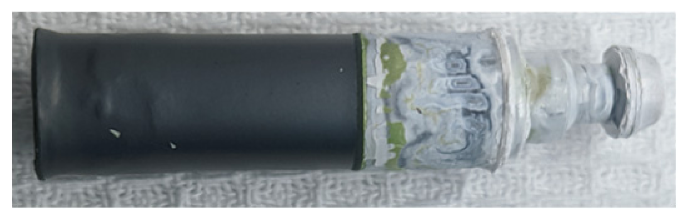 | 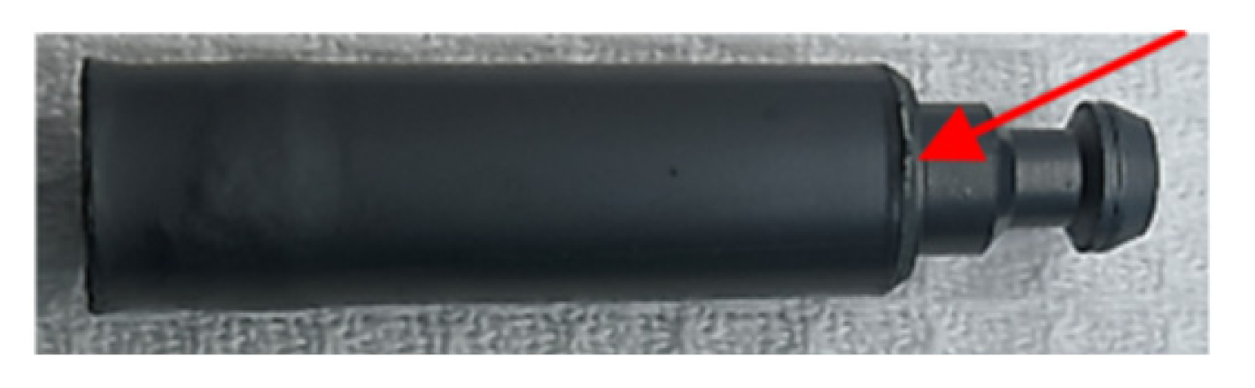 |
Publisher’s Note: MDPI stays neutral with regard to jurisdictional claims in published maps and institutional affiliations. |
© 2021 by the authors. Licensee MDPI, Basel, Switzerland. This article is an open access article distributed under the terms and conditions of the Creative Commons Attribution (CC BY) license (https://creativecommons.org/licenses/by/4.0/).
Share and Cite
Sidelev, D.; Ruchkin, S.; Kashkarov, E. High-Temperature Oxidation of Cr-Coated Resistance Upset Welds Made from E110 Alloy. Coatings 2021, 11, 577. https://doi.org/10.3390/coatings11050577
Sidelev D, Ruchkin S, Kashkarov E. High-Temperature Oxidation of Cr-Coated Resistance Upset Welds Made from E110 Alloy. Coatings. 2021; 11(5):577. https://doi.org/10.3390/coatings11050577
Chicago/Turabian StyleSidelev, Dmitrii, Sergey Ruchkin, and Egor Kashkarov. 2021. "High-Temperature Oxidation of Cr-Coated Resistance Upset Welds Made from E110 Alloy" Coatings 11, no. 5: 577. https://doi.org/10.3390/coatings11050577
APA StyleSidelev, D., Ruchkin, S., & Kashkarov, E. (2021). High-Temperature Oxidation of Cr-Coated Resistance Upset Welds Made from E110 Alloy. Coatings, 11(5), 577. https://doi.org/10.3390/coatings11050577