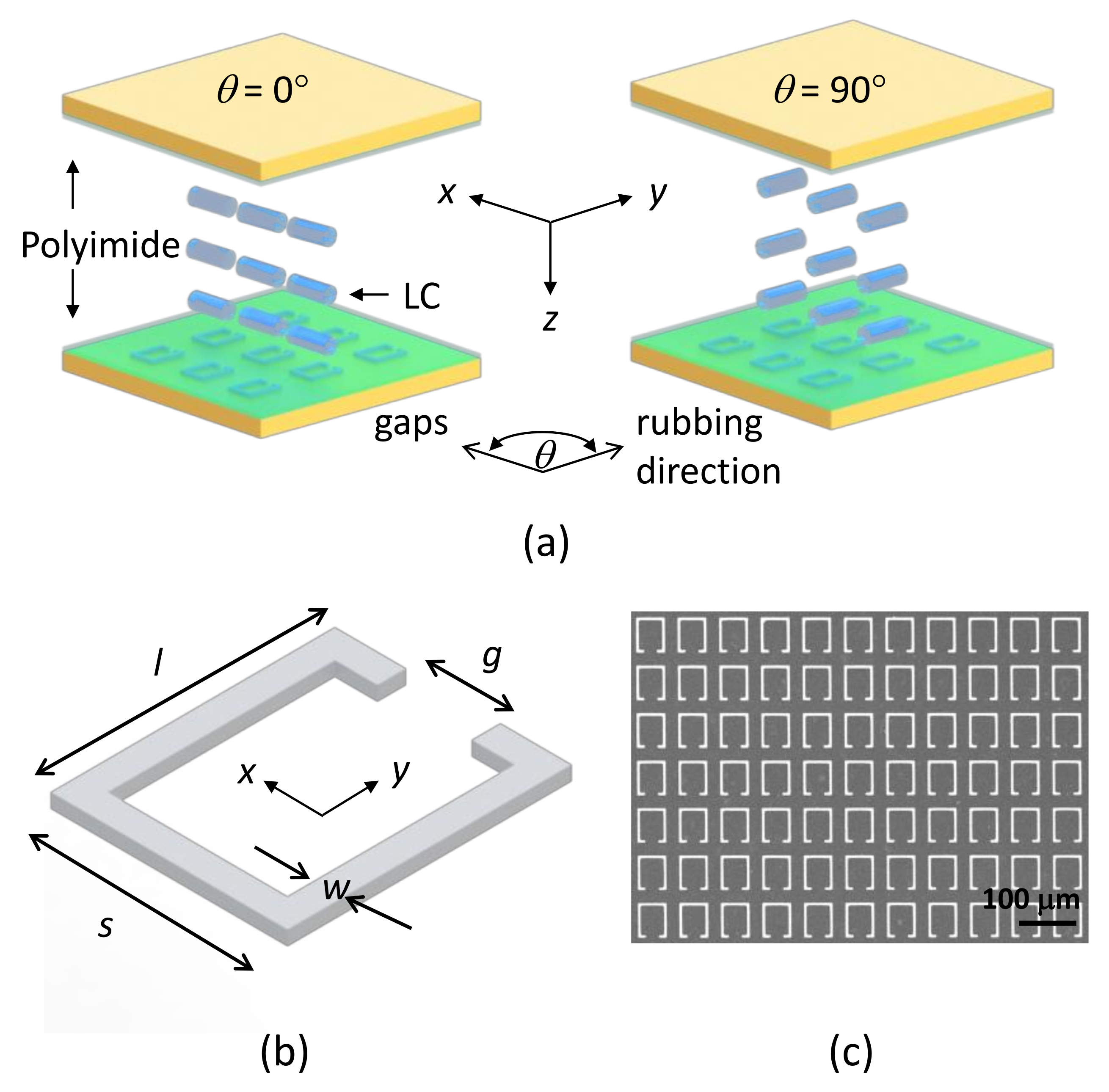
3. Results and Discussion
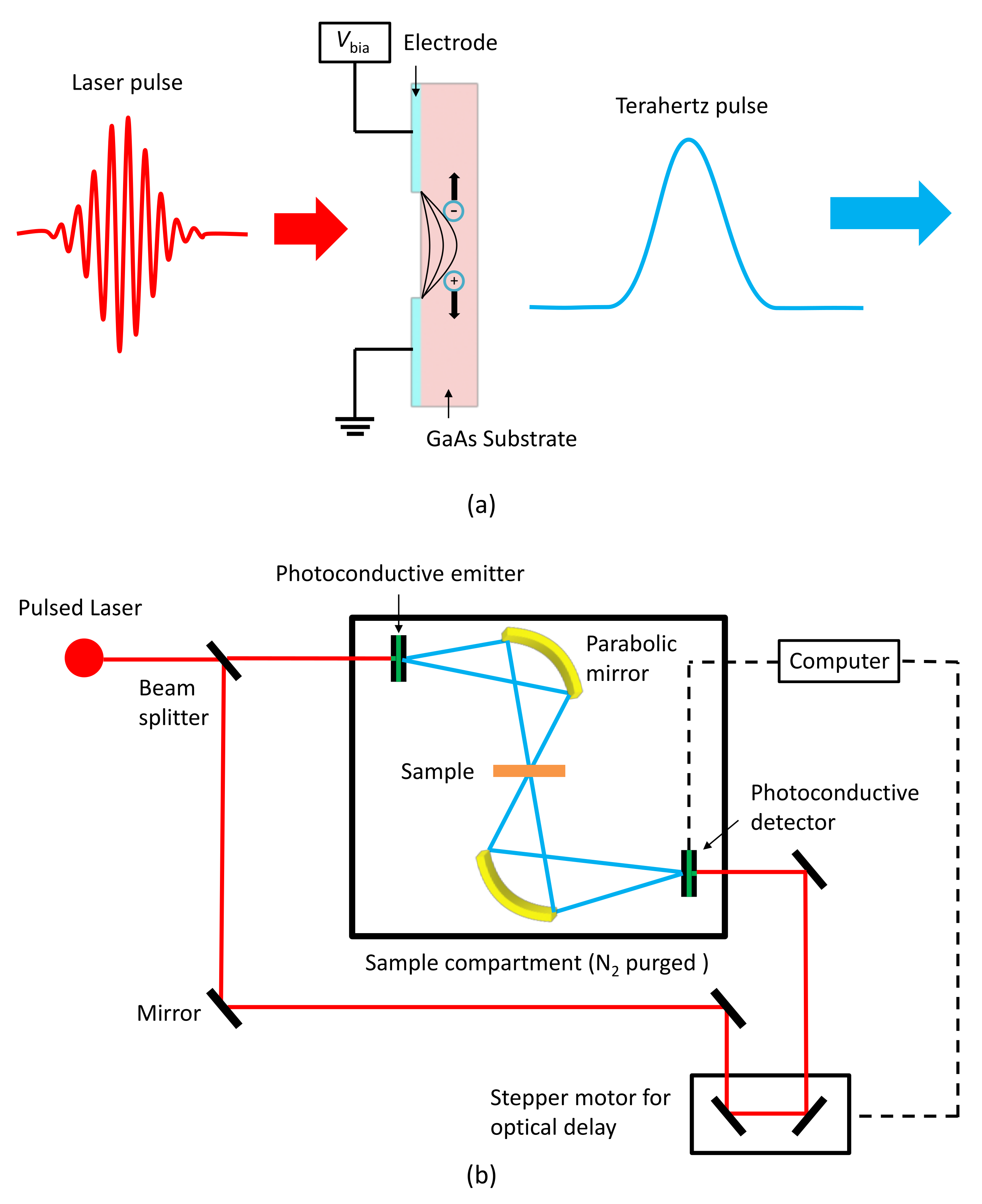
Before the polyimide-coated metamaterials are deposited with the LC layers, their terahertz spectra are measured using a commercial terahertz spectrometer (TPS 3000, TeraView, Cambridge, UK) in transmission mode. The spectrometer has frequency resolutions of 1 GHz, 3 GHz, and 6 GHz. A frequency resolution of 3 GHz is used in the measurement because spectra are not smooth at a frequency resolution of 1 GHz. The polarized direction of incident terahertz waves is set parallel to the
x axis of
Figure 1a, and the chamber in the spectrometer is filled with nitrogen gas to prevent terahertz waves from absorbing moisture.
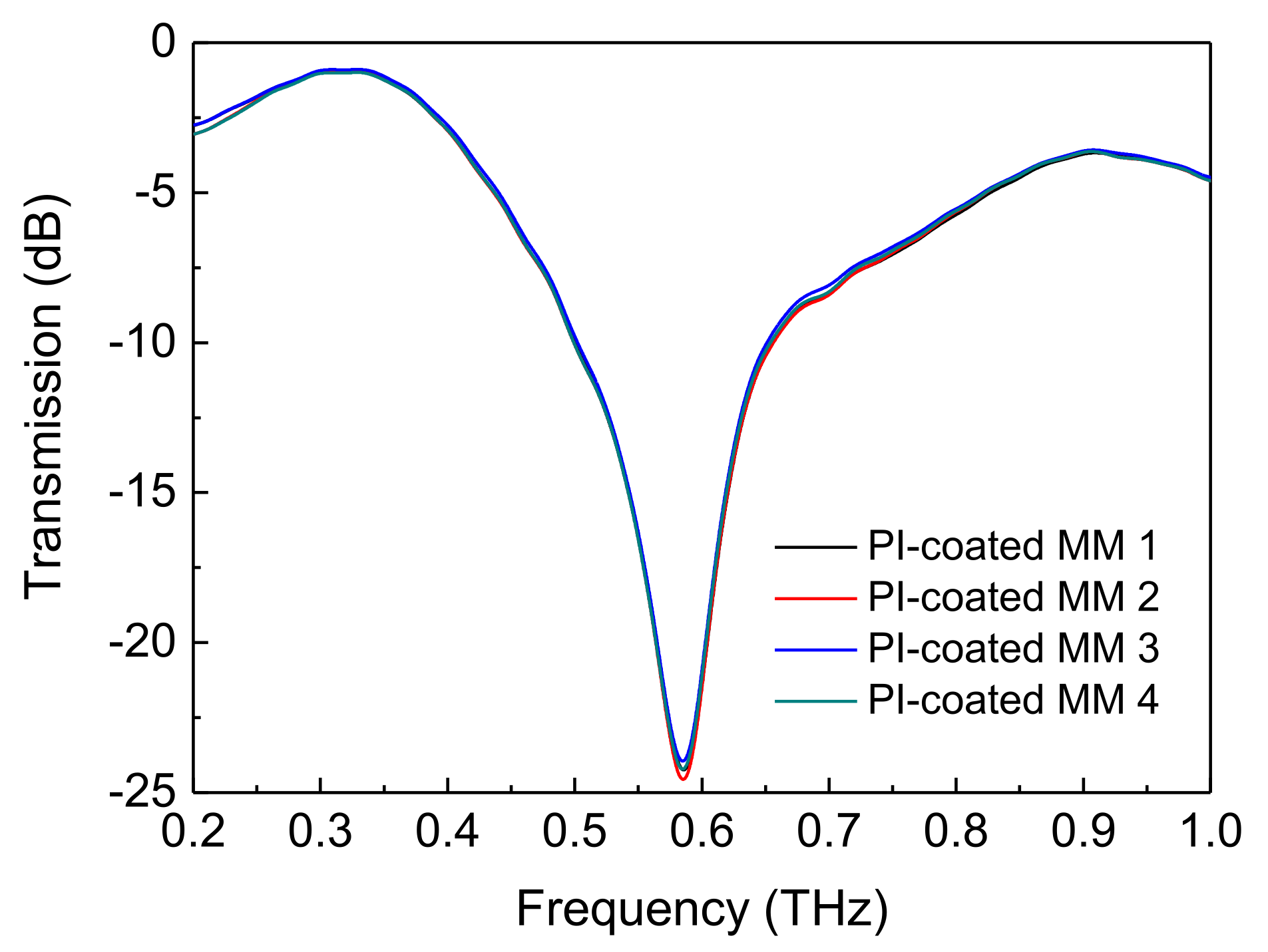
Figure 3 displays the experimental terahertz spectra of any four of the polyimide-coated metamaterials. The four polyimide-coated metamaterials have transmission peaks in their terahertz spectra owing to the absorption of their electromagnetic resonance. The four polyimide-coated metamaterials have the same resonance frequency at 0.588 THz, and they have similar resonance spectra. Therefore, the polyimide-coated metamaterials can be used to study the effect of the thicknesses of the LC layers on the shift of the resonance frequencies of the metamaterials.
A simulation is performed using a software based on finite element method to verify the experimental spectra of the polyimide-coated metamaterials. A simulated SRR has the same geometrical dimensions as the SRR of
Figure 1b, and is deposited on a 188 µm thick PET substrate with an area of 70 µm × 80 µm. A 600 nm thick polyimide film is coated on the simulated SRR. A periodical boundary condition is set in the simulation, and the conductivity of silver in the simulated SRR is 6.30 × 10
7 S/m. The refractive index of the PET substrate (polyimide film) is 1.73 (1.10) in the simulation, and was obtained from its terahertz time-domain spectrum. Jin et. al. present that PET is weakly dispersive in a frequency range between 0.5 THz and 0.6 THz [
18]. We also obtained this result by measuring the terahertz time-domain spectrum of the PET substrate via the spectrometer (data not shown herein). Tao et. al. display that polyimide is weakly dispersive in a frequency range between 0.2 THz and 2.5 THz [
19]. We also obtained this result by measuring the terahertz time-domain spectrum of the polyimide film via the spectrometer (data not shown herein).
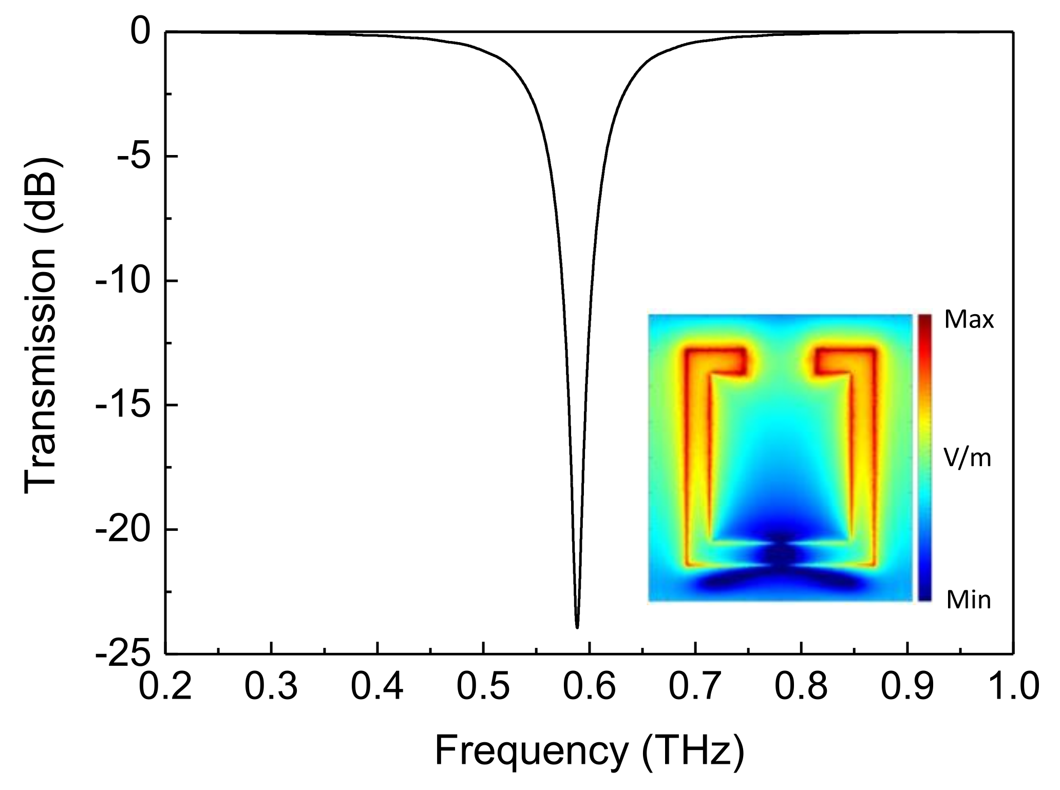
Figure 4 displays the simulated spectrum of the polyimide-coated metamaterials. These metamaterials have a simulated peak at 0.588 THz. Therefore, the peak frequency of the simulated spectrum of
Figure 4 verifies that of the experimental spectra of
Figure 3. The inset in
Figure 4 presents the near-field distribution of the PET substrate with the simulated polyimide-coated SRR at 0.588 THz. The near field of this SRR exhibits the maximum strength at its gap. This result depicts that the electromagnetic resonance of the polyimide-coated metamaterials is an inductive-capacitive mode at 0.588 THz.
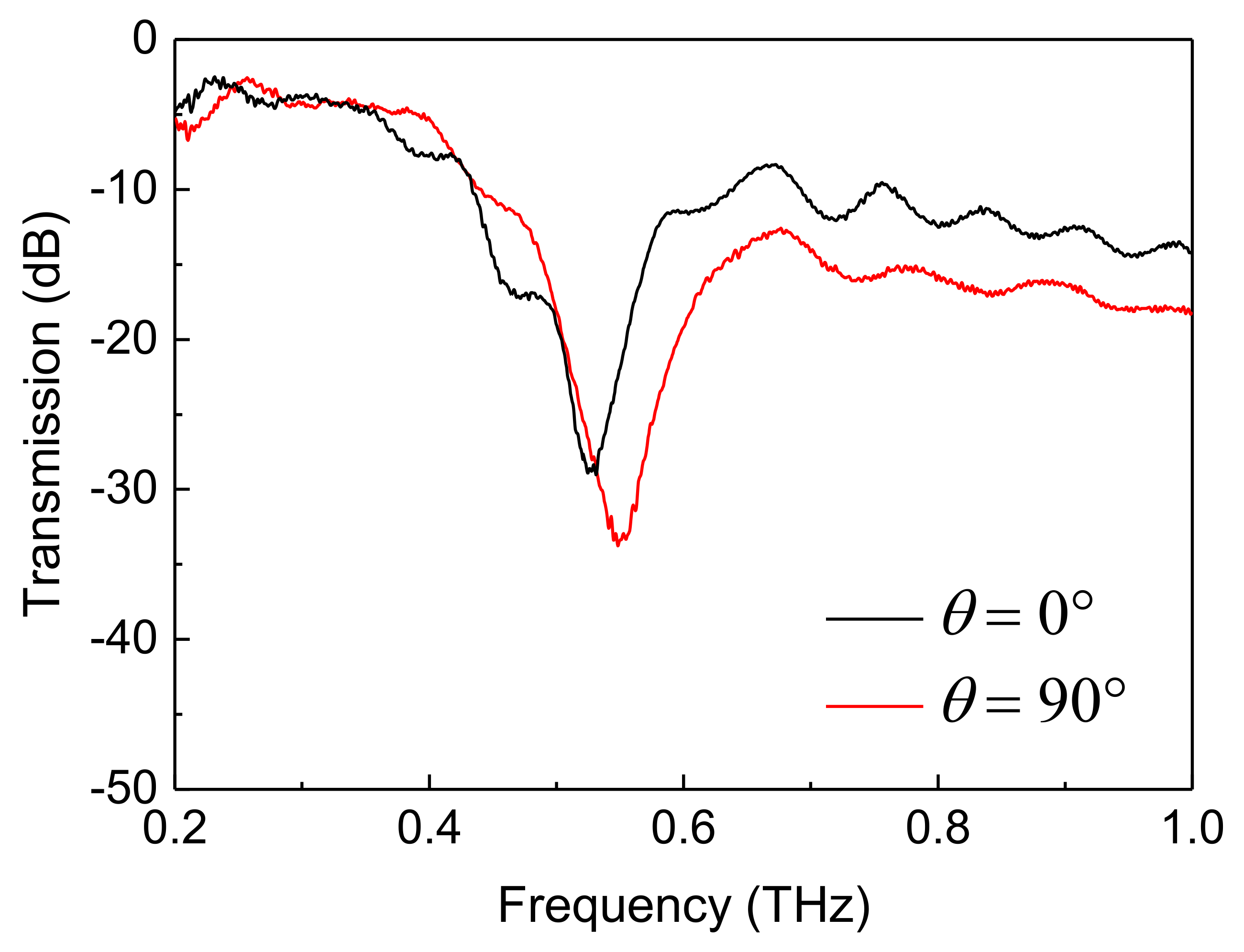
Figure 5 presents the terahertz spectra of the metamaterial-imbedded cells with an LC thickness of 710 µm in a spectral resolution of 1 GHz. Because these spectra are not smooth, it is very difficult to determine the resonance frequencies of the metamaterials in the cells at
θ = 0° and 90°. Therefore, a spectral resolution of 3 GHz is used in this work.
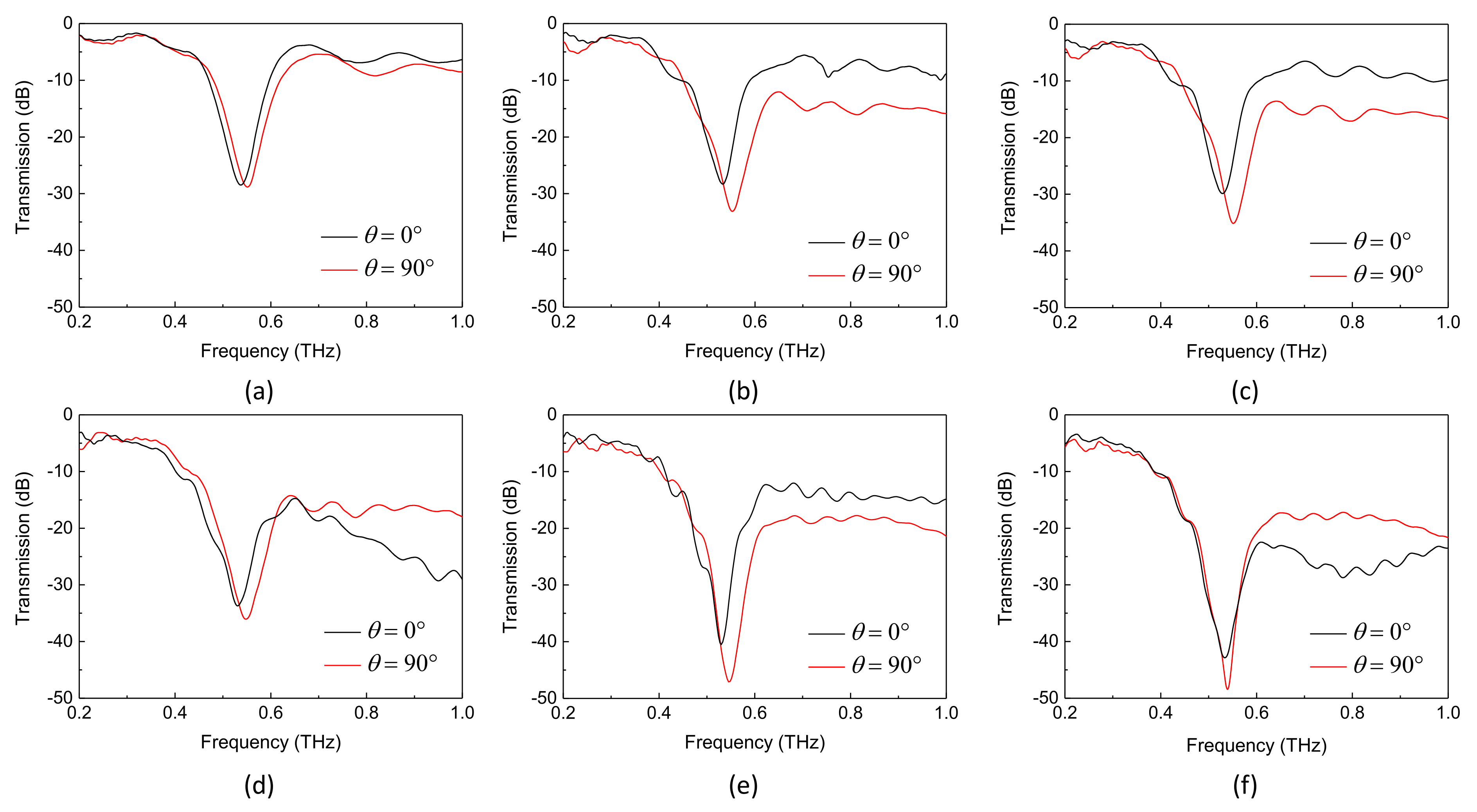
Figure 6a–d present the terahertz spectra of the metamaterial-imbedded cells with LC thicknesses
d of 310 µm, 500 µm, 710 µm, 1000 µm, 1300 µm, and 1487 µm, respectively, at
θ = 0° and 90°. The resonance frequencies of the metamaterials in two cells of each LC thickness are sensitive to the rubbing directions of the polyimide layers because the frequencies are different at
θ = 0° and 90°. This result can be explained using the inductor-capacitor circuit model of a SRR. The resonance frequency
f of the SRR is given by the following [
17]:
where
L is an inductance of the inductor,
C is a capacitance of the capacitor, and
n is the refractive index of a dielectric layer deposited on the SRR. Equation (1) reveals that
f is in inverse proportion to
n. In addition, incident terahertz waves “experience” the different refractive indices of the LC in two metamaterial-embedded cells of each LC thickness because the polarized direction of the waves makes angles of 0° and 90° with respect to the rubbing directions of the polyimide layers. Therefore, the resonance frequencies of the metamaterials in two cells of each LC thickness are sensitive to the rubbing directions of the polyimide layers.
The resonance frequencies of the metamaterials in the twelve cells are named
f0° and
f90° at
θ = 0° and 90°, respectively. Two metamaterial-embedded cells of each LC thickness have a frequency shifting range of Δ
f =
f90° −
f0°.
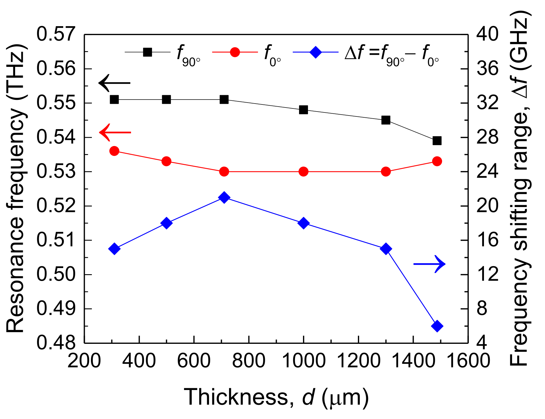
Figure 7 presents the dependences of
f0°,
f90°, and Δ
f on
d = 310 µm, 500 µm, 710 µm, 1000 µm, 1300 µm, and 1487 µm.
f90° equals 0.551 THz, 0.551 THz, 0.551 THz, 0.548 THz, 0.545 THz, and 0.539 THz at
d = 310 µm, 500 μm, 710 µm, 1000 µm, 1300 µm, and 1487 µm, respectively. Therefore,
f90° has the maximum shift of 12 GHz.
f0° equals 0.536 THz, 0.533 THz, 0.530 THz, 0.530 THz, 0.530 THz, and 0.533 THz at
d = 310 µm, 500 µm, 710 µm, 1000 µm, 1300 µm, and 1487 µm, respectively. Therefore,
f0° has the maximum shift of 6 GHz. The maximum shifts of
f90° and
f0° exceed the resolution (3 GHz) of the spectrometer, so the results are reliable.
f90° decreases as
d increases from 310 µm to 1487 µm. The decrease in
f90° arises from two reasons. One of the reasons is the effect of the wavelengths of incident terahertz waves on the refractive indices of the LC, which is named the wavelength effect herein. The other reason is the effect of the alignment of the polyimide films on the refractive indices of the LC, which is named the alignment effect herein.
The wavelength effect of the cells at
θ = 90° is discussed as follows. As
d equals 310 µm, the metamaterial has a resonance wavelength of 3 × 10
8/0.551 THz ≈ 544 µm in the cell at
θ = 90°. Because the thickness (310 µm) of the LC layer is smaller than the resonance wavelength (544 µm) of the metamaterial, the LC layer is too thin to interact with the incident terahertz waves significantly [
15,
16]. As
d is increased to 1487 µm, the metamaterial has a resonance wavelength of 3 × 10
8/0.539 THz ≈ 557 µm in the cell at
θ = 90°. Because the thickness (1487 µm) of the LC layer exceeds the resonance wavelength (557 µm) of the metamaterial, the LC layer interacts with the terahertz waves significantly [
15,
16]. The interaction between the thick LC layer and the incident terahertz waves is more significant than that between the thin LC layer and the waves. This fact reveals that the terahertz waves with a polarized direction parallel to the
x axis of
Figure 1a “experience” a larger ordinary refractive index
no in the thick LC layer than in the thin LC layer as the cells are at
θ = 90°. In addition, Equation (1) reveals that
f is in inverse proportion to
n. Therefore, the wavelength effect of the cells at
θ = 90° increases
no as
d increases from 310 µm to 1487 µm, decreasing
f90° at the increase in
d.
The alignment effect of the cells at
θ = 90° is discussed as follows. The alignment layers in a metamaterial-imbedded cell align the nematic domains of the LC layer up to distances from the surfaces of the layers above which they are not aligned. Therefore, the LC layer in the cell has the unaligned domain sandwiched between the two nematic domains. The nematic domains in the metamaterial-imbedded cells have the same thickness owing to the same long-range force of the alignment layers. In addition, the unaligned domain has a larger thickness in a thick LC layer than in a thin LC layer owing to the limited long-range force of the alignment layers. Therefore, the unaligned domains in the LC layers determine the alignment effect of the metamaterial-imbedded cells. The LC molecules have more inhomogeneous orientations in a thick unaligned domain than in a thin unaligned domain, so the LC director makes a smaller angle with respect to the gaps of the SRRs of the metamaterial in a thick LC layer than in a thin LC layer. This fact reveals that the terahertz waves with a polarized direction parallel to the
x axis of
Figure 1a “experience” a larger
no in the thick LC layer than in the thin LC layer. In addition, Equation (1) reveals that
f is in inverse proportion to
n. Therefore, the alignment effect decreases
f90° as
d increases from 310 µm to 1487 µm. The wavelength and alignment effects both increase
no as
d increases from 310 µm to 1487 µm, reducing
f90° at the increase in
d.
f90° are constant at
d = 310 µm, 500 µm, and 710 µm because a difference in actual
f90° between
d = 310 µm and
d = 710 µm is smaller than the frequency resolution (3 GHz) of the spectrometer. A simulation will be performed to verify this explanation.
Figure 7 presents that
f0° decreases and then increases as
d increases from 310 µm to 1487 µm. The change in
f0° arises from the competition between the wavelength and alignment effects in the cells at
θ = 0°. The wavelength effect of the cells at
θ = 0° is discussed as follows. As
d equals 310 µm, the metamaterial has a resonance wavelength of 3 × 10
8/0.536 THz ≈ 560 µm in the cell at
θ = 0°. Because the thickness (310 µm) of the LC layer is smaller than the resonance wavelength (560 µm) of the metamaterial, the LC layer is too thin to interact with the incident terahertz waves significantly [
15,
16]. As
d is increased to 1487 µm, the metamaterial has a resonance wavelength of 3 × 10
8/0.533 THz ≈ 563 µm in the cell at
θ = 0°. Because the thickness (1487 µm) of the LC layer exceeds the resonance wavelength (563 µm) of the metamaterial, the LC layer interacts with the terahertz waves significantly [
15,
16]. The interaction between the thick LC layer and the incident terahertz waves is more significant than that between the thin LC layer and the waves. This fact reveals that the terahertz waves with a polarized direction parallel to the
x axis of
Figure 1a “experience” a larger extraordinary refractive index
ne of the LC in the thick LC layer than in the thin LC layer. In addition, Equation (1) displays that
f is in inverse proportion to
n. Therefore, the wavelength effect of the cells at
θ = 0° increases
ne as
d increases from 310 µm to 1487 µm, decreasing
f0° at the increase in
d.
The alignment effect of the cells at
θ = 0° is discussed as follows. The LC molecules have more inhomogeneous orientations in a thick unaligned domain than in a thin unaligned domain, so the LC director makes a larger angle with respect to the gaps of the SRRs of the metamaterial in a thick LC layer than in a thin LC layer. This fact reveals that the terahertz waves with a polarized direction parallel to the
x axis of
Figure 1a “experience” a smaller
ne in the thick LC layer than in the thin LC layer. In addition, Equation (1) displays that
f is in inverse proportion to
n. Therefore, the alignment effect of the cells at
θ = 0° decreasing
ne as
d increases from 310 µm to 1487 µm, increasing
f0° at the increase in
d.
f0° decreases at an increase in
d from 310 µm to 710 µm because the wavelength effect prevails over the alignment effect.
f0° are constant at
d = 710 µm, 1000 µm, and 1300 µm because a difference in actual
f0° between
d = 710 µm and
d = 1300 µm is smaller than the frequency resolution (3 GHz) of the spectrometer. A simulation will be performed to verify this explanation.
f0° increases at an increase in
d from 1300 µm to 1487 µm because the alignment effect prevails over the wavelength effect. The competition between the wavelength and alignment effects increases
ne and then decreases it as
d increases from 310 µm to 1487 µm. Therefore, the competition between the two effects decreases
f0° and then increases it at the increase in
d.
Figure 7 presents that Δ
f decreases and then increases as
d increases from 310 µm to 1487 µm, and has a maximum of 21 GHz at
d = 710 µm. The competition between the wavelength and alignment effects causes the maximum birefringence of the LC at
d = 710 µm, so the metamaterials have the maximum frequency shifting range at the LC thickness as the cells are at
θ = 0°.
A simulation is performed using the software to verify the experimental results of
Figure 7. A dielectric layer with a refractive index of
n is deposited on the PET substrate with the simulated polyimide-coated SRR (the inset of
Figure 4). As the resonance frequency of this SRR equals that of a metamaterial-imbedded cell with an LC thickness at
θ = 0° (90°),
n equals the extraordinary (ordinary) refractive index
ne (
no) of the LC at the thickness. Therefore, the extraordinary and ordinary refractive indices of the LC are obtained from the experimental resonance frequencies of the metamaterials. The wavelength and alignment effects determine the experimental resonance frequencies of the metamaterials. In addition, Equation (1) reveals that
f is in inverse proportion to
n. Therefore, the wavelength and alignment effects dominate the extraordinary and ordinary refractive indices of the LC. In other words, the effects are incorporated into these indices.
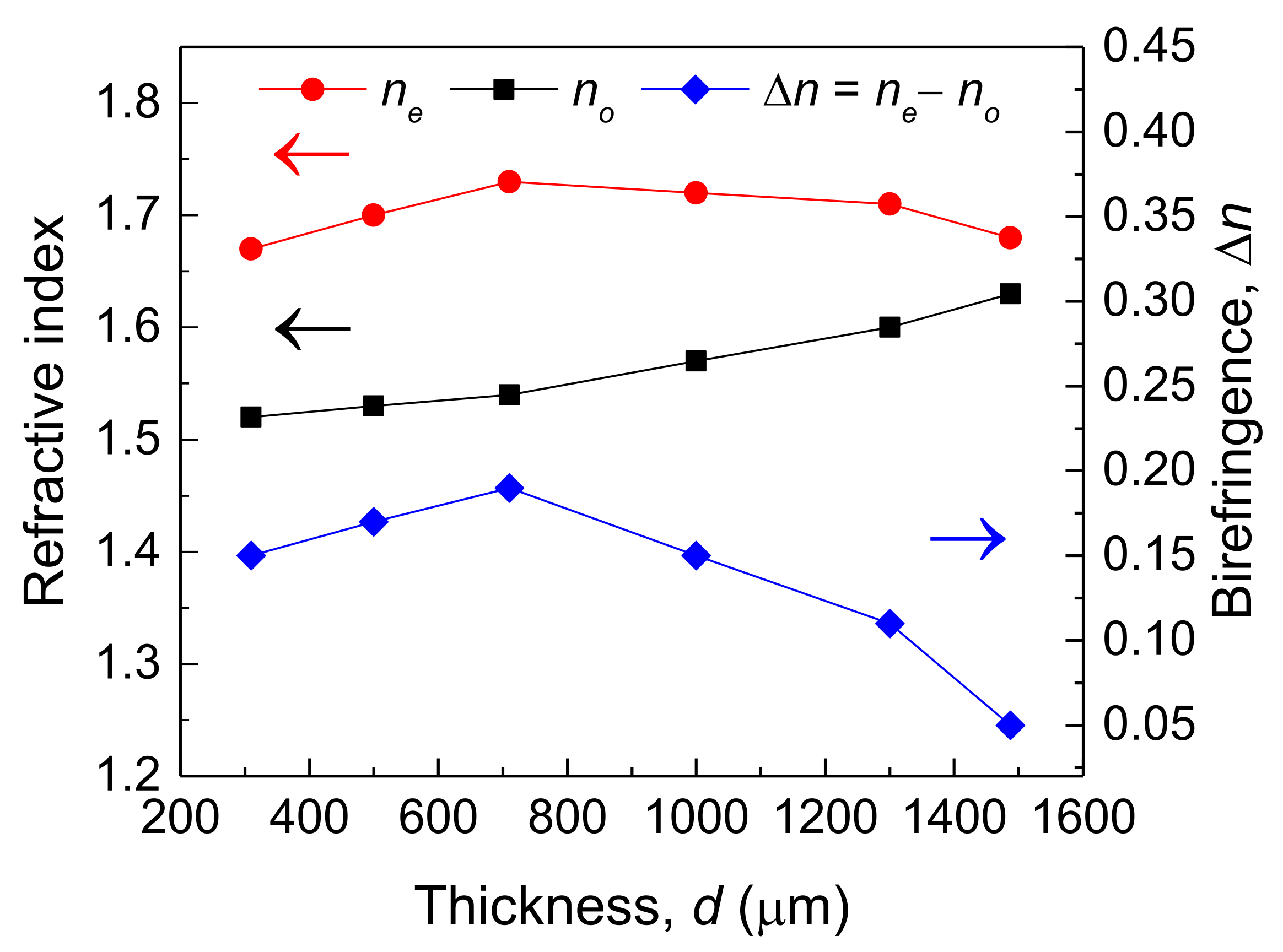
Figure 8 displays the dependences of
ne,
no, and Δ
n on
d = 310 µm, 500 µm, 710 µm, 1000 µm, 1300 µm, and 1487 µm.
no are 1.52, 1.53, 1.54, 1.57, 1.60, and 1.63 at
d = 310 µm, 500 µm, 710 µm, 1000 µm, 1300 µm, and 1487 µm, respectively.
no increases as
d increases from 310 µm to 1487 µm. This result verifies that the wavelength and alignment effects both increase
no as
d increases from 310 µm to 1487 µm. Therefore, the two effects both decrease
f90° at the increase in
d. A difference in
no between
d = 310 µm and
d = 710 µm is merely 0.02, so the shift of the resonance spectra cannot be detected by the spectrometer with a frequency resolution of 3 GHz as
d increases from 310 µm to 710 µm.
ne are 1.67, 1.70, 1.73, 1.72, 1.71, and 1.68 at
d = 310 µm, 500 µm, 710 µm, 1000 µm, 1300 µm, and 1487 µm, respectively.
ne increases and then decreases as
d increases from 310 µm to 1487 µm. This result verifies that the competition between the wavelength and alignment effects increases
ne and then decreases it as
d increases from 310 µm to 1487 µm. Therefore, the competition between the two effects decreases
f0° and then increases it at the increase in
d. A difference in
ne between
d = 710 µm and
d = 1300 µm is merely 0.02, so the shift of the resonance spectra cannot be detected by the spectrometer with a frequency resolution of 3 GHz as
d increases from 710 µm to 1300 µm.
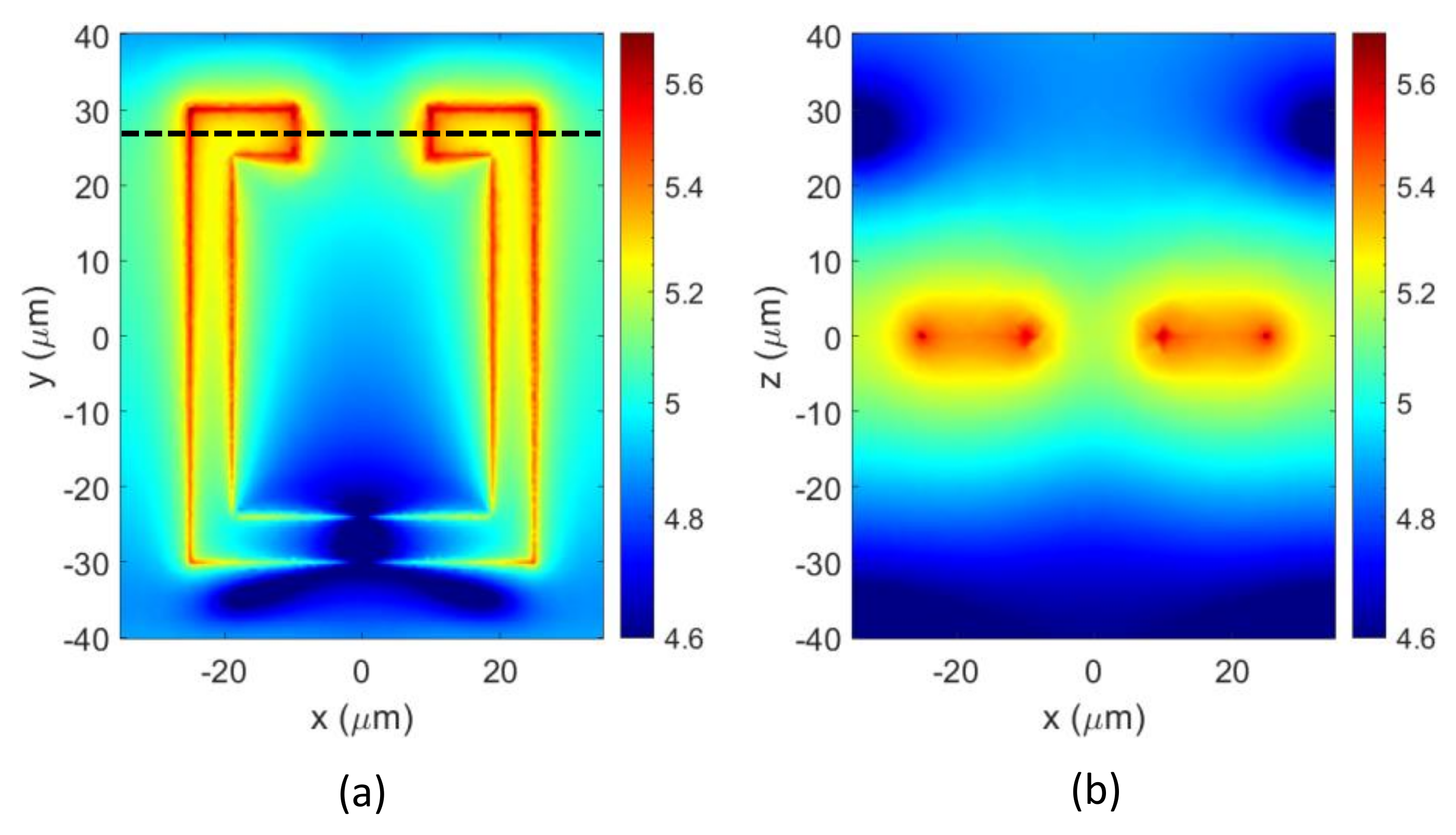
Figure 9a,b present the near-field distributions of the simulated PI-coated SRR deposited with an LC layer with a thickness of 310 µm in top and cross-section views, respectively. The near field is highly concentrated around the SRR, and the penetration depth of the field in the LC layer is small. Therefore, the extraordinary and ordinary refractive indices of the LC are determined by the wavelength and alignment effects.
The alignment in the middle of a thick metamaterial-imbedded cell is disordered as the anchoring energy of the alignment layers gradually decreases from their surfaces to the middle of the cell. The LC molecules in the middle of the cell are disordered. However, these molecules do not convect or flow, not only because the spectrum of the cell was measured in the chamber of the spectrometer at a constant temperature of 25 °C, but also because the assembly of the cell is reliable in our laboratory. Li et. al. depict that the MDA-98-1602 LC has an ordinary refractive index of 1.62 at 0.5 THz because 0.5 THz is in the absorption band with a peak that exceeds 2.5 THz [
20]. Therefore, the LC has a larger ordinary refractive index in the terahertz region than in the visible region.
This paragraph will study the effect of the thicknesses of LC cells on the long-range force of their alignment layers. A separate experiment for determining the long-range force of the alignment layers is carried out by measuring the transmittances of the LC cells. Each of the LC cells comprises two 188 μm thick PET substrates, which are separated by two plastic spacers. The thickness of the plastic spacers in each cell determines that of the LC layer of that cell. The LC layers in the cells have various thicknesses t of 310 µm, 710 µm, 1000 µm, and 1400 µm in the separate experiment. Polyimide films (AL-1426CA, Daily Polymer) are coated on both substrates of each cell as alignment layers, and are rubbed in a direction. A nematic LC (MDA-98-1602, Merck) is used in the cells. Each cell is placed between two parallel polarizers, and a probe beam from an He-Ne laser with a wavelength of 632.8 nm is normally incident to that cell. The polarized direction of the probe beam is set parallel to the rubbing direction of the polyimide layers of each cell. A power meter (Nova II, Ophir, Jerusalem, Israel) is placed behind the analyzer in order to measure the intensity of the transmitted light of each cell. The absolute transmittance of each cell in the separated experiment is obtained using a ratio of I/Iin, where I is the intensity of the transmitted light of that cell and Iin refers to the intensity of the light that is incident to the polarizer. The LC cells have absolute transmittances of 0.37, 0.22, 0.16, and 0.11 at LC thicknesses of 310 µm, 710 µm, 1000 µm, and 1400 µm, respectively. The transmittance of each cell is normalized using a ratio of I/I310, where I310 is the intensity of the transmitted light of the cell with an LC thickness of 310 µm.
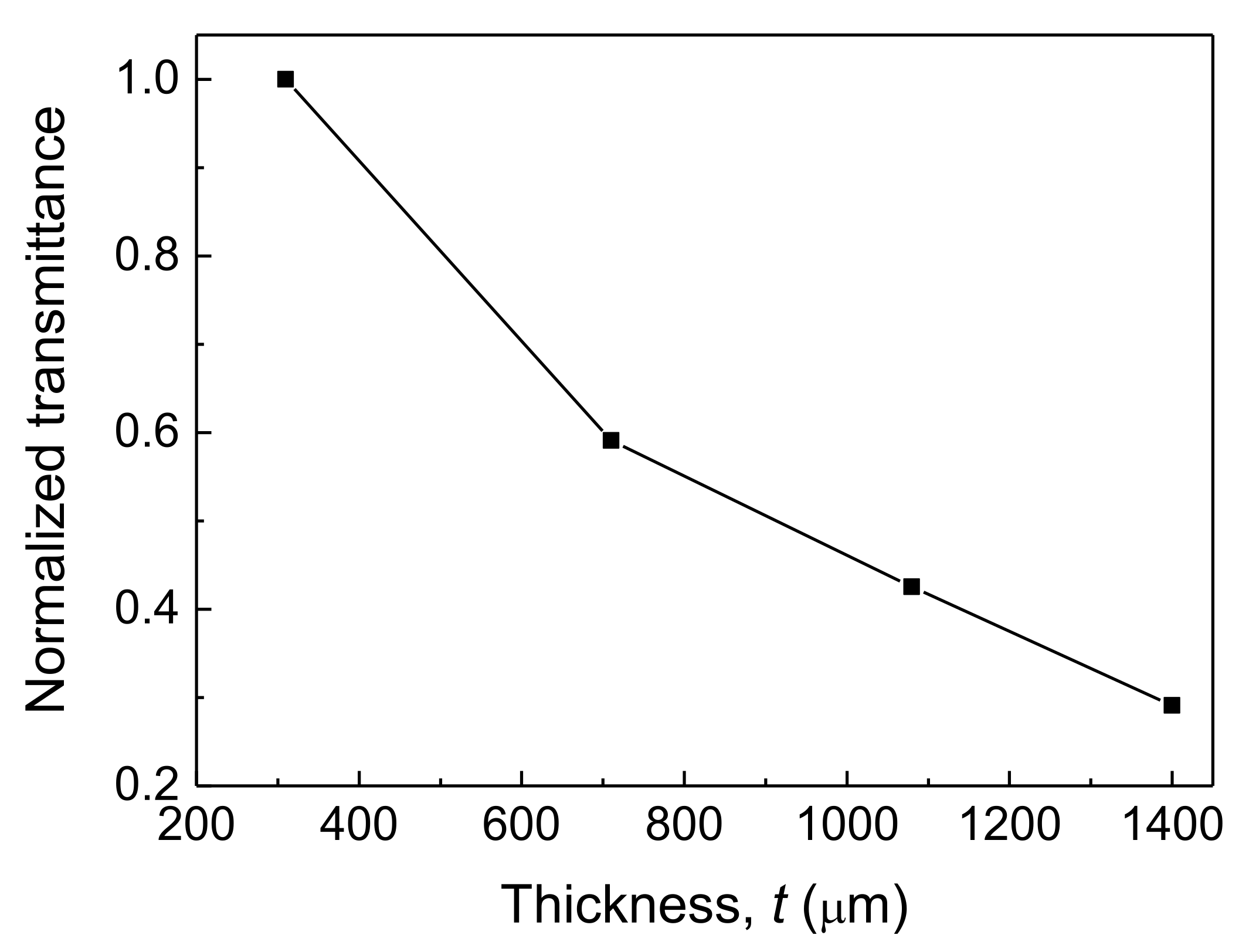
Figure 10 presents the transmittances of the LC cells at
t = 310 µm, 710 µm, 1000 µm, and 1400 µm in the separated experiment. The transmittances decrease as
t increases from 310 µm to 1400 µm. The decrease in the transmittances arises from the limited long-range force of the alignment layers in the LC cells. The alignment layers in an LC cell align the nematic domains of the LC layer up to distances from the surfaces of the layers above which they are not aligned. Therefore, the LC layer in the cell has the unaligned domain sandwiched between the two nematic domains. The nematic domains in the LC cells have the same thickness owing to the same long-range force of the alignment layers. In addition, the unaligned domain has a larger thickness in a thick LC layer than in a thin LC layer owing to the limited long-range force of the alignment layers. Therefore, the unaligned domains in the LC layers determine the alignment effect of the metamaterial-imbedded cells. The unaligned domain causes more schlieren textures in a thick LC layer than in a thin LC layer. The schlieren textures in each of the LC cells shed the probe beam and change its polarization. After this beam passes through the analyzer, its intensity is decreased. Therefore, the limited long-range force of the alignment layers in the LC cells decreases the normalized transmittances as
t increases from 310 µm to 1400 µm. The experimental results in
Figure 10 verify that the alignment layers in the metamaterial-imbedded LC cells have a limited long-range force in the LC layers.
A thickness factor is used to confirm the alignment effect of the LC cells. The thickness factor is define as a ratio of the thickness of the unaligned domain of each of the LC layers to that of the unaligned domain of the LC layer with an LC thickness of 310 µm. The thickness factors of the unaligned domains are inversely proportional to the normalized transmittances of the LC cells (
Figure 10). Therefore, the unaligned domains in the LC layers have thickness factors of 1.0, 1.69, 2.35, and 3.44 at
t = 310 µm, 710 µm, 1000 µm, and 1400 µm, respectively. This result reveals that the limited long-range force of the alignment layers in the LC cells increases the thicknesses of the unaligned domains as
t increases from 310 µm to 1400 µm, decreasing the normalized transmittances of the LC cells at the increase in
t.
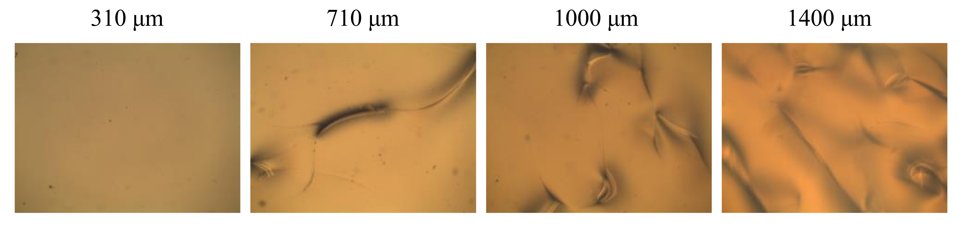
Figure 11 presents the polarizing optical microscopy pictures of the LC cells with LC thicknesses of 310 µm, 710 µm, 1000 µm, and 1400 µm under parallel polarizers. The aligned direction in each of the LC cells is parallel to the transmission axes of the polarizers. The schlieren textures in the LC cells increase as the LC thickness increases from 310 µm to 1400 µm. In addition, these textures shed the lights that are incident to the cells and change their polarization. Therefore, the normalized transmittances of the cells decrease at the increase in the LC thicknesses (
Figure 10).


 ,
, 


