Article

Effect of Annealing on the Characteristics of CoFeBY Thin Films

1
Department of Materials Science and Engineering, I-Shou University, Kaohsiung 840, Taiwan
2
Bachelor Program in Industrial Technology, National Yunlin University of Science and Technology, 123 University Road, Section 3, Douliou, Yunlin 64002, Taiwan
3
Graduate School of Materials Science, National Yunlin University of Science and Technology, 123 University Road, Section 3, Douliou, Yunlin 64002, Taiwan
4
Institute of Physics, Academia Sinica, Nankang, Taipei 11529, Taiwan
*
Author to whom correspondence should be addressed.
Coatings 2021, 11(2), 250; https://doi.org/10.3390/coatings11020250
Submission received: 20 January 2021 / Revised: 4 February 2021 / Accepted: 10 February 2021 / Published: 20 February 2021

Abstract

:
In this study, the addition of Y to CoFeB alloy can refine the grain size to study the magnetic, adhesion and optical properties of as-deposited and annealed CoFeB alloy. XRD analysis shows that CoFeB(110) has a BCC CoFeB (110) nanocrystalline structure with a thickness of 10–50 nm under four heat-treatment conditions, and a CoFeB(110) peak at 44° (2θ). The measurements of saturation magnetization (MS) and low frequency alternate-current magnetic susceptibility (χac) revealed a thickness effect owed to exchange coupling. The maximum MS of the 300 °C annealed CoFeBY film with a thickness of 50 nm was 925 emu/cm3 (9.25 × 10⁵ A/m). The maximum χac value of the 300 °C annealed CoFeBY nanofilms with a thickness of 50 nm was 0.165 at 50 Hz. After annealing at 300 °C, CoFeBY nanofilms exhibited the highest surface energy of 31.07 mJ/mm2, where the thickness of the nanofilms was 40 nm. Compared with the as-deposited CoFeBY nanofilms, due to the smaller average grain size after annealing, the transmittance of the annealed nanofilms increased. Importantly, when a CoFeB seed or buffer layer was replaced by a CoFeBY nanofilm, the thermal stability of the CoFeBY nanofilms was improved, promoting themselves on the practical MTJ applications.

1. Introduction

Since the discovery of Co50Fe50 in CoFe systems by Ellis in 1927 and Elmen in 1929, it has shown good soft magnetic properties [1]. These characteristics include high saturation magnetization (MS) and high Curie temperature (TC). Due to its excellent performance, Co–Fe system has attracted extensive attention. According to the above characteristics, Co-Fe alloys have the advantages of low coercivity (Hc) and good mechanical properties. However, with increasing annealing temperature, CoFe alloy has the disadvantage of serious degradation of magnetic anisotropy, which makes the effective use of these magnetic devices at high temperature difficult. Adding a third element to the CoFe matrix can help to overcome this problem [2,3,4,5,6,7]. Therefore, to find a kind of component that can improve the magnetothermal stability has become a primary research goal. For example, CoFeB thin films are widely used as free or pinned layers of spin valued magnetic tunnel junctions (MTJ) due to their high spin polarization and high tunneling magnetoresistance (TMR). They can be used in magnetoresistance random access memory (MRAM) and recording head devices [8,9,10,11,12,13]. Recently, more and more scholars have become interested in high-abundance rare earth magnetic materials. Due to the unique properties of rare earth elements, the high temperature resistance, mechanical strength, ductility and other physical properties of magnetic films can be improved. However, they can form compounds with transition metals such as iron, nickel and cobalt, some of which have Curie temperatures much higher than room temperature. Perhaps its properties can be used to improve the thermal stability of magnetic films at high temperature. Researchers who study magnetism and microstructure add yttrium (Y) to magnetic materials, or use Y to replace other elements in magnetic materials. Y addition plays the important role, including substitution or institute site in the material. When the radius of the Y atom is slightly larger, Y atoms can increase the degree of mismatch between atoms and promote the formation of amorphous phase. Y has a unique external electronic structure, which can remove impurities, prevent segregation and refine grains. Fe-Y composite oxides have a special place in temperature ferromagnetism [14]. In addition, the addition of a small amount of Y can significantly improve the corrosion resistance and chemical stability of the passive film [15,16]. A prior investigation was focused on the transition from amorphous state to nanocrystalline state and/or the improvement of nanocrystalline state to change the specific properties and magnetic properties of the films [17]. For example, substituting 2 at% Y for Nb can slow down the diffusion rate of alloying elements in fenbb alloy and reduce the growth of grains [18]. Compared with other rare earth elements such as Gd, TB or Dy, Y can obtain higher permeability [19]. When Y was doped into Finemet to investigate its effect on magnetic properties, Y was able to replace Nb to refine the grain [20]. In terms of hard magnetism, Fan et al. pointed out that the Y element can replace Ce in permanent magnet materials, which improves the thermal stability of magnetism and reduces the remanence coefficient and coercivity [21]. Zhang et al. stated that the addition of Y to NdFeB could significantly reduce the coercivity and effectively improve its heat resistance [22]. In the fields of soft magnetism, some scholars have successfully developed bulk-sized ternary Fe-X-B (X = Sc, Y, Dy, Ho, Er) amorphous alloys with the minor addition of rare earth elements. In addition, Fe-Y-B has high potential for industrial applications due to its low cost [23,24]. To date, several studies have shown that adding Y or increasing Y content can not only reduce the coercivity of the alloy, but also improve the thermal stability and reduce the production cost. However, there are few studies on the addition of rare earth elements in soft magnetic CoFe alloys. Based on the above literature, CoFeB thin films are commonly used in MTJ applications, but the processing temperature is high, so it is necessary to improve the thermal stability. To improve the magneto-thermal stability of CoFeB alloy, it is very important to study the effect of Y addition on the structure and magnetic properties of CoFeB alloy. The purpose of this study is to investigate the changes of the structure and magnetic properties of CoFeBY films with the thickness of the films, and to study the CoFeBY films after heat treatment, so as to determine whether they will change due to the high temperature environment, thus changing their magnetic efficiency. When the annealing temperature is 250 °C, the CoFeB layer is amorphous, but when the annealing temperature is increased to 300 °C, the amorphous phase becomes nanocrystalline, which leads to the TMR change of MTJ [25]. In this study, CoFeBY nanofilms were sputtered at room temperature (RT). Then the annealing temperature is set between 100 °C and 300 °C to determine whether the addition of Y can improve the thermal stability of the magnetic film at higher temperatures. However, few studies have been carried out on their magnetic-optical properties; therefore, this study discusses the transmittance of CoFeBY thin films. The main purpose of this study is to investigate the structure and magnetic properties of CoFeBY thin films with different thicknesses, and to discuss the structure, magnetic properties, adhesion and optical properties of CoFeBY films after heat treatment.

2. Materials and Methods

CoFeBY nanofilms with a thickness (tf) of 10–50 nm were sputtered on glass substrate at RT by direct current (DC) magnetron sputtering with 50 W power. After that, the progress followed by four conditions: (a) the as-deposited films were kept at RT, (b) annealed at a treatment temperature (TA) at 100 °C for 1 h, (c) annealed at 200 °C for 1 h, and (d) annealed at 300 °C for 1 h. The power density iwass 1.65 W/cm2 and the deposition rate was 1.2 nm/min. The base pressure of the chamber was 3 × 10⁻⁷ Torr, and the working pressure of Ar was 3 × 10⁻³ Torr. The pressure in the ex-situ annealed condition was 2.5 × 10⁻³ Torr with a specific Ar gas. The alloy target for the composition of CoFeBY was 40 at% Co, 40 at% Fe, 10 at% B and 10 at% Y. The surface morphology was detected by field emission scanning electron microscopy (SEM, Hitachi SU 8200, Tokyo, Japan). The grazing incidence X-ray Diffraction (GIXRD) patterns of CuKα1 (PAN analytical X’pert PRO MRD, Malvern Panalytical Ltd., Cambridge, UK) and low angle diffraction incidence of about two-degree angle were used to determine the structure of CoFeBY films. The in-plane low-frequency alternate-current magnetic susceptibility (χac) and hysteresis loops of Co40Fe40B10Y10 were studied by χac analyzer (XacQuan, MagQu Co. Ltd., New Tapei City, Taiwan) and alternating gradient magnetometer (AGM, PMC, OH, USA). Firstly, the standard sample was calibrated by external magnetic field χac analyzer. Then, the sample was inserted into the χac analyzer. The driving frequency is between 10 and 25,000 Hz. χac was determined by magnetization. All samples had the same shape and size to eliminate demagnetization. The χac valve is an arbitrary unit (a.u.), because the alternating current result corresponds to the reference standard sample, which is a comparative value. The relationship between magnetic susceptibility and frequency was measured by means of χac analyzer. The optimal resonance frequency (fres) was measured by the χac analyzer, which represents the frequency of the maximum χac. Before measurement, the contact angle should be properly air-cleaned on the surface. The contact angles of CoFeBY film were measured with deionized (DI) water and glycerol. The contact angles were measured when the samples take out from the chamber. The surface energy is obtained from the contact angles and some calculations [26,27,28]. The transmittance of CoFeBY was measured by spectral intelligent analyzer. The wavelength of visible light was from 500 nm to 800 nm.

3. Results

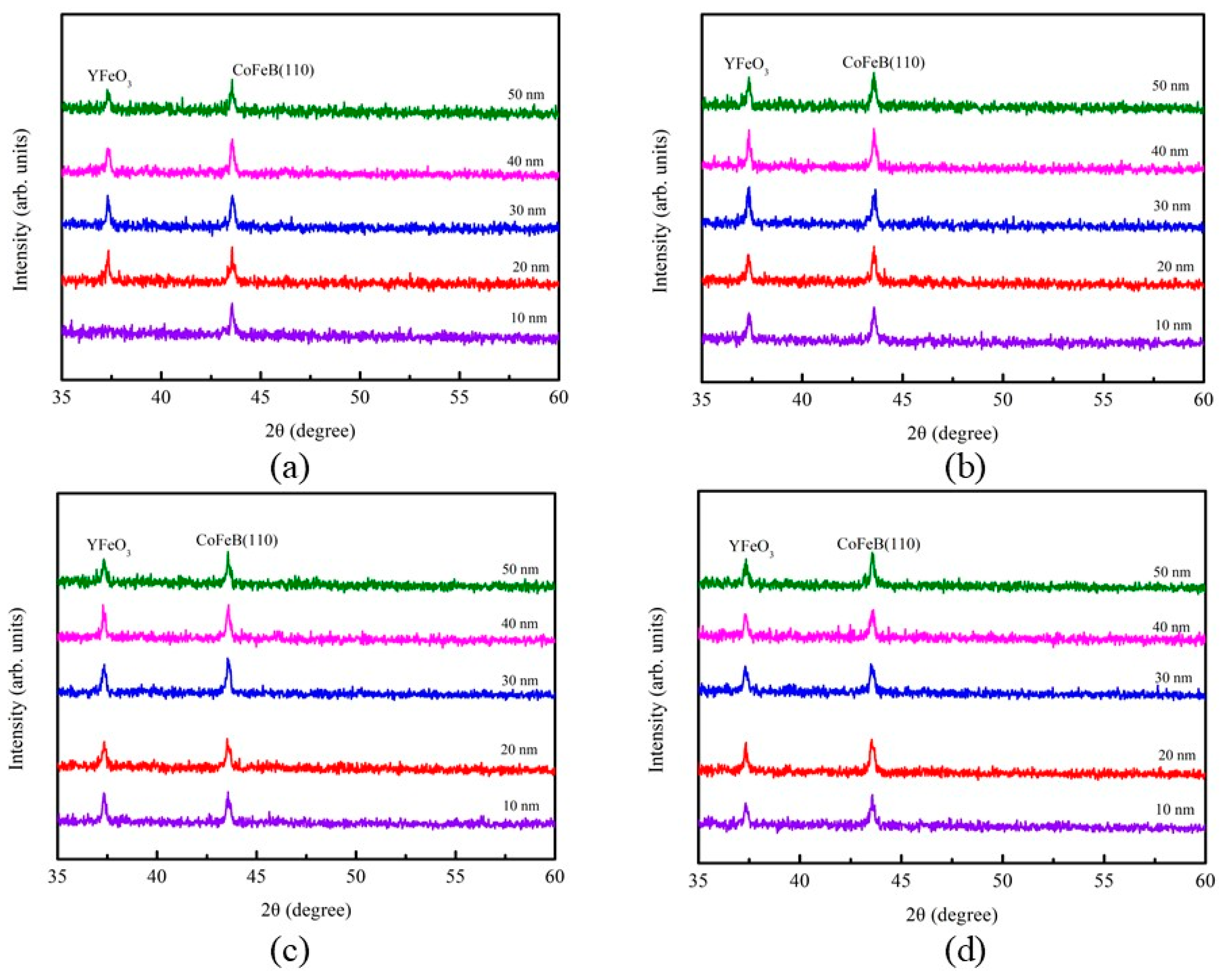
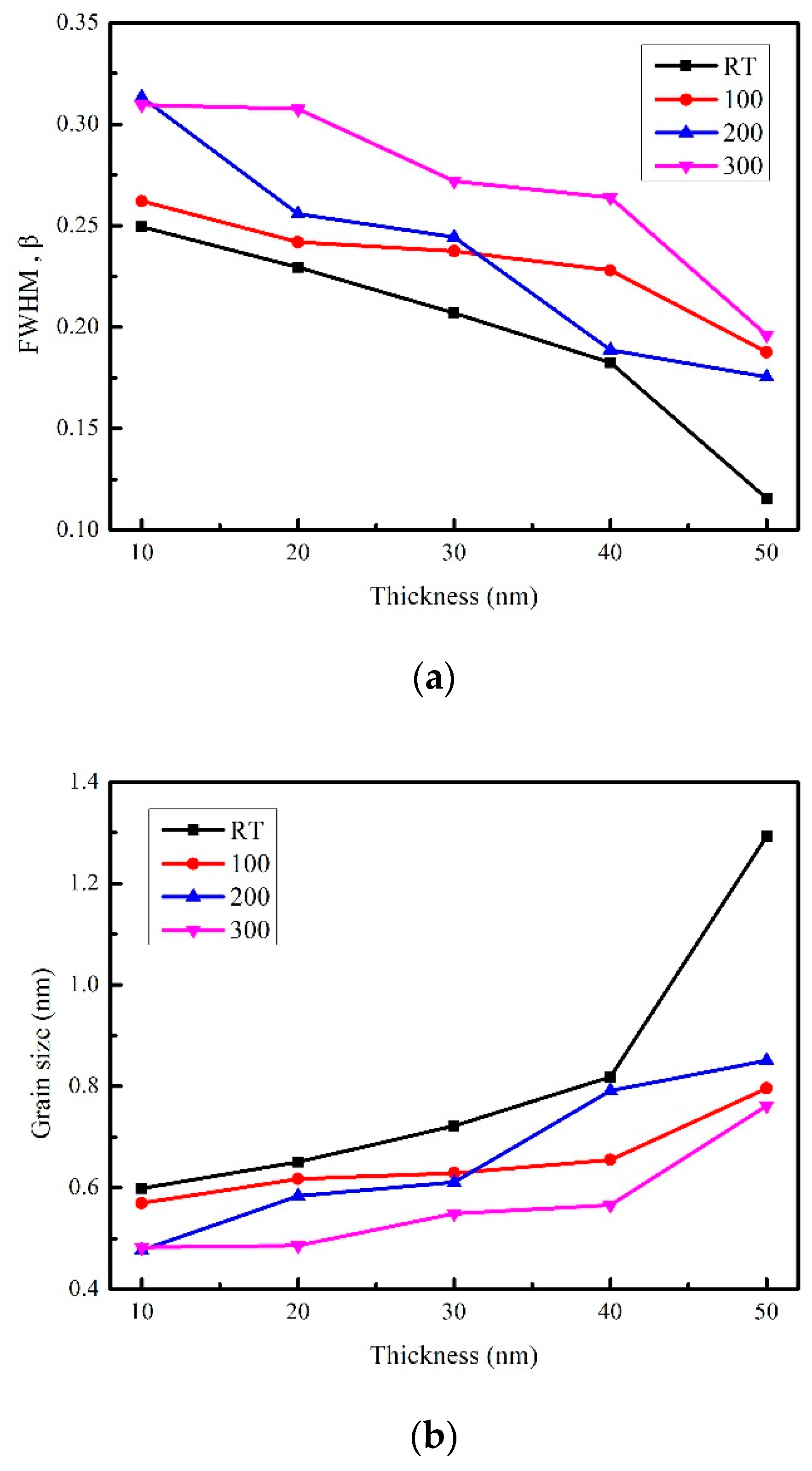
3.1. Structure Property

Figure 1 displays the XRD patterns of Co40Fe40B10Y10 nanofilms with a thickness of 10 to 50 nm on glass substrates under four conditions. Figure 1a shows the XRD patterns for the nanofilms at RT, while those of samples annealed at 100, 200 and 300 °C are shown in Figure 1b,c, respectively. The results of XRD are shown at different diffracted angles (2θ) between 35 and 60 degrees. The (110) body-centered cubic (BCC) structure for the CoFeB nanofilms was revealed to be around 2θ = 44°, indicating that the CoFeBY nanofilms belonged to a crystallized state [29]. Moreover, the YFeO3 oxide peaks found at 2θ = 37.3° may be attributed to the Y doping [30].
Figure 2a shows the full width at half maximum (FWHM, B) of the CoFeB (110) peak obtained in four conditions. The average crystallite sizes could be calculated according to the FWHM parameters obtained from the XRD patterns. Using the Scherrer formula (1), the average grain size of CoFeBY films under the studied conditions was calculated with CoFeB (110) peak.
Scherrer formula is [31]:
D = kλ/Bcosθ
where k (0.89) is the Scherrer’s constant, λ is the X-ray wavelength of Cu Kα1 line, B is the FWHM of the CoFeB (110) diffraction peaks, and θ is the half-angle of the diffraction peak. Figure 2b shows the average grain sizes, which were estimated from the half maximum (FWHM, B) of the CoFeB (110) peak under four conditions. The results demonstrated that the grain sizes of the films were related to the thickness, and the crystallinity of the films increased with the increase of thickness. The grain sizes of CoFeBY after annealing were smaller than those at RT, because the grain can be refined by adding an appropriate amount of Y [22].

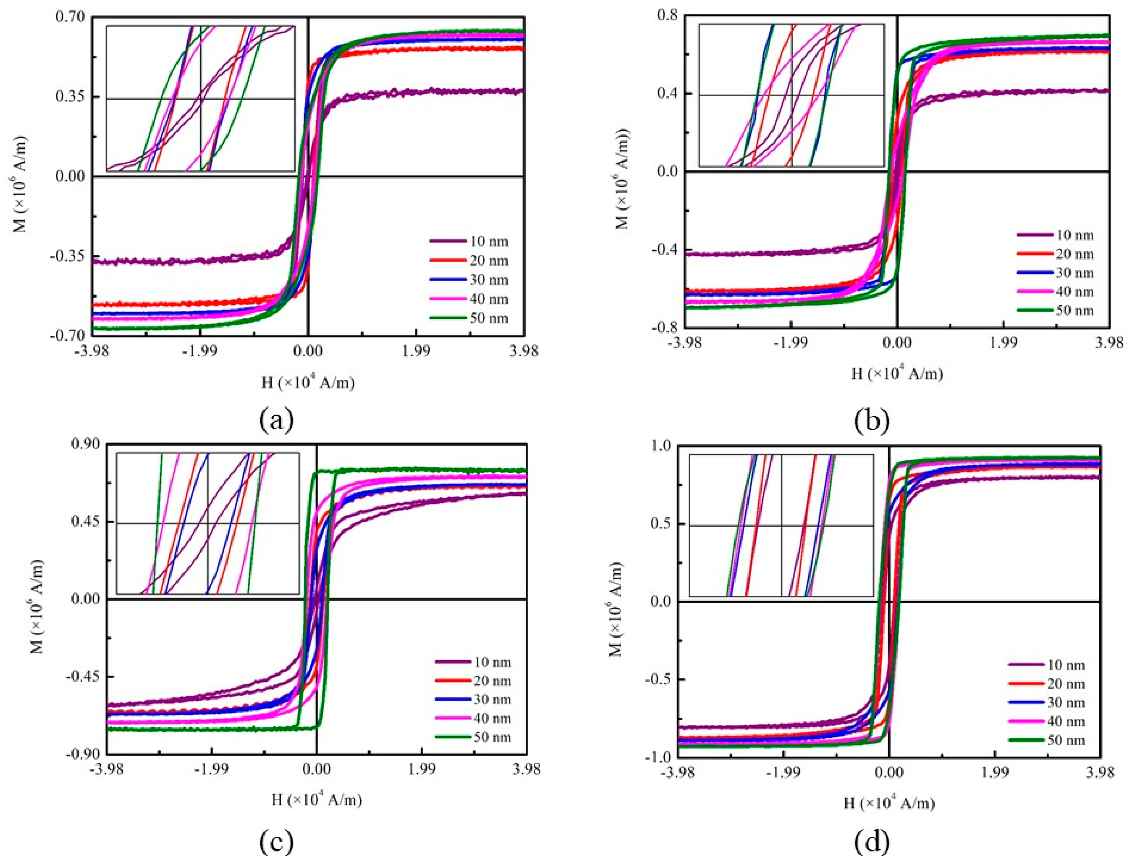
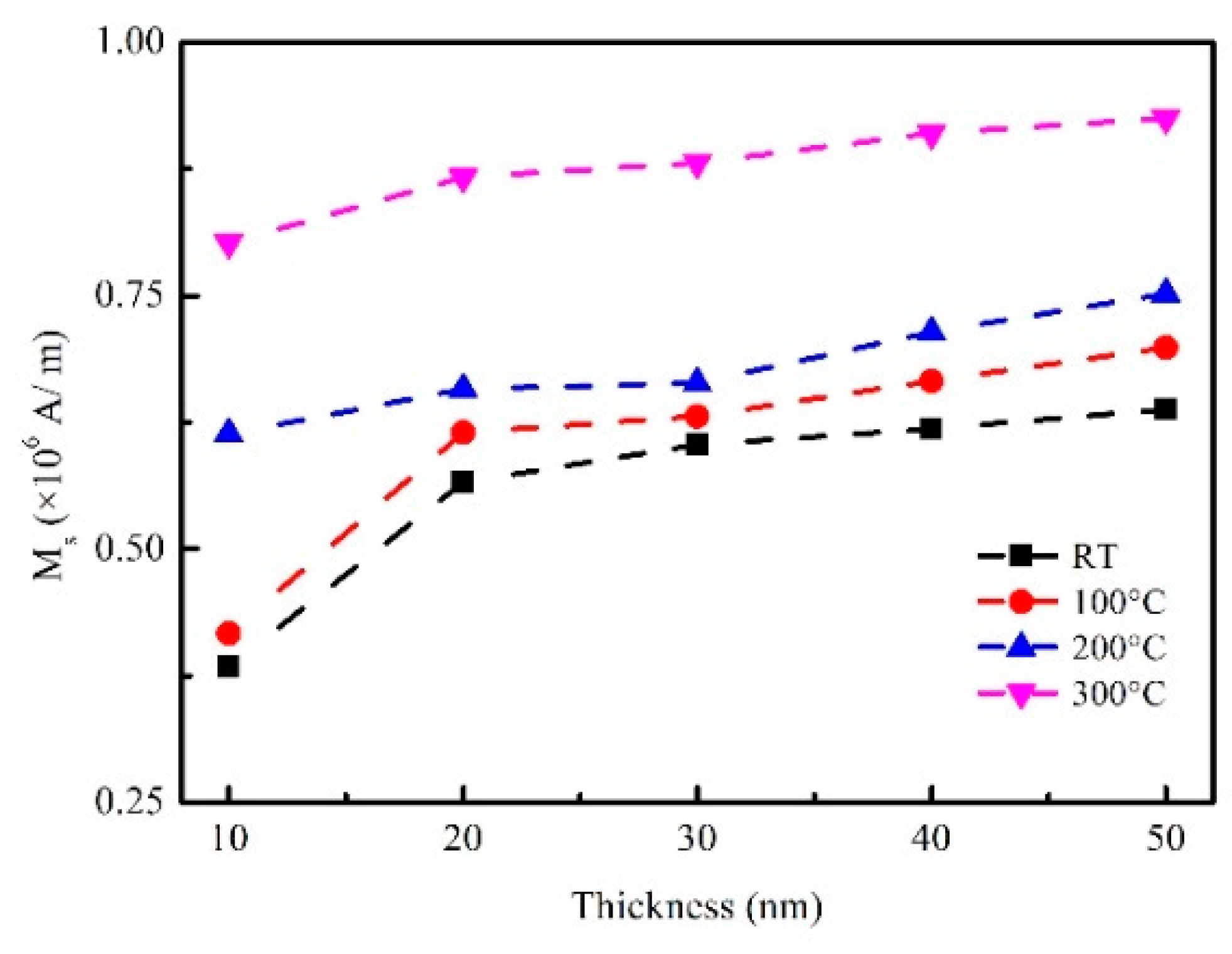
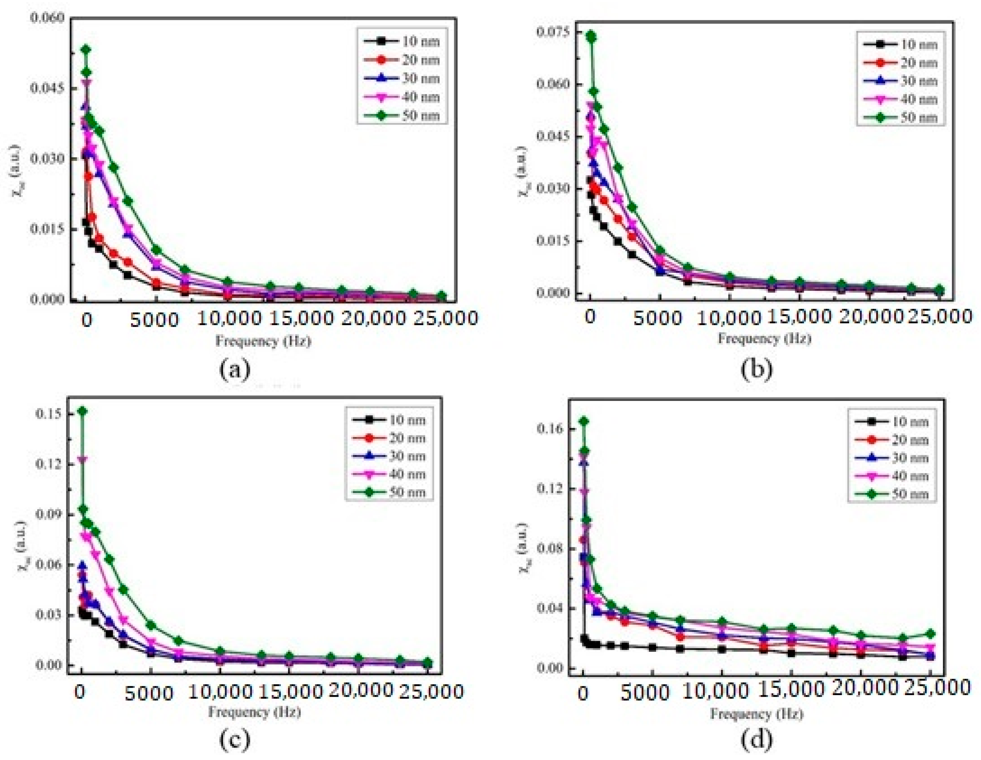
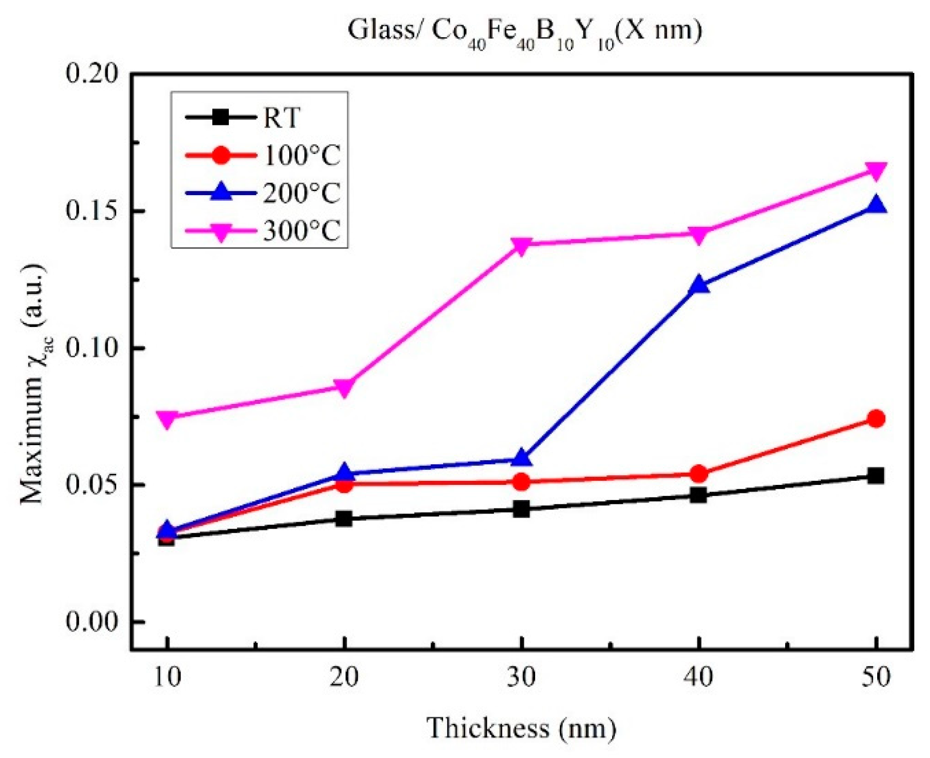
3.2. Magnetic Properties

Figure 3a–d plot the magnetic hysteresis loops of CoFeBY films under four conditions, in which the thicknesses were measured between 10 and 50 nm by AGM measurement, and the magnetic field is parallel to the film surface. The in-plane external field (Hext) field of 500 Oe (3.98 × 10⁴ A/m) was sufficient to observe the saturated magnetic spin status. The enlarged image illustrates low coercivity (HC), which suggests that the CoFeBY films were soft magnetic. These data are summarized in Table 1, which shows the magnetic properties of the nanofilms that were obtained by AGM. Figure 4 shows the corresponding saturation magnetization (MS) of the CoFeBY film under four conditions. The results revealed that the observed MS increased with the increase of thickness, indicating the thickness effect of MS on CoFeBY films. The MS value of CoFeBY films increased with the increase of annealing temperature. However, Ms was the highest after annealing at 300 °C, which was the best heat-resistant temperature in this study. The results show that the size of CoFeBY nanofilms is affected by the grain refinement, which improves the ferromagnetic spin exchange coupling and thus increases the Ms [32]. In addition, iron oxide was also detected in the XRD results, which may be the characteristic of antiferromagnetism, so the magnetization of iron oxide was deduced. In this study, the addition of Y and annealed treatment can increase the magnetization. Adding Y and heat treatment can increase the amount of magnetization.
The corresponding HC is displayed in Table 1. HC increased from 1.5 Oe to 15.1 Oe when tf ranged from 10 to 50 nm at room temperature; HC increased from 3.5 Oe to 18.8 Oe when tf ranged from 10 to 50 nm following annealing at 100 °C; HC increased from 4.5 Oe to 24.8 Oe when tf ranged from 10 to 50 nm following annealing at 200 °C; HC increased from 12.5 Oe to 23.1 Oe when tf ranged from 10 to 50 nm following annealing at 300 °C. In this study, the addition of Y led to the increase of HC, because the addition of Y refines the grain size, leading to an increase of HC. However, if the HC of CoFeBY films is between 10 and 20 Oe, and if they have high MS, the CoFeBY films will have soft magnetism, thus making them suitable for MRAM and recording head applications. The HC of nanofilm is usually enhanced by decreasing the grain size, which is an effect related to the transition from magnetic multi-domains to single domains [33,34].
Figure 5a–d show the results of CoFeBY films with thicknesses from 10 to 50 nm at four conditions (RT, 100, 200 and 300 °C) under which the low-frequency alternating-current magnetic susceptibility (χac) was studied. The low frequencies were in the range of 50 to 25,000 Hz. The results showed that the thickness of CoFeBY was between 10 and 50 nm, and the χac values of tf decreased with the increase of frequency (Hz). The maximum χac corresponding to various CoFeBY thicknesses under four conditions is shown in Figure 6. It could be found that the maximum χac value was 0.053 when tf was 50 nm at RT; the maximum χac value was 0.074 when tf was 50 nm at 100 °C; the maximum χac value was 0.152 when tf was 50 nm at 200 °C; and the maximum χac value was 0.165 when tf was 50 nm at 300 °C. Obviously, these results revealed the thickness effect of χac in CoFeBY films. With the increase of tf, the increase of χac was due to the thickness effect. The maximum χac value of annealed CoFeBY films was larger than that at RT. This is because CoFeBY films are affected by grain refinement, which improves the ferromagnetic spin exchange coupling and increases the χac value. Table 2 shows the optimal resonance frequency (ƒres) of CoFeBY. The maximum χac indicated that the spin sensitivity was the highest at the optimal resonant frequency. The peak of χac reflected the spin exchange-coupling interaction and dipole moment of the domain at frequency [35]. Additionally, the ƒres value of nanofilm is below 500 Hz, which allows CoFeBY nanofilm to be applied in soft magnetic devices. It was found that the ƒres values of all CoFeBY thicknesses were in the range from 50 to 500 Hz, indicating the maximum χac had the strongest spin sensitivity at this frequency [36].

3.3. Surface Morphology

To study the surface morphology and magnetic results, SEM images of CoFeBY at 40 nm were observed under four conditions, as shown in Figure 7. Figure 7a shows a looser surface morphology in the as-deposited state. The surface morphology after annealing at 100 °C is shown in Figure 7b, which shows the loose surface phenomenon. In Figure 7c, the surface morphology after annealing at 200 °C shows a dense distribution. The surface morphology of annealed at 300 °C was more densely distributed, as shown in Figure 7d. In addition, the surface morphology w very close to magnetism. In the cases of Figure 7c,d, some defects can be found, which lead to the enhancement of domain wall pinning effect. This can induce high coercivity and improve the spin coupling strength [37,38,39,40]. The susceptibility is also related to magnetic noise and exchange coupling. High susceptibility can enhance the strong dipole interaction effect [41].

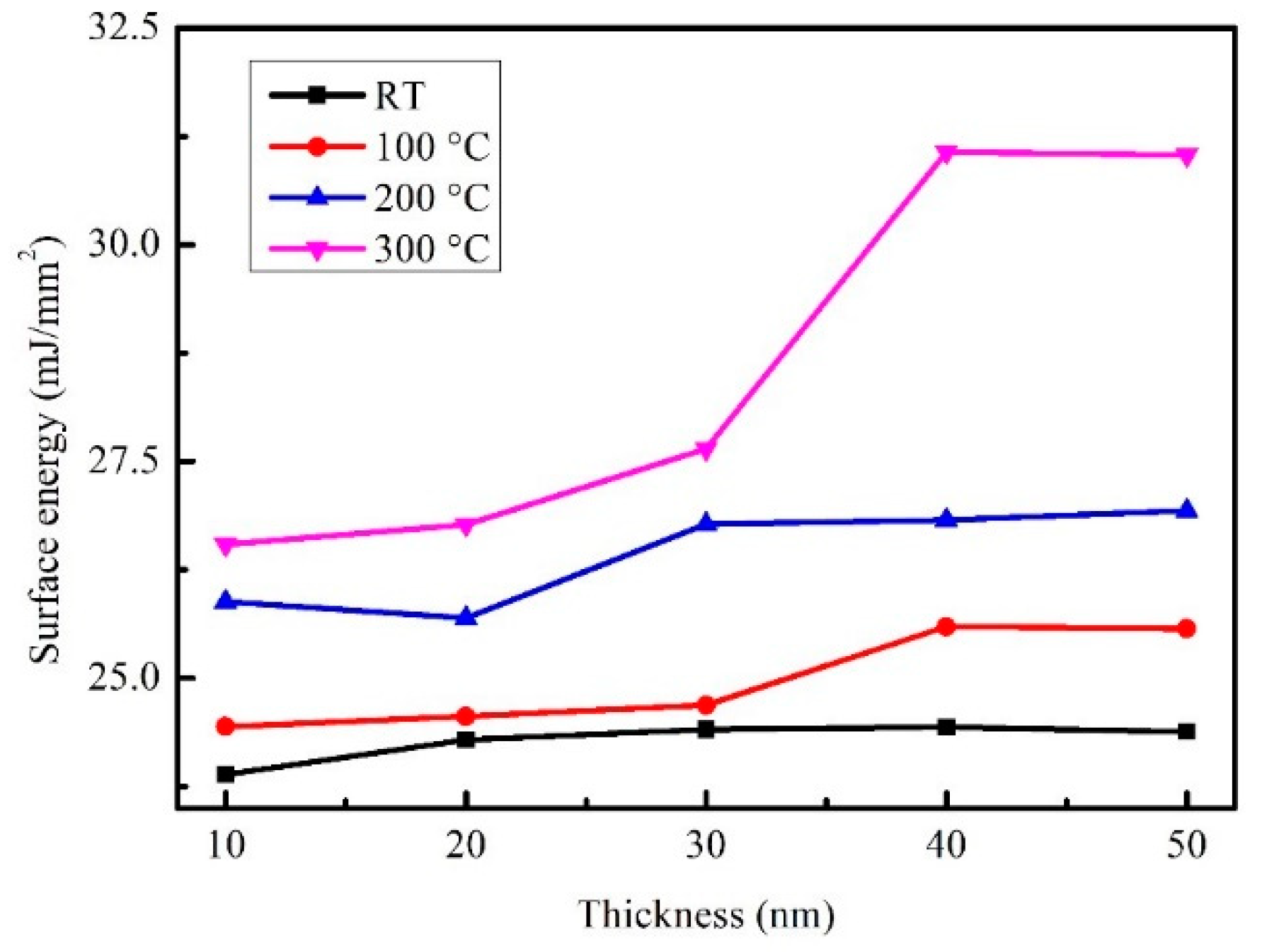
3.4. Analysis of Surface Energy and Adhesion

Table 3 displays the contact angle (θ) of the CoFeBY at RT. The contact angle of the films was investigated using DI water and glycerol. Table 3 shows the result of the contact angles (θ) of the CoFeBY using DI water, which were 81.7°, 81.1°, 80.9°, 81.3°, and 81.0°, as well as the contact angles (θ) with glycerol, which were 78.4°, 78.2°, 78.8°, 80.8°, and 79.5°, respectively.
Table 4 displays the contact angle (θ) of the Glass/CoFeBY at 100 °C. The contact angle of the films was investigated using DI water and glycerol. It shows the result of the contact angles (θ) of the CoFeBY using DI water, which were 79.4°, 79.3°, 79.4°, 81.0°, and 80.8°, as well as the contact angles (θ) with glycerol, which were 77.8°, 76.9°, 77.6°, 79.7°, and 80.0°, respectively.
Table 5 displays the contact angle (θ) of the CoFeBY at 200 °C. The contact angle of the films was investigated using DI water and glycerol. Table 5 shows the result of the contact angles (θ) of the CoFeBY using DI water, which were 77.6°, 78.3°, 78.0°, 79.5°, and 79.7°, as well as the contact angles (θ) with glycerol, which were 74.0°, 73.2°, 77.2°, 79.2°, and 79.5°, respectively.
Table 6 shows the annealed 300 °C result of the contact angles (θ) of the CoFeBY using DI water, which were 78.1°, 78.0°, 76.8°, 72.9°, and 71.7°, as well as the contact angles (θ) with glycerol, which were 75.9°, 77.0°, 75.8°, 72.7°, and 71.6°, respectively. From the above results, the contact angles of all CoFeBY films under RT, 100, 200 and 300 °C were less than 90°, indicating that the films were hydrophilic. When films are hydrophilic, they will have good wetting effect. In addition, the contact angle was closely related to the surface energy. When the surface free energy is high, the liquid absorption is large and the liquid absorption area is large, which leads to the decrease of the contact angle [42]. The surface energy was calculated according to the contact angle and Young’s equation [26,27,28].
Figure 8 shows the surface energy of the CoFeBY films. As a consequence, it indicates that the surface energy of as-deposited CoFeBY films was 24.4 mJ/mm2 at 40 nm, which was the highest value. When the annealing temperature was 100 and 200 °C, the best surface energy of 50 nm was 25.59 mJ/mm2 and 26.93 mJ/mm2, respectively. After annealing at 300 °C, the best surface energy was 31.07 mJ/mm2 at 40 nm, as shown in Figure 8. This result is consistent with SEM. When annealed at 300 °C for 40 nm, some defects can be observed, which are caused by high surface energy. After heat treatment, the surface energy of the film tended to become higher. With the increase of oxide content, the contact angle decreases. Low contact angle corresponded to higher surface energy. When the film has high surface energy, the adhesion is the strongest. These results show that it is easier to combine with free layer and pinning layer of layered magnetic tunnel junctions.

3.5. Analysis of Optical Properties

Figure 9 shows the optical transmittance spectra of CoFeBY at visible wavelengths of 500 to 800 nm. In Figure 9a (CoFeBY at RT), the transmittance (%) decreased from 37 to 10.5%, as tf changed from 10 to 50 nm. In Figure 9b (CoFeBY after annealing at 100 °C), the transmittance (%) decreased from 39.7 to 17%, when tf changed from 10 to 50 nm. In Figure 9c (CoFeBY after annealing at 200 °C), the transmittance (%) decreased from 40 to 16.7%, as tf changed from 10 to 50 nm. In Figure 9d (CoFeBY after annealing at 300 °C), the transmittance (%) decreased from 39.9 to 16%, when tf changed from 10 to 50 nm. The transmittance of annealed samples was higher than that of RT samples. The addition of Y and annealing could cause grain refinement [22]. With the increase of annealing temperature, only a slight change in the transmittance could be observed, because the crystal grain size did not change much, and the trend was not obvious. This result is in good agreement with the average grain size measured by XRD. The result indicated that thinner CoFeBY films have a higher transmission rate, because thicker films impeded the signal of the incident light and result in decreased transmittance. It is confirmed that the transmission of photons through the film is reduced due to the thickness effect and interface effect of the film [43,44].

4. Conclusions

Because of the addition of a suitable amount of Y in the alloys, the crystalline grain size was reduced after the post-annealing treatment. When the thickness of CoFeBY nanofilms increases from 10 to 50 nm, Ms tends to saturate, indicating the thickness effect of MS on CoFeBY nanofilm. The MS was improved when the temperature in the post-annealing process increased. The CoFeBY nanofilms were affected by size, and the refinement of grains facilitated the ferromagnetic spin exchange coupling, thus increasing the saturation magnetization. For the 300 °C annealed CoFeBY nanofilms, the maximum χac value was 0.165 at a 50 Hz fres, where the thickness of the films is 50 nm. The fres values of the CoFeBY nanofilms in all thickness conditions were less than 500 Hz, signifying that it could fulfill applications as the magnetic component in low-frequency sensors. The 50-nm-thick film following annealing at 300 °C had the highest surface energy in this work. It is worth mentioning that the strongest adhesion corresponded to the highest surface energy. At the same time, the samples undergoing annealing showed that the transmittance increased in comparison with the as-deposited films, because the average grain size became smaller after annealing, causing the transmittance to increase. The results show that the thermal stability of CoFeB nanofilms can be improved by adding appropriate amount of Y into CoFeB alloy, which indicates that the application of rare earth materials in soft magnetic materials needs further development.

Author Contributions

Conceptualization, W.-J.L., Y.-H.C. and Y.-T.C.; Methodology, Y.-T.C., Y.-C.C., D.-Y.T.; Validation, Formal analysis, Y.-T.C. and P.-W.C.; Investigation, Y.-T.C. and W.-J.L.; Resources, T.-H.W.; Writing—original draft preparation, Y.-T.C.; Writing—review and editing, Y.-T.C. and W.-J.L.; Supervision, Y.-T.C. and Y.-H.C.; Project administration, Y.-T.C. and T.-H.W.; Funding acquisition, W.-J.L. and Y.-H.C. All authors have read and agreed to the published version of the manuscript.

Funding

This work was supported by the Ministry of Science and Technology, under Grant No. MOST108-2221-E-224-015-MY3, MOST105-2112-M-224-001, and National Yunlin University of Science and Technology, under Grant No. 110T06.

Data Availability Statement

No new data were created or analyzed in this study. Data sharing is not applicable to this article.

Conflicts of Interest

The authors declare that there is no conflict of interests regarding the publication of this paper. The funders had no role in the design of the study; in the collection, analyses, or interpretation of data; in the writing of the manuscript, or in the decision to publish the results.

References

  1. Elmen, G.W. Magnetic alloys of iron, nickel, and cobalt. J. Frankl. Inst. 1929, 207, 583–617. [Google Scholar] [CrossRef]
  2. Ogasawara, T.; Oogane, M.; Mahdawi, M.A.; Tsunoda, M.; Ando, Y. Effect of second-order magnetic anisotropy on non-linearity of conductance in CoFeB/MgO/CoFeB magnetic tunnel junction for magnetic sensor devices. Sci. Rep. 2019, 9, 1–9. [Google Scholar] [CrossRef]
  3. Devolder, T.; Couet, S.; Swerts, J.; Mertens, S.; Rao, S.; Kar, G.S. Effect of Tantalum Spacer Thickness and Deposition Con-ditions on the Properties of MgO/CoFeB/Ta/CoFeB/MgO Free Layers. IEEE Mag. Lett. 2019, 10, 1–4. [Google Scholar] [CrossRef] [Green Version]
  4. Honjo, H.; Ikeda, S.; Sato, H.; Nishioka, K.; Watanabe, T.; Miura, S.; Nasuno, T.; Noguchi, Y.; Yasuhira, M.; Tanigawa, T.; et al. Impact of Tungsten Sputtering Condition on Magnetic and Transport Properties of Double-MgO Magnetic Tunneling Junction With CoFeB/W/CoFeB Free Layer. IEEE Trans. Mag. 2017, 53, 1–4. [Google Scholar] [CrossRef]
  5. Manos, O.; Bougiatioti, P.; Dyck, D.; Huebner, T.; Rott, K.; Schmalhorst, J.M.; Reiss, G. Correlation of tunnel magnetore-sistance with the magnetic properties in perpendicular CoFeB-based junctions with exchange bias. J. Appl. Phys. 2019, 125, 1–6. [Google Scholar] [CrossRef] [Green Version]
  6. Lv, H.; Fidalgo, J.; Silva, A.V.; Leitao, D.C.; Kampfe, T.; Riedel, S.; Langer, J.; Wrona, J.; Ocker, B.; Freitas, P.P.; et al. Assessment of conduction mechanisms through MgO ultrathin barriers in CoFeB/MgO/CoFeB perpendicular magnetic tunnel junctions. Appl. Phys. Lett. 2019, 114, 102402. [Google Scholar] [CrossRef]
  7. Iwata-Harms, J.M.; Jan, G.; Serrano-Guisan, S.; Thomas, L.; Liu, H.; Zhu, J.; Lee, Y.-J.; Le, S.; Tong, R.-Y.; Patel, S.; et al. Ultrathin perpendicular magnetic anisotropy CoFeB free layers for highly efficient, high speed writing in spin-transfer-torque magnetic random access memory. Sci. Rep. 2019, 9, 1–7. [Google Scholar] [CrossRef] [PubMed] [Green Version]
  8. Ramazanov, M.A.; Maharramov, A.M.; Sultanova, C.R. Magnetoresistance effect in PP + Fe based nanocomposite system. Integr. Ferroelectr. 2018, 192, 141–145. [Google Scholar] [CrossRef]
  9. Albisetti, E.; Scaramuzzi, G.; Rinaldi, C.; Cantoni, M.; Bertacco, R.; Petti, D. Temperature dependence of the magnetic properties of IrMn/CoFeB/Ru/CoFeB exchange biased synthetic antiferromagnets. Materials 2020, 13, 387. [Google Scholar] [CrossRef] [Green Version]
  10. Sun, J.Z.; Trouilloud, P.L.; Lauer, G.P.; Hashemi, P. , Bias dependent conductance in CoFeB-MgO-CoFeB magnetic tunnel junctions as an indicator for electrode magnetic condition at barrier interfaces. AIP Adv. 2019, 9, 1–6. [Google Scholar] [CrossRef] [Green Version]
  11. Ota1, S.; Ono, M.; Matsumoto, H.; Ando, A.; Sekitani, T.; Kohno, R.; Iguchi, S.; Koyama, T.; Chiba, D. CoFeB/MgO-based magnetic tunnel junction directly formed on a flexible substrate. Appl. Phys. Express 2019, 12, 1–4. [Google Scholar] [CrossRef]
  12. Lee, D.-Y.; Hong, S.-H.; Lee, S.-E.; Park, J.-G. Dependency of Tunneling-Magnetoresistance Ratio on Nanoscale Spacer Thickness and Material for Double MgO Based Perpendicular-Magnetic-Tunneling-Junction. Sci. Rep. 2016, 6, 38125. [Google Scholar] [CrossRef] [Green Version]
  13. Rylkov, V.V.; Nikolaev, S.N.; Demin, V.A.; Emelyanov, A.V.; Sitnikov, A.V.; Nikiruy, K.E.; Levanov, V.A.; Presnyakov, M.Y.; Taldenkov, A.N.; Vasiliev, A.L.; et al. Transport, magnetic, and memristive properties of a nanogranular (CoFeB)x (LiNbOy)100−x composite material. J. Exp. Theor. Phys. 2018, 126, 353–367. [Google Scholar] [CrossRef]
  14. Sui, Y.; Liu, X.; Liu, C. Room temperature ferromagnetic property of Fe-Y (Fe: Y-6.5) composite oxide nano-cluster via an extremely easy and scalable method. J. Rare Earths 2020. [Google Scholar] [CrossRef]
  15. Zhang, T.; Li, D. Effect of alloying yttrium on corrosion–erosion behavior of 27Cr cast white iron in different corrosive slurries. Mater. Sci. Eng. A 2002, 325, 87–97. [Google Scholar] [CrossRef]
  16. Luo, T.; Yang, Y.; Li, Y.; Dong, X. Influence of rare earth Y on the corrosion behavior of as-cast AZ91 alloy. Electrochim. Acta 2009, 54, 6433–6437. [Google Scholar] [CrossRef]
  17. KSaksl; Bednarcčík, J.; Nicula, R.; Burkel, E.; Roth, S.; Franz, H. The influence of short-time ball-milling on the stability of amorphous CoFeB alloys. J. Phys. Condens. Matter 2007, 19, 1–14. [Google Scholar]
  18. Chrobak, A.; Nosenko, V.; Haneczok, G.; Boichyssyn, L.; Karolus, M.; Kotur, B. Influence of rare earth elements on crystal-lization of Fe82Nb2B14RE2 (RE = Y, Gd, Tb, and Dy) amorphous alloys. J. Non Cryst. Solids. 2011, 357, 4–9. [Google Scholar] [CrossRef]
  19. Chrobak, A.; Nosenko, V.K.; Haneczok, G.; Boichyshyn, L.; Kotur, B.; Bajorek, A.; Životský, O.; Hendrych, A. Effect of rare earth additions on magnetic properties of Fe82Nb2B14RE2 (RE = Y, Gd, Tb and Dy) amorphous alloys. Mater. Chem. Phys. 2011, 130, 603–608. [Google Scholar] [CrossRef]
  20. Mao, Y.; Zhu, Z.; Zhao, H. Microstructures and soft magnetic properties of Fe73.5Cu1Nb3−xSi13.5B9Yx (x = 0–1.5) alloys. J. Rare Earths 2020. [Google Scholar] [CrossRef]
  21. Fan, X.; Chen, K.; Guo, S.; Chen, R.; Lee, D.; Yan, A.; You, C. Core-shell Y-substituted Nd-Ce-Fe-B sintered magnets with enhanced coercivity and good thermal stability. Appl. Phys. Lett. 2017, 110, 1–4. [Google Scholar] [CrossRef]
  22. Zhang, C.H.; Luo, Y.; Yu, D.B.; Quan, N.T.; Wu, G.Y.; Dou, Y.K.; Hu, Z.; Wang, Z.L. , Permanent magnetic properties of Nd–Fe–B melt-spun ribbons with Y substitution. Rare Metals 2020, 39, 55–61. [Google Scholar] [CrossRef]
  23. Huang, X.M.; Wang, X.D.; Jiang, J.Z. Origin of high glass forming ability of Y- containing FeB-based alloys. J. Alloys Compd. 2009, 485, L35–L38. [Google Scholar] [CrossRef]
  24. Liu, S.; Cao, Q.; Wang, X.; Zhang, D.; Su, Q.; Du, G.; Jiang, J. Effects of thickness on structure and magnetic property of Fe-Y-B thin films. Thin Solid Films 2016, 616, 608–617. [Google Scholar] [CrossRef]
  25. Jimbo, M.; Komiyama, K.; Shirota, Y.; Fujiwara, Y.; Tsunashima, S.; Matsuura, M. Thermal stability of spin valves using amorphous CoFeB. J. Magn. Magn. Mater. 1997, 165, 308–311. [Google Scholar] [CrossRef]
  26. Ma, K.; Chung, T.S.; Good, R.J. Surface energy of thermotropic liquid crystalline polyesters and polyesteramide. J. Polym. Sci. 1998, 36, 2327–2337. [Google Scholar] [CrossRef]
  27. Owens, D.K.; Wendt, R.C. Estimation of the surface free energy of polymers. J. Appl. Polym. Sci. 1969, 13, 1741–1747. [Google Scholar] [CrossRef]
  28. Kaelble, D.H.; Uy, K.C. A Reinterpretation of Organic Liquid-Polytetrafluoroethylene Surface Interactions. J. Adhes. 1970, 2, 50–60. [Google Scholar] [CrossRef]
  29. Chen, Y.-T.; Chang, C. Effect of grain size on magnetic and nanomechanical properties of Co60Fe20B20 thin films. J. Alloy. Compd. 2010, 498, 113–117. [Google Scholar] [CrossRef]
  30. Liu, T.; Shen, H.; Wang, C.; Chou, W. Structure evolutionofY2O3 nanoparticle/Fe composite during mechanicalmillin-gandannealing. Prog. Nat. Sci. 2019, 23, 434–439. [Google Scholar] [CrossRef] [Green Version]
  31. Cullity, B.D.; Weymouth, J.W. Elements of X-Ray Diffraction. Am. J. Phys. 1957, 25, 394–395. [Google Scholar] [CrossRef] [Green Version]
  32. Jen, S.U.; Yao, Y.D.; Chen, Y.T.; Wu, J.M.; Lee, C.C.; Tsai, T.L.; Chang, Y.C. Magnetic and electrical properties of amorphous CoFeB films. J. Appl. Phys. 2006, 99, 053701. [Google Scholar] [CrossRef] [Green Version]
  33. Noce, R.D.; Benedetti, A.V.; Magnani, M.; Passamani, E.C.; Kumar, H.; Cornejo, D.R.; Ospina, C.A. , Structural, morpho-logical and magnetic characterization of electrodeposited Co–Fe–W alloys. J. Alloys Compd. 2014, 611, 243–248. [Google Scholar] [CrossRef]
  34. R. C. O’Handley. Modern Magnetic Materials; J. Wiley & Sons Inc.: New York, NY, USA, 2000. [Google Scholar]
  35. Yang, S.; Chieh, J.; Wang, W.; Yu, C.; Hing, N.; Horng, H.; Hong, C.-Y.; Yang, H.; Chang, C.; Lin, H. Magnetic nanoparticles for high-sensitivity detection on nucleic acids via superconducting-quantum-interference-device-based immunomagnetic reduction assay. J. Magn. Magn. Mater. 2011, 323, 681–685. [Google Scholar] [CrossRef]
  36. Chen, Y.T.; Xie, S.M.; Jheng, H.Y. The low-frequency alternative-current magnetic susceptibility and electrical properties of Si(100)/Fe40Pd40B20(X Å)/ZnO(500 Å) and Si(100)/ZnO(500 Å)/Fe40Pd40B20(Y Å) systems. J. Appl. Phys. 2013, 113, 1–3. [Google Scholar] [CrossRef] [Green Version]
  37. Zhang, J.; Li, Y.-X.; Wang, F.; Shen, B.-G.; Sun, J.-R. Coercivity mechanism of nanocomposite Sm-Co/Fe multilayer films. J. Appl. Phys. 2010, 107, 43911. [Google Scholar] [CrossRef] [Green Version]
  38. Bendavid, A.; Martin, P.; Wieczorek, L. Morphology and optical properties of gold thin films prepared by filtered arc deposition. Thin Solid Films 1999, 354, 169–175. [Google Scholar] [CrossRef]
  39. Xu, S.T.; Ma, Y.Q.; Zheng, G.H.; Dai, Z.X. Simultaneous effects of surface spins: Rarely large coercivity, high remanence magnetization and jumps in the hysteresis loops observed in CoFe2O4 nanoparticles. Nanoscale 2015, 7, 6520–6526. [Google Scholar] [CrossRef]
  40. Muroi, M.; Street, R.; McCormick, P.G.; Amighian, J. Magnetic properties of ultrafine MnFe2O4 powders prepared by mechanochemical processing. Phys. Rev. B 2001, 63, 1–7. [Google Scholar] [CrossRef]
  41. Jonsson, T.; Nordblad, P.; Svedlindh, P. Dynamic study of dipole-dipole interaction effects in a magnetic nanoparticle system. Phys. Rev. B 1997, 57, 497–504. [Google Scholar] [CrossRef]
  42. Kong, S.H.; Okamoto, T.; Nakagawa, S. [Ni-Fe/Si] double seedlayer with low surface energy for Fe-Co-B soft magnetic underlayer with high Hk for perpendicular magnetic recording media. IEEE Trans. Magn. 2004, 40, 2389–2391. [Google Scholar] [CrossRef]
  43. Tavakoli, M.M.; Dastjerdi, H.T.; Zhao, J.; Shulenberger, K.E.; Carbonera, C.; Po, R.; Cominetti, A.; Bianchi, G.; Klein, N.D.; Bawendi, M.G.; et al. Light Management in Organic Photovoltaics Processed in Ambient Conditions Using ZnO Nanowire and Antireflection Layer with Nanocone Array. Small 2019, 15, e1900508. [Google Scholar] [CrossRef] [PubMed]
  44. Erdem, T.; Yang, L.; Xu, P.; Altıntas, Y.; O’Neil, T.; Caciagli, A.; Ducati, C.; Mutlugun, E.; Scherman, O.A.; Eiser, E.; et al. Transparent Films Made of Highly Scattering Particles. Langmuir 2020, 36, 911–918. [Google Scholar] [CrossRef] [PubMed]
Figure 1. XRD patterns of CoFeBY films. (a) RT, (b) after annealing at 100 °C, (c) after annealing at 200 °C, (d) after annealing at 300 °C.
Coatings 11 00250 g001
Figure 2. (a) The full width at half maximum (FWHM, B) of CoFeBY films, (b) the average grain size of CoFeBY films.
Coatings 11 00250 g002
Figure 3. In-plane magnetic hysteresis loop of CoFeBY nanofilms: (a) RT, (b) after annealing at 100 °C, (c) after annealing at 200 °C, (d) after annealing at 300 °C.
Coatings 11 00250 g003
Figure 4. Saturation magnetization (MS) of CoFeBY nanofilms.
Coatings 11 00250 g004
Figure 5. The low-frequency alternate-current magnetic susceptibility (χac) as a function of the frequency from 10 to 25,000 Hz. (a) RT, (b) after annealing at 100 °C, (c) after annealing at 200 °C, (d) after annealing at 300 °C.
Coatings 11 00250 g005
Figure 6. Maximum alternate-current magnetic susceptibility for the CoFeBY films.
Coatings 11 00250 g006
Figure 7. SEM micrographs of CoFe40BY 40 nm. (a) RT, (b) after annealing at 100 °C, (c) after annealing at 200 °C, (d) after annealing at 300 °C.
Coatings 11 00250 g007
Figure 8. Surface energy of CoFeBY nanofilms.
Coatings 11 00250 g008
Figure 9. Transmittance of CoFeBY films. (a) RT, (b) after annealing at 100 °C, (c) after annealing at 200 °C, (d) after annealing at 300 °C.
Coatings 11 00250 g009
Table 1. Coercivity (Hc) of CoFeBY nanofilms.
Thickness
(nm)
RT
(Oe)
After Annealing at 100 °C (Oe)After Annealing at 200 °C (Oe)After Annealing at 300 °C (Oe)
101.53.54.512.5
2012.312.015.813.4
3012.018.012.920.3
4015.115.124.121.9
5012.518.824.823.1
Table 2. Optimal resonance frequency for films of various thicknesses.
Thickness
(nm)
RT
(Hz)
After Annealing at 100 °C (Hz)After Annealing at 200 °C (Hz)After Annealing at 300 °C (Hz)
1050505050
2050505050
3050505050
405010010050
5050505050
Table 3. Average contact angles of CoFeBY nanofilms at RT with DI water and glycerol.
Co40Fe40B10Y10 (10–50 nm)Contact Angle (θ) with DI Water as Test LiquidContact Angle (θ) with Glycerol as Test Liquid
10 nm81.7°78.4°
20 nm81.1°78.2°
30 nm80.9°78.8°
40 nm81.3°80.8°
50 nm81.0°79.5°
Table 4. Average contact angles of CoFeBY nanofilms after annealing at 100 °C with DI water and glycerol.
Co40Fe40B10Y10 (10–50 nm)Contact Angle (θ) with DI Water as Test LiquidContact Angle (θ) with Glycerol as Test Liquid
10 nm79.4°77.8°
20 nm79.3°76.9°
30 nm79.4°77.6°
40 nm81.0°79.7°
50 nm80.8°80.0°
Table 5. Average contact angles of CoFeBY nanofilms after annealing at 200 °C with DI water and glycerol.
Co40Fe40B10Y10 (10–50 nm)Contact Angle (θ) with DI Water as Test LiquidContact Angle (θ) with Glycerol as Test Liquid
10 nm77.6°74.0°
20 nm78.3°73.2°
30 nm78.0°77.2°
40 nm79.5°79.2°
50 nm79.7°79.5°
Table 6. Average contact angles of CoFeBY nanofilms after annealing at 300 °C with DI water and glycerol.
Co40Fe40B10Y10 (10–50 nm)Contact Angle (θ) with DI Water as Test LiquidContact Angle (θ) with Glycerol as Test Liquid
10 nm78.1°75.9°
20 nm78.0°77.0°
30 nm76.8°75.8°
40 nm72.9°72.7°
50 nm71.7°71.6°
Publisher’s Note: MDPI stays neutral with regard to jurisdictional claims in published maps and institutional affiliations.

